
Chapter 19 — Wings Build Prep
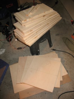
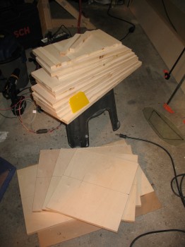
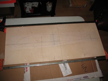
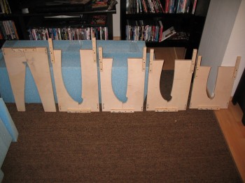
12 July 2012 — I spent about 2-1/2 hours at the wood shop on Ramstein today. Not nearly as bad as last time…I cut out all the wing jig segments from 3/4″ plywood (the plans call for 1/2″ plywood but their’s was REALLY warped, so I went with nearly the only plywood left in Germany: 3/4″). I then cut 17 each 1″ x 8″ connector pieces that will eventually get mounted to each segment of the jig. In building the jigs, I’m making every attempt to get the wing jig outline to match exactly per the outline of the paper template. To do this, I’ve taken into account the blade kerf width on each saw I use.
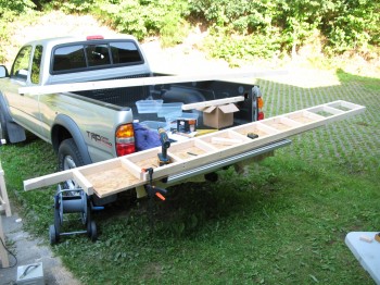
Back at the shop, I glued all the forward pieces of the jigs together and clamped them.
•••
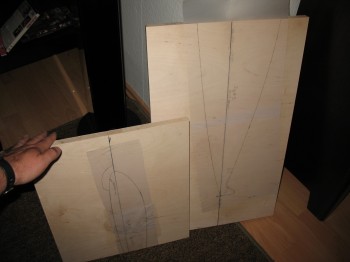
14 July 2012 — Today I glued the paper wing jig templates to the cut 3/4″ plywood wing jigs. It took a while to find the trailing edge tip for one of the templates, but I finally found it & got the templates glued on.
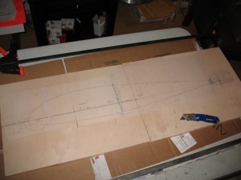
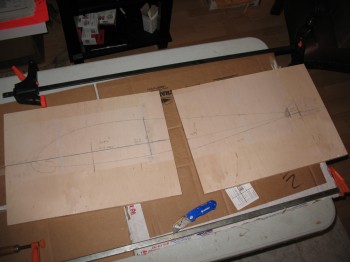
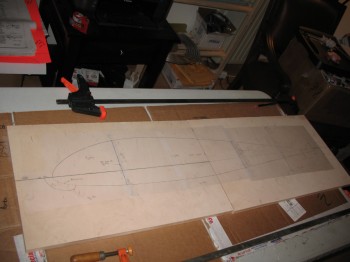
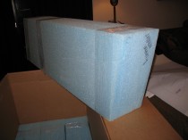
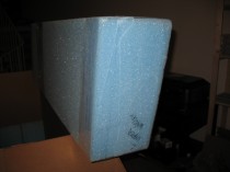
After I got the paper templates glued on (I used 3M 77 spray glue) and cleared the jigs and table out of the way, I pulled out the huge Feather Lite crate that contained my foam cores and began to unpack it and inventory the foam wing cores. As I stated a few days ago, I had been reviewing the plans since to get a decent idea of what I was looking at. It still took some time to figure them all out.
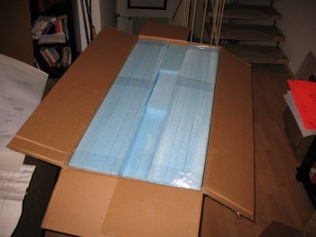
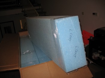
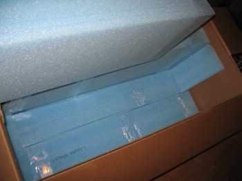
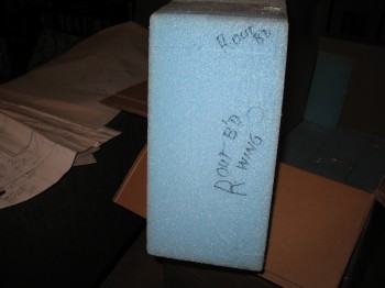
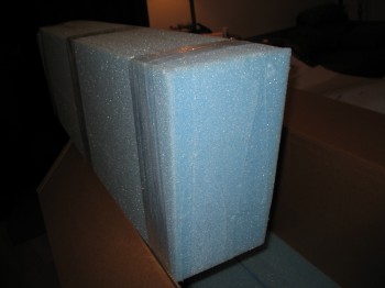

The Prime Directive during this specific task was DON’T DAMAGE THE FOAM CORES!!!
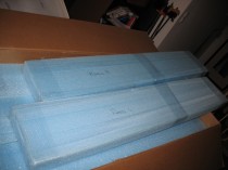
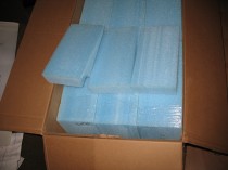

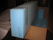
After I inventoried all the wing core pieces, it looked as though I was NOT going to need a hotwire saw to build the wings with what I had here. Remember, I left my hot wire saw in Virginia with my buddy Marco.
•••
14 July 2012 — Today I planned out & ordered some RG-58 coax cable as per Jim Weir’s instructions for constructing antennas for EZs.
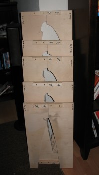
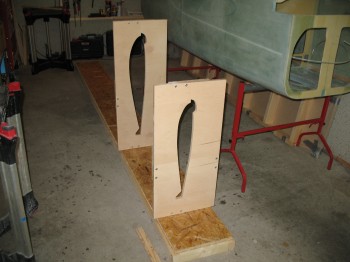
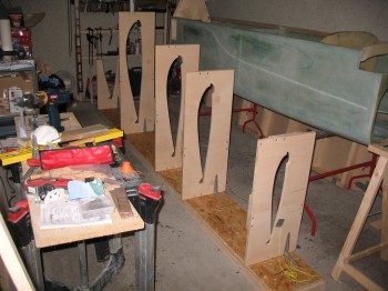
I also started working on the wing jigs. I cut out the #5 jig and the front sides of jigs #1-4.
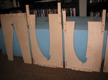
Once the jigs were cut out, I mounted the 1″ x 8″ brackets on the jigs with glue & wood screws. I drilled the two 1/4″ holes for the mounting bolts & wing-nuts but since I was using 3/4″ plywood instead of the planned 1/2″, I had to also countersink the bolt heads.
•••
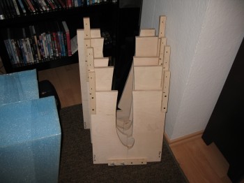
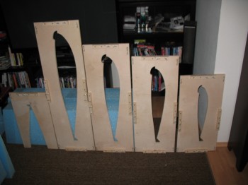
19 July 2012 — I took the remaining Trailing Edge Wing Jig pieces to the wood shop on Ramstein AB. I cut jigs #1-4 on the band, jig & table saws to produce their desired shapes. I then took the jigs home & finished them by drilling the holes, sanding and installing bolts, etc.
•••
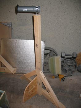
20 July 2012 — While I was at the DIY store I picked up a piece of PVC pipe to serve as my 3″ UNI tape roll dispenser for when I lay up the spar caps on the wings, CS spar and canard. I retired the spit posts and pressed one of them into service as the new 3″ UNI tape dispenser.
•••
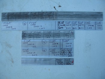
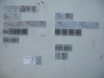
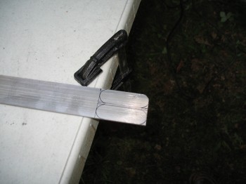
23 July 2012 — I cut all the aluminum extrusions (LWAs) for the wings, and well…. everything. Technically these are in listed Chapters 14 & 16.
•••
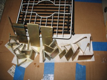
24 July 2012 — Finally got some Alumiprep to go with my Alodine! If I haven’t covered Alodine earlier, it is simply a corrosion protection application to keep aluminum (yes, aluminum does corrode!) from deteriorating and losing strength over time. This is especially important for composite airplanes where these metal extrusions are embedded into the foam & glass and cannot no longer be assessed or examined for any corrosion–for the life of the plane–without actually tearing into the glass to see it.
The Alodine process is fairly simple: the Alumiprep is an acid that does a super-scrub on the part to clean (etch) it. The part is soaked in Alumiprep for a couple of minutes. Then the part is rinsed off with water and put into the Alodine for a couple of minutes where it turns a greenish-goldish-brown & receives its corrosion protective coating. It’s rinsed with water once again and allowed to dry.
Click here for a good video showing How to Acid Etch and Alodine Aluminum.
I also found some Rosin Core Solder for the radio antennas that will be embedded in the wings, winglets & canard. Also had to pick up 2 more portable heaters at the base and press them into service.
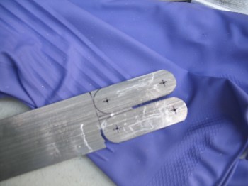
I used the Dremel & mini belt sander to make the 0.1″ & 0.2″ rounded-over edges on the aluminum extrusions. I also cut out & made the GIB shoulder harness seatbelt tabs.
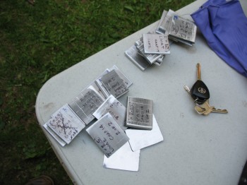
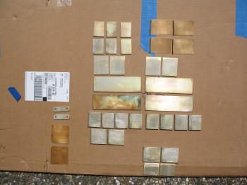
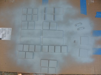
I Alodined all the cut aluminum pieces and set them up to dry. I had a sneaking suspicion that my Alodine was a little bit on the old side. No matter what I did, pre-cleaning, leaving the piece in either solution for significantly longer, it didn’t seem to change the intensity–either light or dark–of the Alodined parts.
 •••
•••
25 July 2012 — I took the now thoroughly dried Alodined aluminum extrusion pieces out to the back patio. I wasn’t overly thrilled with the quality of my Alodining process, so I decided to add another layer of corrosion control on the aluminum parts by adding a couple of coats of primer. But, to ensure that the glass would grip to a primer base that itself was gripped firmly to the aluminum surface, all the pieces will be lightly sanded and the prepped via a wash down with Simple Green and 3M pads to remove any “loose” and/or weak primer (this is how I prepped parts when I shot paint on my chopper project… Simple Green works great and is completely clean chemically).
After the parts dried for a few hours, I primed the other side of my aluminum parts.
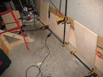
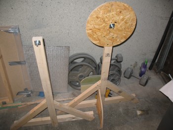
Then I started prepping for the Right Wing build. Since the garage floor is so uneven, I decided to simply build a wood base for the wing jigs.
 After the base was complete, I located it in the center of the garage and began the process of mounting the wing jigs to it.
 After I got the first few wing jigs mounted, I took a break to work on the main gear to get them knocked out.
•••
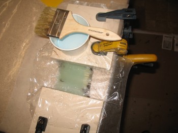
26 July 2012 — Since the main landing gear glass was complete, I turned my attention to the wing build. My first task was a 5-ply test layup for the 3″ UNI tape that is used in the wing, CS spar and canard spar caps. Over the years there have been different manufacturers & suppliers of this 3″ UNI tape, so to ensure the spar caps are the correct thickness, and thus the correct strength, the width of the UNI plies must be tested. This test layup procedure is spelled out in the Canard Pusher (CP) newsletter #25 on page 6. If the 5 plies are too thin, then the solution is to simply add more plies, which is also spelled out in the CPs.
 As my 5-ply test layup was curing, I went back out to the shop and finished mounting my wing jigs to the wood base.
 •••
•••