Chapter 18 – GIB Headrest/Turtleback/D-Deck
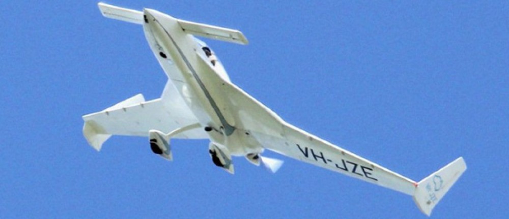
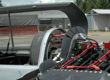
30 May 2013 — I had to run out & deliver some items I’ve sold online in prep for my move. Since it was in the latter part of the evening when I got started, I focused on planning out some details on what I call the “D-Deck,” the area at the aft end of the cabin, behind the GIB’s head, on top of the CS spar, and just forward of the firewall. Basically the rear passenger’s head rest area. I would like to build my canopy frame so that the frame continues past the aft edge of the canopy glass significantly farther than stock & have it intersect the firewall in much the same way as Wayne Blackler did on his Long-EZ:
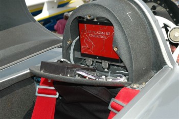
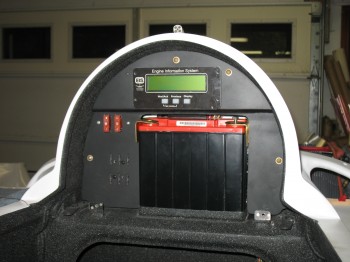
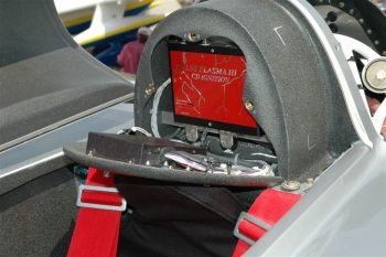
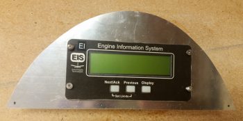
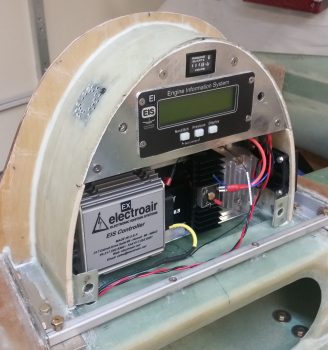
To me, this removes the cavernous area behind the GIB’s head, provides a headrest platform, and an area to hide away electronics (and the fuel tank vent manifold). Since I’ll be using GRT’s Engine Information System (GRT EIS-4000) I’d like to mount the EIS control unit in the D-Deck electronics area much like Nick Ugolini did (shown below, but without the spare battery) and as he discusses on his blog:
I’ll be honest, at first I didn’t like the thought of putting the EIS control head back in the aft of the aircraft. I didn’t really see the light until I spoke with a GRT rep at the Sebring LSA show and he asked me why I would want to mount it up front in a Long-EZ with all that engine probe wiring traversing a good total length of the fuselage (i.e. bad for space, current noise & WEIGHT). The GRT EIS control unit can really get away with one single wire feeding the EFIS all the engine info that is processed, tracked & displayed (which is a lot!). If one wants to be able to upgrade the unit at the front panel with a laptop connection, then they would require a whole ‘nother whopping second wire (vs. Lord knows how many by bringing all the probes up to the instrument panel). Thus, I get a well deserved “DUH!” on that one. Ok, GRT (and Nick) ya’ got me this time, but never again . . . ha!
I started measuring, designing and crafting my D-Deck electronics/fuel vent manifold housing.
•••
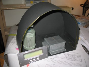
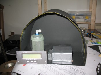
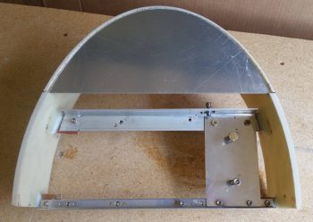
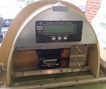
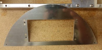
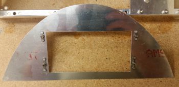
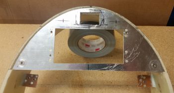
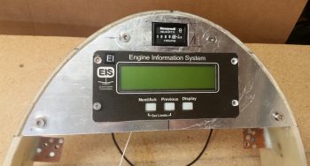
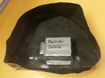
1-4 June 2013 — I finished my D-deck mock-up & then made some cardboard and duct tape mock ups of the Electroair Electronic Ignition controller. I placed the Electroair controller into the D-deck mock-up along with the fuel tank vent manifold and just the face-plate cutout of the GRT EIS-4000 control unit to see if there would be enough space. As you can tell, it looks like there will be plenty of room.
•••
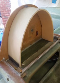
3 June 2018 — Today I finally cracked the code on the GIB headrest construction. I had pondered about its configuration off and on over the years since I knew I wanted my GIB area to be patterned after Wayne Blackler’s GIB headrest. No offense meant towards any Long-EZs out there, but the plan’s method of creating a cavernous amphitheater-looking structure back there was not something I liked in the least. Yes, Wayne’s version adds a bit more foam and glass, but I much prefer the look of Wayne’s GIB headrest/aft canopy structure vs stock plans.
I will say that my GIB headrest structure will be just a tad smaller than Wayne’s by about an inch around the sides.
Again, I pondered, dreamed and aspired to reach the . . . oops, different story! Ha!
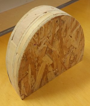
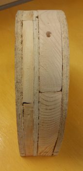
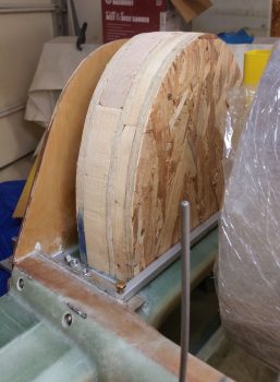
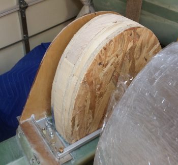
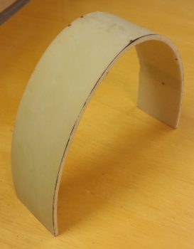
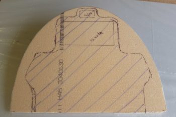
Yep, I wondered how the heck I was going to glass this structure while keeping its shape. Well, after spending a good 45 minutes finalizing how all the internals will fit, and using a very minutely modified version of the template that I created back in 2012, I simply cut out layers of scrap wood to create a form (or plug) for the foam.
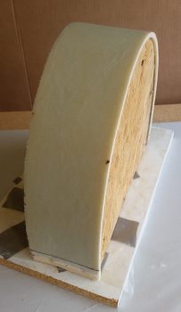
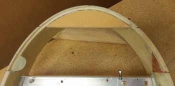
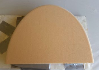
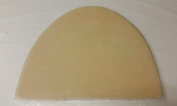
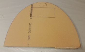
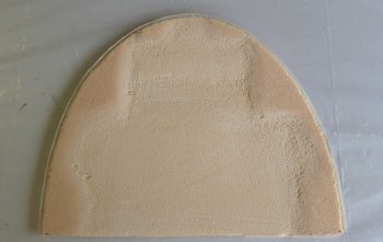
Since we’re not talking about a hugely robust nor super high strength structure here, and since space was fairly critical –not to mention in short supply!– I went with 1/4″ thick PVC foam for my GIB headrest structure. Moreover, the 1/4″ foam would easily wrap around the wood plug without cracking… and without any required cajoling (read: heat gun!).
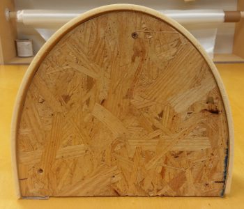
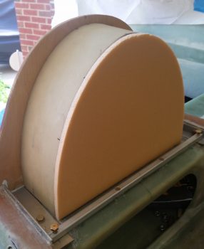
Just for fun, and to punk some GIB applicants [Final approval still pending . . . ] with my clearly comfortable headrest design <grin>, I did a quick mockup of the headrest plug. If you’re wondering why the plug is taller than the firewall it’s because I added heigh to it to make the sides a bit longer to allow me to secure the foam at the bottom of the plug with screws.
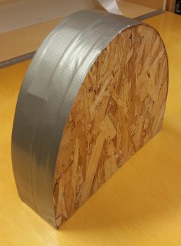
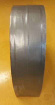
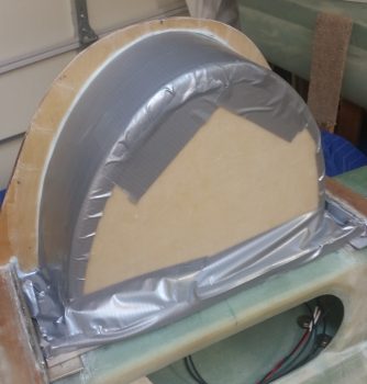
I then taped up the plug to protect it, but even more so just to level out the surface a bit.
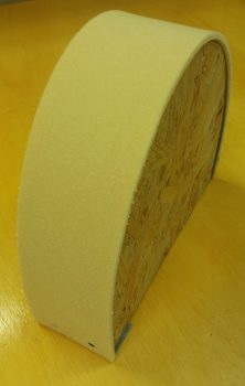
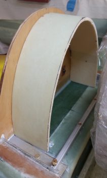
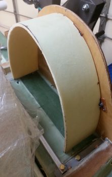
I then cut the 1/4″ foam and secured it to the form/plug with a couple of screws at the bottom on each side.
This front shot looks like the bottom edges distinctly curve in, but that’s a bit of an optical illusion since the camera is at a downward looking angle. Kind of a neat effect since the bottom edges are actually fairly straight!
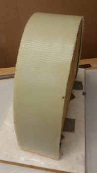
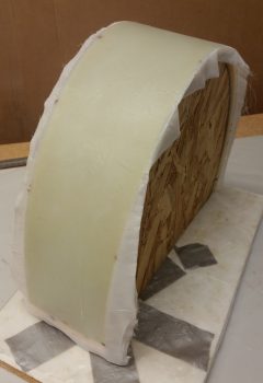
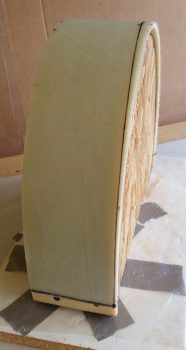
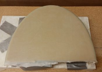
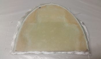
I then cut out and laid up 2 plies of BID on the GIB headrest foam. Boy, I’ll tell you, as an avid prepregger this free glassing stuff is for the birds! What a PITA! I thought I’d go ‘ol skool and just slap a couple of plies of glass on there . . . man is it high maintenance and finicky without that plastic keeping it all wrangled and in place.
Lesson learned!
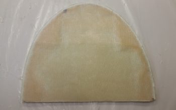
I then peel plied it of course. I took the pic above because I really do like the look of the non-peel plied weave in fiberglass, but when it comes to adding more plies, finishing and painting, it’s a pain to have to sand it to get the glossy cured finish knocked down… especially inside the weaves.
•••
4 June 2018 — Since I will have a myriad of electrical components housed in the GIB headrest, I am completing the task I started when I populated and configured the Hell Hole before mounting the firewall. The task here is to drill a wire transit hole through the top of the CS Spare (not the spar cap area of course) by first reinforcing the sides of the eventual hole with flocro, and then create the hole.
I started by identifying exactly where the wire transit hole was going to be located. My aim was to get it as close to the front right interior corner of the GIB headrest.
I then drilled out a good side sized hole ONLY on the top surface of the CS spar. I then dug out a good plug of foam to allow me to replace the foam with a 50/50 mix of flox and micro.
Here the flocro has been put in the hole and is curing.
I’ll jump ahead here well over an hour into the future to show that the flocro cured and I drilled a final 7/16″ hole through what will be the GIB headrest “floor.” The area surrounding the hole will get further reinforced with the interior 2-ply BID tape that I’ll layup when I glass the headrest in place.
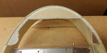
I then got to work on the GIB headrest. I pulled the peel ply and sanded the surface where any imperfections where apparent.
I then marked the glassed GIB headrest for cutting. The top depth is 3.6″ while the bottom depth is 3.9″.
After cutting the GIB headrest with the Fien saw, I then test fitted it in place.
Not shown is my spending about an hour measuring, test fitting, ascertaining, and determining final component placement inside the headrest. One thing became quickly apparent to me, and that was no further steps could really be taken on the headrest until the inside surface was glassed.
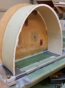
So I laid up 1 ply of BID on the inside surface of the GIB headrest, and then peel plied it. I then set the headrest back into place and taped the edges so that it was in what would be its final shape. Another view I didn’t capture on camera was that if the headrest sides weren’t kept in check, then they would splay outward. I figured an inside layup would keep the sides where they needed to be, and allow further interior component install steps to be taken.
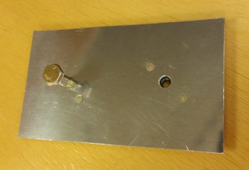
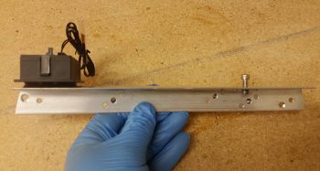
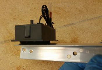
While the GIB headrest interior layup cured, I then cut the B&C recommended heat sink and mount for the SD-8 alternator’s voltage regulator. Again, according to B&C, a 0.040″ thick heat sink would do the trick, so that’s exactly what I used in the 2024 aluminum variant of metal.
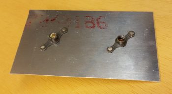
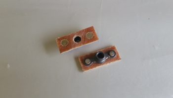
I then measured/added/riveted a couple of K1000-4 nutplates to the SD-8 voltage regulator heat sink mount for the SD-8.
Here’s the back side of the SD-8 heat shrink mount showing the nutplates riveted into place.
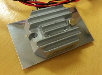
And a shot of the SD-8 voltage regulator being test fitted onto its heat sink mount. I think this heat sink mount should do the trick nicely.
A bit later I then pulled the peel ply and razor trimmed the edges.
As per my discussion, note how the interior layup allows the GIB headrest to maintain its appropriate shape.
I then set it back into place –sans any tape at the bottom edges– to check its fit. I have to say that I’m liking what I see so far!
[Note the position of the GIB headrest wire transit hole…]
•••
5 June 2018 — Today I wanted to take a big swipe at getting the internal components installation squared away on the GIB headrest before the structure gets glassed into place. Yes, I know! A bit of a rabbit hole to be sure, but yet just another sequencing thing that if done now will make the build progress much easier in the long run. Definitely worth a 2-day detour in the grand scheme of things.
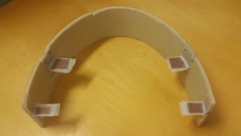
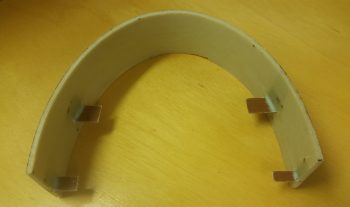
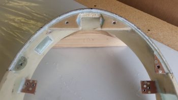
I started by checking, cross checking and double checking a myriad of final layout measurements. I then cut out 4 each 1/16″ thick phenolic tabs for mounting aluminum angle cross-headrest mounts. I then measured, marked and cut slots for the phenolic mounting tabs into the inner surface skin of the headrest. I dug out the foam so that the outboard edge of each mounting tab sat flush against the interior surface of the outer skin.
Once all looked good, I sanded both sides of each phenolic mounting tab rough, flocro’d them into place and then laid up 2 plies of BID on the front side of each tab, and 1 ply on the aft side of each tab. I then peel plied the layups, and after the tabs looked like they were set in their final position I took off to grab some supplies for glassing the nose and canopy, and to run a couple of errands (they weren’t set completely… and a couple moved a small amount on me).
A couple of hours later, after I returned from my mini-sojourn out, I pulled the peel ply and knife trimmed the glass edges.
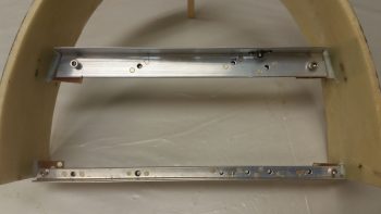
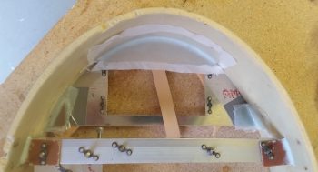
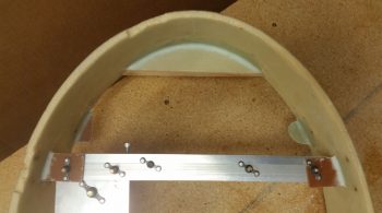
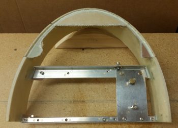
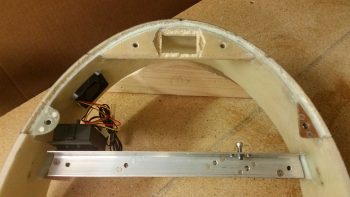
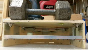
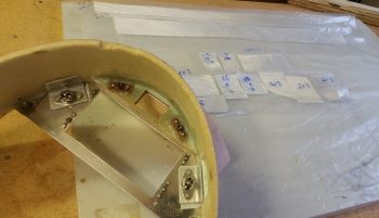
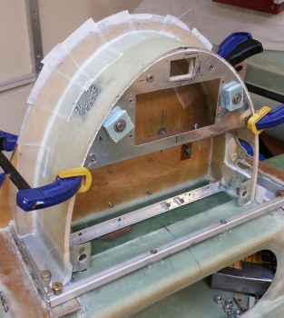
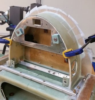
I then spent the next 5+ hours finalizing the position of both angled aluminum mounting brackets, the respective components and the mounting bolt positions as I slowly drilled and riveted a BUNCH of nutplates into place. Here you can see the backbone of the mounting setup in the GIB headrest: the top and bottom 1/16″ aluminum angle.
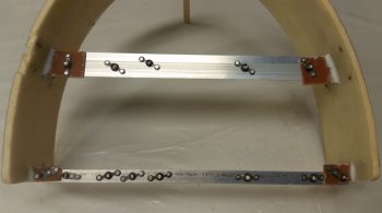
Here’s an aft view of the top and bottom aluminum angle mounting brackets with a bunch of nutplates riveted into place. Quite obvious I guess, but for me personally I don’t want to mess around with the initially easier task of simply drilling a hole then using a nut & bolt to hold a component into place… I want to remove the nut from the equation and simply have to worry about the mounting bolt and that’s it.
Speaking of bolts. Since the access to the bolts around a good many of these components is very restricted, I opted to go with hex cap head screws that use an allen key for installation/removal. Maybe it’s just me (I’m sure it often is!) but driving small diameter bolts/screws into nutplate assemblies with a screwdriver is just not an optimized endeavor and the amount of pressure required to avoid stripping the phillips portion of the screw head borders on just plain silly.
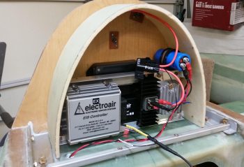
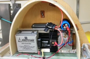
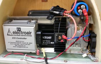
After getting the first round of #8 and #10 nutplates riveted into place, I then did a test mount of a bunch of the internal GIB headrest devices. Note that this round of components all sit just forward of the two firewall face mounted MAP sensor boxes.
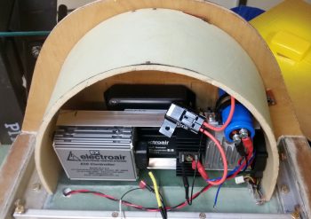
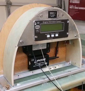
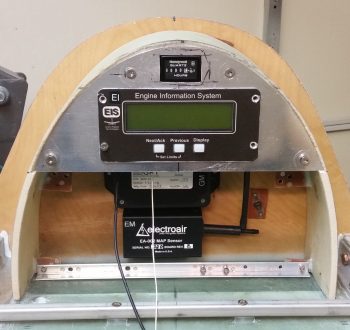
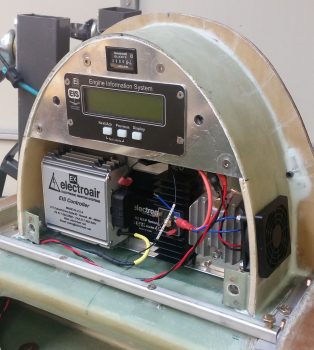
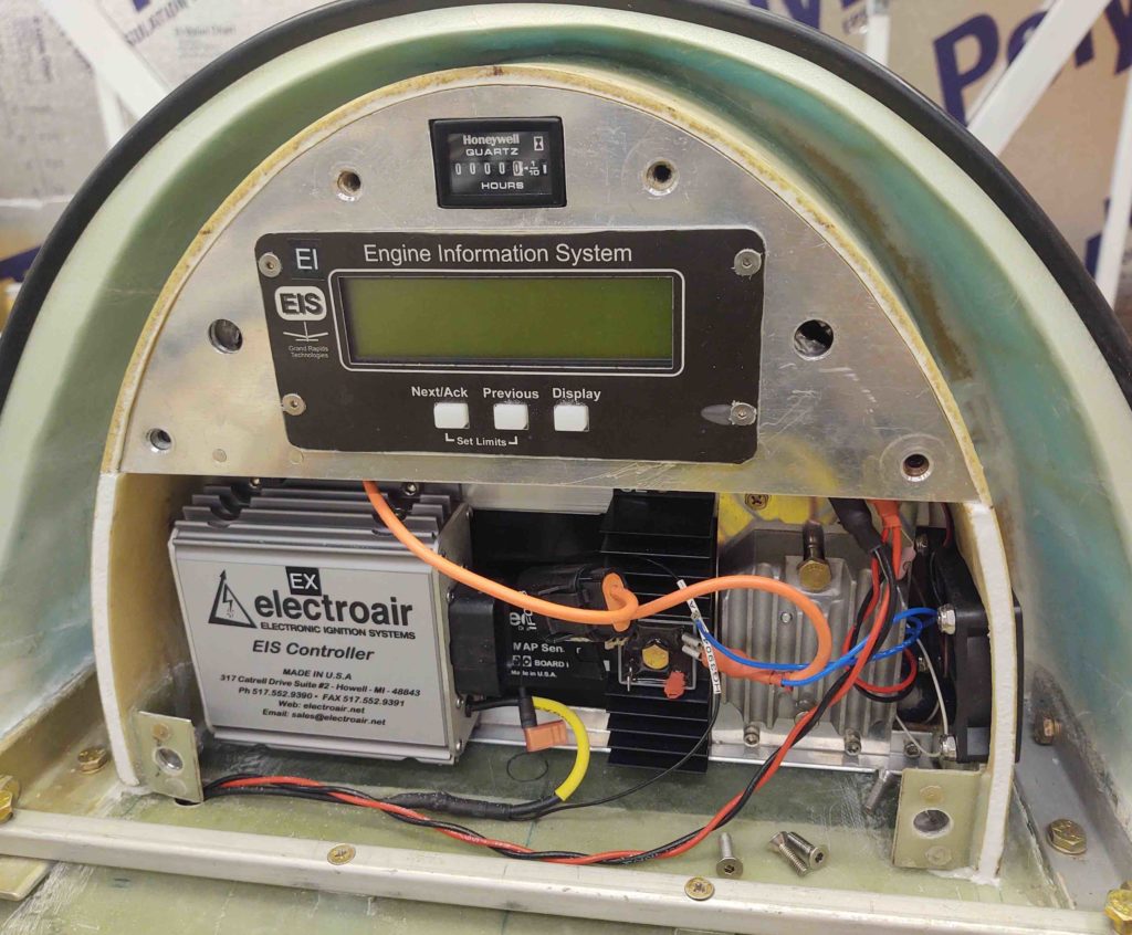
The components installed so far are as follows. Back row: GRT MAP sensor (top) and Electroair EI MAP sensor (bottom). Front row (l to r): Electroair EI controller, SD-8 backup alternator self excitation module (black heat sink), SD-8 voltage regulator mounted on 0.040″ thick heat sink plate, and SD-8 capacitor (big blue D-cell battery looking thing).
In the next pic after this one below I set the intake cooling fan in place, on the left (aircraft) side of the headrest next to SD-8 voltage regulator. The smaller exhaust fan will be installed at about the 10-11 O’clock position when viewing the headrest as below. Also, I clearly haven’t found a home yet for the rather robust inline 15 amp fuse (orange leads).
As you can see, it’s pretty tight quarters inside the ‘ol GIB headrest, and there still a number of components left to be jammed in there! If you’re good at games like ‘Where’s Waldo?’ then you may have noted that I added the cooling fan into the mix, in the lower right hand corner (of the pic)…. actual left hand corner of the headrest.
Here’s a view from a higher up angle . . . again note how it makes the headrest structure appear very round! Also, if you hadn’t noticed it already, take a look at the red & black twisted pair wire exiting the GIB headrest structure via the wire transit hole. Just an example of how the wires heading to the hell hole or points forward will exit the GIB headrest.
Engine specific wiring will exit through the firewall in one of two pass-thrus, situated in the respective lower aft corners of the GIB headrest . . . coincidentally, that’s why the MAP sensors are center mounted, to allow open wire paths to remain clear in both aft left and right sides corners of the GIB headrest.
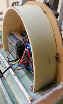
And a side view showing a bit of depth on the installed headrest components so far.
•••
6 June 2018 — Today was another focus on the GIB headrest. I started by finely sanding the front edge of the headrest so that it was even around the front edge perimeter.
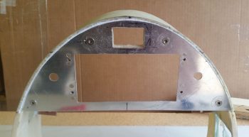
I then set about determining the size and configuration of the headrest’s top plate, which I cut out of 0.040″ thick 2024 aluminum plate. I then marked and cut a groove into the top half edge of the headrest that the top plate sits, and is mounted, recessed into… which is why I wanted the front perfectly “square” so that I could recess the top plate vertically, while the front of the headrest edge “leans” slightly aft being 3.9″ deep at the bottom base and 3.6″ deep at the top. If you’re wondering, the aft edge of the headrest is vertical and straight.
I then measured out, marked and cut a mounting hole for the GRT EIS4000 control unit. Of course I wanted to see how it looked, so I mocked it up in the headrest and set the headrest in in place.
I then knocked out riveting the four #6 nutplates for mounting the EIS4000 to the headrest top plate. I had to use the miniature version on the top holes so that the rivets wouldn’t peak out above the EIS4000’s mounting flange. I will be painting this top plate, but I still didn’t want to mess around with covering up any rivets if I don’t have to.
I then tried out the nutplates by test mounting the EIS4000 into the headrest top plate… thankfully it fit fine and no issues.
I then glassed a piece of 3/8″ foam into the top of the headrest arch, and some scrap pieces of phenolic and G10 –respectively– inside the upper headrest sidewalls . . . all which will serve as screw mounting points to secure the top plate to the headrest. I used 2 plies of BID and started the layups on the aft side of the screw mounting tabs. I taped up the top plate and used it as a type of jig to keep the tabs set at the right configuration, aligned evenly with the front edge of the recessed edge, not the front edge of the headrest.
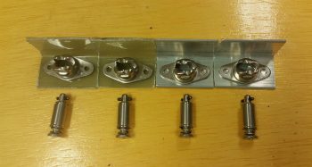
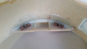
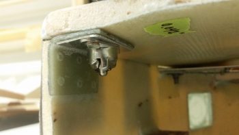
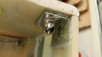
As the layups above cured, I got to work locating and cutting both glass and aluminum mounting tabs for the 4 CAMLOC receptacles that will be used to secure the headrest front cover (not top plate) in place.
A bit later I pulled the peel ply and knife trimmed the 3 layups for the headrest top plate screw hard points.
Here’s the front side of the headrest showing the glassed in place screw hard points.
I then cut a very small trench in the foam around the perimeter of the front side of the top plate screw hard points and recessed inset. Before I then laid up 1 ply of BID just inside the recessed inset where the top plate will get mounted into, I filled the trench with thick micro. I then peel plied the layup(s).
Here’s a closer shot of the glassed front side top plate inset and screw mounting tabs.
•••
7 June 2018 — My plan was to work about half a day on the headrest and then get it glassed into the fuselage and move on . . . that did not happen.
I started off by cutting out the front face cover of the headrest out of 3/8″ thick PVC foam and then carefully sanding it so that the cover’s edge was just slightly smaller than the headrest’s, to allow for the thickness of the glass.
I then rounded the edges of the headrest front face cover piece.
I then glassed the front headrest cover piece with 1 ply of UNI with the fibers running horizontally and then 1 ply of BID on top of that. I will say I finagled with the edge for a time to get the glass to lay down as nice as possible around the edge. I peel plied the cover layup and let it cure. I will also note that because of my aforementioned aligning issue with the right engine mount extrusion, I had to add a small strip of foam on the bottom edge of the right side.
Barely visible in the pic below is an added set of #8 nutplates on the upper angled aluminum crossbar mount tabs sticking out from the sidewalls. I’ll point this later on, but these are for a pair of #8 CS screws –one each side– that actually hold the crossbar in place, since the bigger #10 screws that previously held on the crossbar did double duty and also held the SD-8 heat sink mount and Electroair controller in place, respectively. If I removed either of the #10 screws to remove either component, I was unhinging either side’s mounting point of the crossbar. These #8 CS screws allow the mounting crossbar to be held in place regardless if components are installed or not.
I then got to work on the headrest top plate. I drilled, counter sunk and riveted in the nutplate assemblies for the lower top plate mounting screws. I had to go one size up than I had planned, to #10 screws, since I am rapidly depleting my nutplate bench stock!
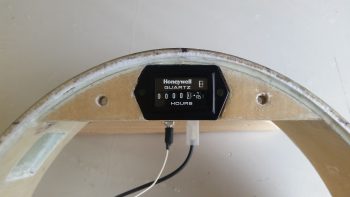
Also, I measured, marked and cut out a rectangular window above the EIS4000 cutout for the Hobbs meter to peak through.
Here’s a quick mockup with the Hobbs meter now visible and the EIS4000 set in place. Note that the EIS4000 screw holes have been countersunk so that the screws will sit as flush as possible. Also note that I drilled and countersunk the top #10 screws for the top plate, although the nutplate assemblies have not been floxed into place yet.
I then set the mocked up top plate & headrest into place on the fuselage. I have to say I’m very pleased with how the headrest is coming along, although it is taking a bit of time to complete.
When the GIB headrest is glassed into place on the fuselage, I want it to be as complete as possible with all components, no matter how minor, small or “important” to be accounted for and set in position. Thus, I had been mulling over where exactly to place the very lightweight cooling fan thermal control unit in this matrix inside the headrest.
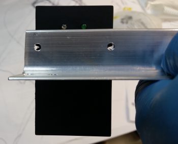
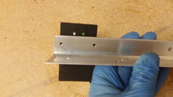
I decided that it would go on the right side, mounted to the upper mounting crossbar, adjacent to the interior right headrest sidewall. I decided to use velcro to secure it in place, but wanted something a little bit more secure as well. So I drilled 2 small holes in the top of the angled aluminum mounting crossbar and then notched the flange on the cooling fan control unit to match the holes. This way I can use a piece of cable lace to positively secure the cooling fan control unit in place in addition to the velcro.
Here’s another shot of the cooling fan control unit held in place with velcro with the 2 wire lace holes visible. Note that the operating LED indicators are located on the forward side of the mounting crossbar, so that they will be visible with the headrest front cover removed.
This shot shows how it will look when mounted inside the headrest.
And just a final closeup of the cooling fan control unit mounted in place with velcro.
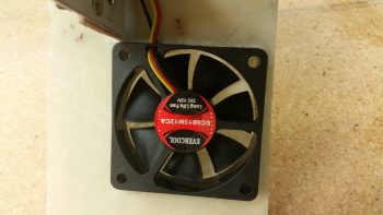
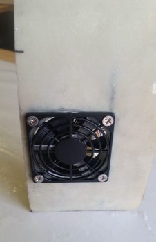
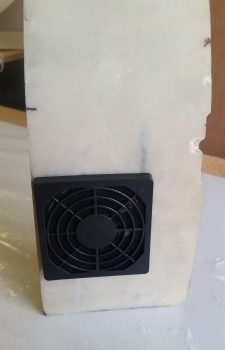
With the cooling fan control unit mounting squared away, it was time to turn my sights on the fans themselves. I have one 60mm cooling fan that blows external air into the headrest, and is positioned –not coincidentally– right next to the SD-8 voltage regulator. It also is positioned so that it blows cooler air right down the row of bottom mounted components in the headrest: SD-8 voltage regulator, SD-8 bridge rectifier (mounted on a heat sink) and the Electroair EI controller, all which have cooling fins to facilitate cooling during normal operations.
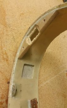
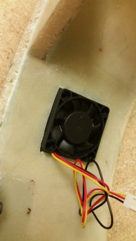
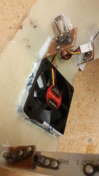
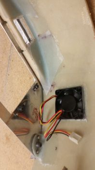
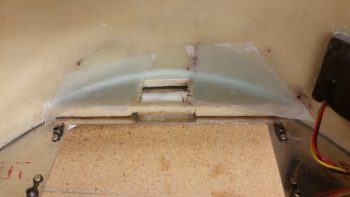
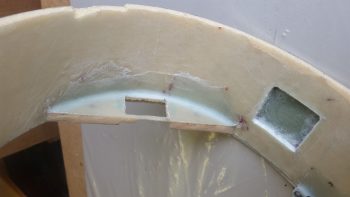
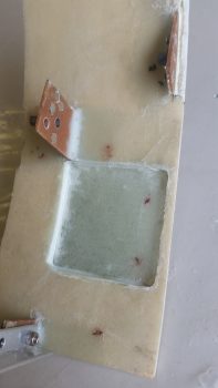
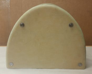
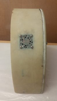
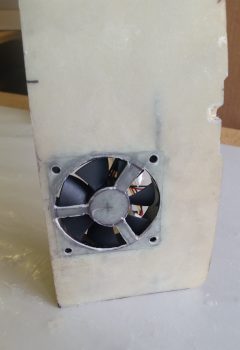
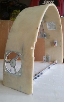
I then have a 40mm exhaust fan to remove all the warmer air from the headrest housing. It’s positioned on the high side (warm air rises) at about the 10 O’clock position when looking straight at the front of the headrest. Since I did not want to have the air flowing through thick cutouts into the headrest sidewall, I decided to simply place the exhaust fan as flush as possible with the external glass of the headrest. To do this I clearly had to remove the internal sidewall glass and the foam in between, as I did below.
This allowed the exhaust fan to sit right against the external headrest glass, and reduced the footprint of the exhaust fan considerably by embedding it in the sidewall.
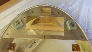
This pic actually shows quite a bit. You can see the cooling fan controller unit mounted in place with velcro atop the mounting crossbar. It also shows the position of the embedded exhaust fan. If you look at the glassed in foam reinforcement piece at the top of the headrest arch, you’ll see the foam and glass dug out to allow for the Hobbs meter to be set down below the surface of the top plate, slightly embedded as well. Finally, if you look closely you can see the #8 CS screws in place on each end of the angled aluminum mounting crossbar, securing it in place.
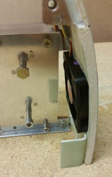
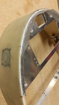
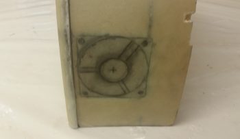
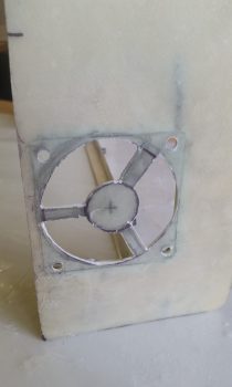
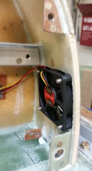
I honestly hadn’t planned on embedding the larger 60mm intake cooling fan but since I needed clearance for the headrest cover mounting CAMLOC tab just below the fan, it required me to move the fan up as far as possible. With the fan surface mounted on the inside headrest sidewall, I couldn’t move the fan up since the SD-8 heat sink mount interfered with any upward positioning of the fan. The only way that I could keep the fan in its optimized position for cooling the lower air-cooled components was to embed it in the sidewall as well, which allowed me to position it farther up and still provide clearance with both the SD-8 heat sink mount and the front cover CAMLOC mounting tab (shown set in position).
Yet another view of the embedded intake cooling fan.
And the notched sidewall glass for the embedded intake cooling fan.
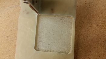 I then glassed in a square piece of BID that made up the “floor” of the cooling fan notches, and then added another piece of glass that actually covered the micro’d recesses I created on the sides of each notched hole. I figured this would added a little strength back into the headrest structure at minimal weight. However, this created a potential fitting issue if the glass on each side decided to be a bit thicker than required. Also, to help keep the glass along the narrow edge of the sides of the notched holes, I simply taped up the fans to protect them and then inserted them into place to keep the glass positioned correctly.
In the pic of the exhaust fan above, and below, are 1-ply BID reinforcement layups that I glassed in on the back side of the top plate reinforcement structure. With the big hole that I dug out on the front side for embedding the Hobbs meter, I decided to add a bit more structural strength on the back side. I can’t really add any glass on the front side since it would push the top plate out of position.
During the placement, sanding and alignment of the top plate, the interfacing edge of the headrest structure –being just foam– has been reduced to a narrow strip. To get the foam edge back to its original thickness, provide a more seamless edge with the top plate, and to a degree finish the edge for paint, I decided to tape the edge of the top plate and then lay in a small bead of flocro along the headrest edge adjacent to the top plate edge.
I then pulled the peel ply and razor trimmed the glass along the aft edge of the headrest front cover. I will need to do some clean up sanding and aggressively sand along the edges to get a few bumps and slight irregularities knocked down in place.
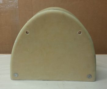
Here’s the aft side of the GIB headrest face cover plate. Note that I will make some depressions in the aft side face before I glass it to ensure clearances with the internal components of the headrest, specifically the buttons on the front of the EIS4000 unit… which currently sit recessed below an imaginary line drawn across the face of the headrest’s front edges, but just barely.
•••
8 June 2018 — Today was pretty much a full day on the GIB headrest structure again.
I started out by pulling the peel ply on the top plate reinforcement layups and trimming the glass. I also pulled the upper exhaust cooling fan out of it’s recessed notch in the sidewall. It took a bit of convincing, but I finally got the little fella out of the glassed notch.
The same was true for the larger intake cooling fan, although it did come out a lot easier than the little fan. I will say that the layups inside both the fan notches look good and will definitely do the job.
One task I did last night but failed to mention, probably because I didn’t have a pic of it, was creating flox hard points in the depressed foam sides for the Hobbs meter mounting screws. Here you can see that the hard points are cured. You can also see I lost a bit of foam off the front strip, which I will glue back into place.
I then test fitted the Hobbs meter, which fit snuggly but just fine.
I then made up 2 K1000-3 nutplate assemblies for the top plate upper mounting screws.
I then floxed the nutates in place and secured them with 2 spare AN3 bolts.
I then marked up the aft side of the foam headrest cover piece to depict what area(s) would get sanded down to create a depression in the foam. The areas not sanded down or depressed are the portions that interface with the front edge of the headrest structure, and/or the parts that press up against the CAMLOC mounting brackets.
I then took the foam headrest cover piece outside and spent about half an hour sanding down the marked areas into a nice depression about 0.070″ deep. When I brought the cover back inside the shop, I then cut a trough all around the edge of the glass to create a micro corner when it gets glassed. To be clear, I didn’t use flox in the trough since this piece is not a structural component of the aircraft.
I then laid up 2 plies of glass on the back side of the GIB headrest cover piece. The first ply covered about the bottom 2/3rds of the cover while ply #2 covered the entire aft headrest cover. I didn’t feel that peel ply was required on the aft side of this cover, so in rare form I didn’t use it.
I typically take Friday nights off, which I did tonight to again hang out with my buddy Rob for some beers and dinner.
When I returned I trimmed the cured glass on the aft side headrest cover layup. The layup looked fine and I’m pleased with the results.
I of course then had to check it out to see how it looked. Not bad!
•••
9 June 2018 — Today I went back to my blog to refresh my memory to see how I installed the CAMLOCs when I put them in for the pilot’s seat thigh support. In my own blog I mention not having the correct rivets on hand. And I’ll be darned if I never ordered those correct rivets!! Argh!
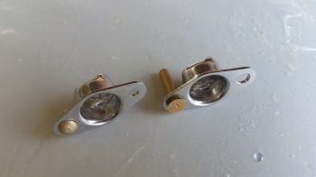
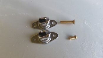
The only 1/8″ rivets I have on hand that would work in general are button head rivets, and for installing the CAMLOC receptacle brackets for the headrest cover I definitely needed countersunk head rivets. Since I have the much larger 5/32″ rivets on hand, which are fairly long as well just as a point of note, I decided to use them instead.
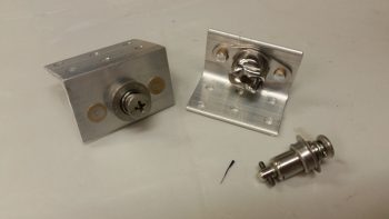
This of course meant drilling each lightweight STAINLESS STEEL CAMLOC receptacle (these are actually a SkyBolt product btw) to widen the rivet mounting holes from 1/8″ to 5/32″ diameter. In the end it really wasn’t that difficult. The only negative was that I set the 5/32″ drill bit down for a second conveniently located right next to the 11/64″ bit… which is what I of course grabbed to drill the wider rivet holes! DOH! Oh, well, a few thou more of play but they still worked fine.
Here you can see the differences in rivet size. Of course I ended up cutting the length way down on the 5/32″ rivets.
After fiddling about with getting the cover in the best spot (there will be some trimming of the cover along the edges), I prepped the lower CAMLOC brackets and floxed them into place.
Here’s the right side lower CAMLOC bracket to secure the headrest cover into place.
And the left side.
I then made up/prepped the 2 upper CAMLOC receptacle bracket assemblies only this time I used 1/16″ thick angled aluminum for the brackets.
Here we have the GIB headrest faceplate cover held in place with the 2 lower installed CAMLOC assemblies.
Here I’ve simply slid the top CAMLOC studs (which I will need to order longer ones for the top) in place for this pic.
I then spent a little bit of time drilling the vent holes for the upper cooling fan (exhaust). I know the holes may look like I drilled them willy-nilly, but there is actually a pattern that follows the configuration of the fan to optimize airflow out of the headrest structure.
Since it was fairly late, I couldn’t fire up my Fein saw, so I’ll get to cutting out the sidewall glass for the lower intake cooling fan tomorrow. I did mark it up in prep for that.
•••
10 June 2018 — After grabbing some lunch and returning home, and unloading the goods, I then got busy on finishing up the final few tasks I needed to that would allow me to glass in the GIB headrest.
First up was cutting out opening in the left headrest sidewall for the cooling fan intake. I also drilled the corner holes for the mounting screws as well.
I then test-fitted the cooling fan.
And then tried out a mocked up installation of the cooling fan inlet cover bracket.
I then snapped the inlet cover/filter element into place. Looks like this will work just spiffy!
Here’s a rather artistic shot (ha!) of the 2 cooling fan mounts.
Another shot just showing the CAMLOC mounting through holes in the headrest top plate.
I then prepped and floxed in the upper CAMLOC brackets for securing the GIB headrest front cover. As you can see by this pic, I had taken it a bit later after actually all the floxing as I had since cut out all the glass (BID) required to glass the headrest structure into the fuselage, on the front face of the firewall.
To flox in the upper CAMLOC brackets I had to use a scrap piece of glassed 3/8″ foam on each side to keep the bracket tight against the backside of the top plate.
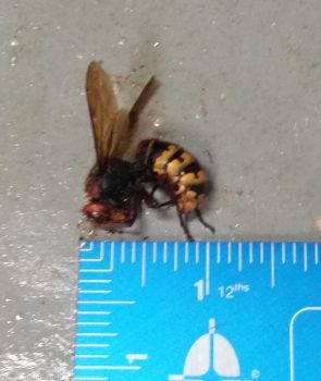
As I was prepping to whip up some epoxy for glassing the headrest into the fuselage, a giant hornet flew into my shop and started buzzing around (I’m guessing that’s what it is, to be honest I don’t know the true taxonomy of this insect…) I was willing to let his trespassing into my sacred shop go unchallenged, but he then entered into a fairly aggressive posture, forcing me to employ countermeasures! I hit him with a few shots of Simple Green, wetting his wings down so he death spiraled to the floor…. the death part of that action coming from my shoe compressing his earthly form into the concrete underneath! In short, I killed the obnoxious little bastard . . . (ok, actually quite huge!)
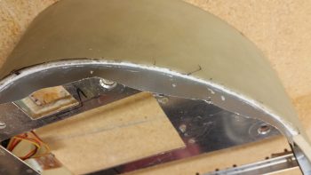
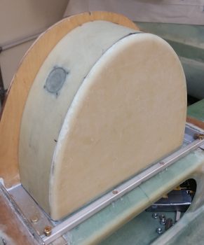
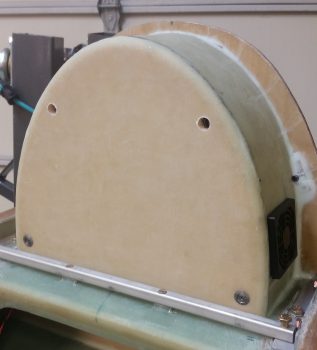
So over 2 hours later this is what popped out the other end of the night’s endeavor: one GIB headrest, floxed and glassed in place on top of the CS Spar and on the front side of the firewall! (…. yay!)
Here’s a shot from the other side.
•••
11 June 2018 — Today I started out by pulling the peel ply and cleaning up the layups securing the GIB headrest to the fuselage, specifically to the front side of the firewall and sitting atop the CS Spar. Rest assured this was no quick effort, and took well over an hour to complete.
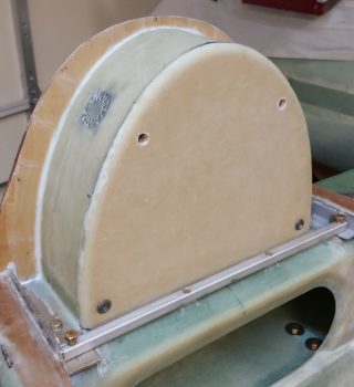
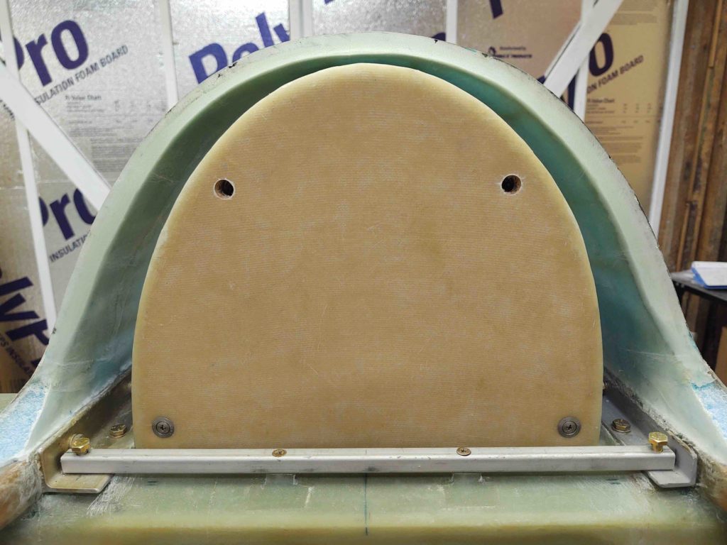
I then attached the headrest cover in place with the lower 2 CAMLOCs (Late last night I figured out the stud lengths I need to acquire for the top set) and was quite pleased at the fit and finish of the cover.
As I was trimming the internal headrest layups, I mounted stuff to make sure it all fit. Here I test mounted the cooling fan after removing a decent sized piece of glass overhanging the bottom edge of the fan notch in the sidewall. I also took the opportunity to test out the length of the new SS CS mounting screws I picked up for its installation.
With both fans installed, I also took the opportunity to reallocate some wire from the smaller exhaust cooling fan to the larger intake cooling fan to allow the latter’s wires to reach the right-side mounted fan controller.
I then spent a bit of time doing some final assessments and measuring before I pulled the trigger and drilled the firewall pass-thrus in the lower outboard corners of the GIB headrest.
I had some errands to run and a few personal things to get done, so while I was out I picked up some more hardware for the headrest components. When I returned I installed just about everything in the headrest for the first time all together.
I then test fitted the front cover with ALL the components inside… still fit like a champ!
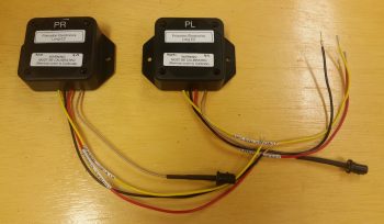
I wasn’t able to fit the set of the fuel probe control heads into the GIB headrest structure… yet. Simply due to lack of space.
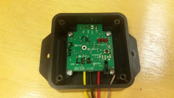
However, looking inside the fuel probe control boxes I noted that the control board is fairly small compared to the actual box its mounted inside. I’m thinking I may remount the control board in a smaller form factor that would allow these units to be mounted inside the GIB headrest…. since it really would make for easier wiring, integration, etc.
NOTE: The lack of space in the headrest/D-Deck could not be overcome, any way I sliced it. Thus, these fuel probe control heads ended up in the Hell Hole.
Since the GIB headrest is pretty much finished I had to say goodbye to some old friends that have been hanging around since 2012. I made these guys up to check fitting and configuration on the GIB headrest internals long before I really had anything other than the basic airframe components on hand. These guys sure have been useful over the years, but I certainly don’t have a need for them anymore since the real versions are on hand and installed in the fuselage!
I then taped up the GIB headrest and immediate surrounding area in prep for canopy installation/construction/glassing.
•••
10 August 2020 — As I get my “sea legs” underneath me, moving back into the realm of airplane building, I both want to get some low hanging fruit knocked out as I also assess my plan of action.
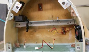
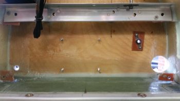
One thing I’ve really needed to do was to crack open the engine electrical components’ compartment (AKA: “GIB headrest”) to check for any corrosion from the many miles of road traveling this fuselage has done, and also its sitting inside non-temp controlled facilities during two different storms.
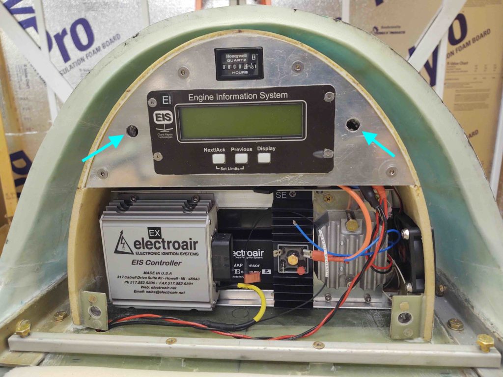
My #2 reason for cracking open the GIB headrest compartment is that you’ll note it is supposed to be attached in place by 4 CAMLOCs…. the upper 2 being MIA. That was simply because I had all 4 of the same length, but the top two needed to be just a tad longer. I had them on hand before I moved, but . . .
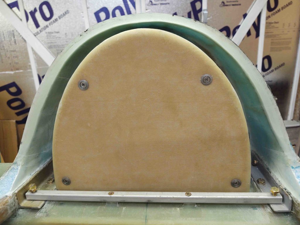
… the upper faceplate through-holes were too small {blue arrows}. I finally got around to using the Dremel Tool with a small sanding drum to widen each hole by about 0.050-0.070″ in diameter, at which point the CAMLOCs fit through and into their respective receptacles nicely.
Also note: although there was a bit of dust inside the compartment looked nice and clean with no noticeable corrosion anywhere.
And here we have the upper CAMLOCs in place, making the GIB headrest compartment plate attachment official ….
•••
25 August 2020 — Today I worked on the D-deck/Turtledeck/GIB headrest.
I have 2 slide switches and one D-Sub connector to install, to allow me somewhat easy access to them. One of the slide switches and the D-Sub connector are for the P-Mag EI.
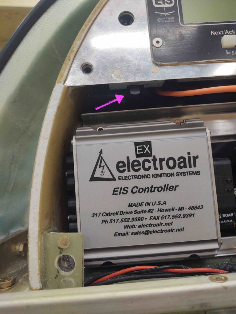
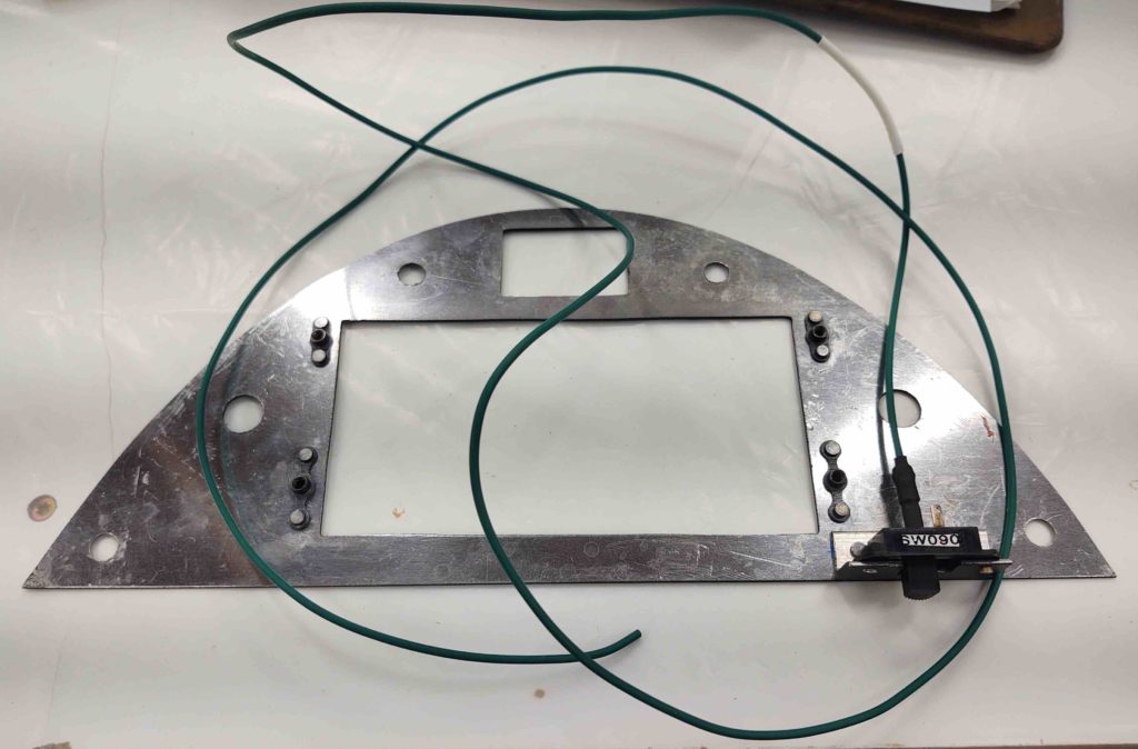
The other slide switch I’ve installed here (actually just the switch bracket at this point), which controls the on/off for the Electroair electronic ignition manifold pressure (MAP) signal. Having this switch can be very useful for troubleshooting potential EIS issues, so I installed it onto the upper D-deck faceplate.
Here’s a final shote of the upper D-deck faceplate before it goes in for paint . . .
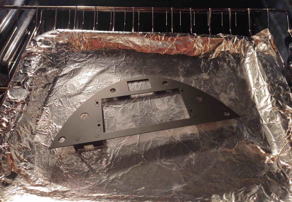
Which just happened. I followed Nate Mullins’ paint protocol here and baked this sucker at 175º F for about an hour.
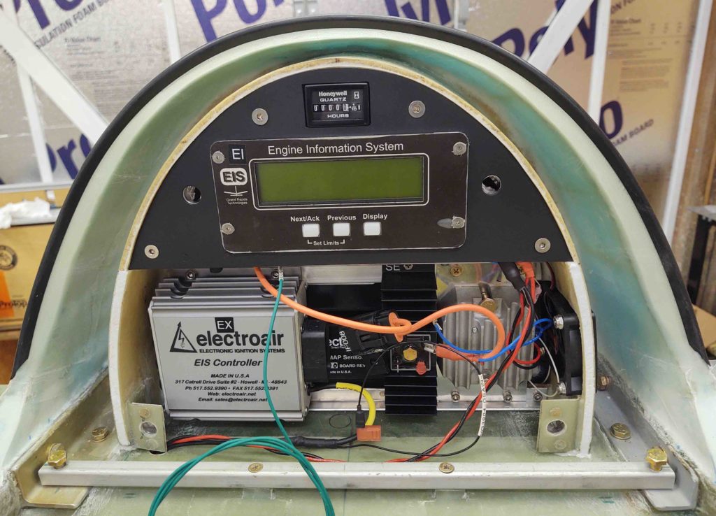
I then installed the actual Electroair electronic ignition manifold pressure (MAP) signal switch [sw090] onto its bracket.
And here’s the new look, with functioning switch in place.
Also note that with some left over micro I dug out the foam on the lower front edges of the GIB headrest housing and filled it in… looks much better IMO than bare foam.
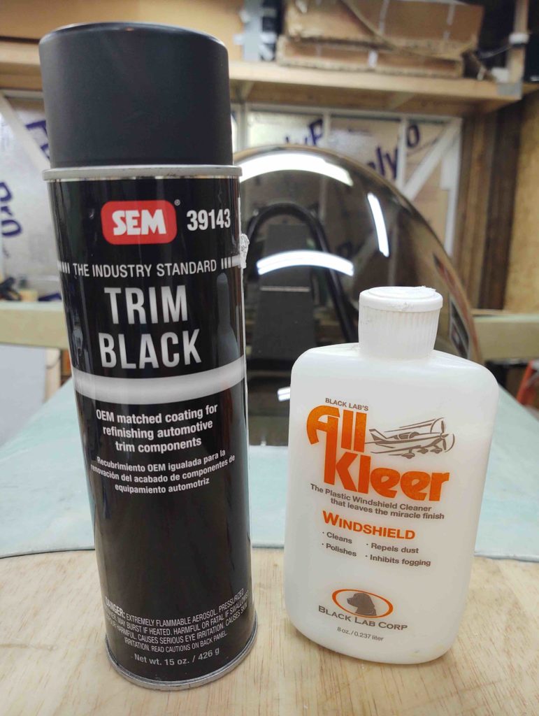
If you’re curious about Nate’s paint choice for panels, assemblies, etc., here it is. SEM Trim Black… which is a flat/matte black.
Also, if you’re curious about what I used to clean the canopy, here it is as well.
