
Chapter 9 — Main Landing Gear, Axles, Wheels & Brake Assemblies
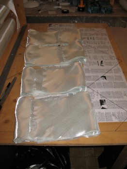
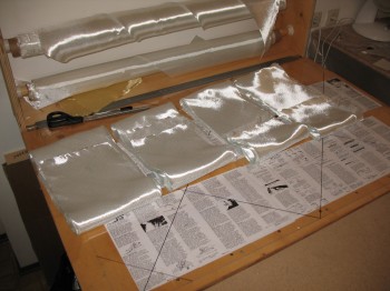
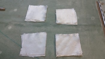
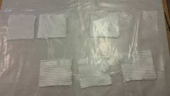
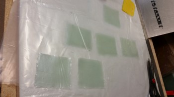
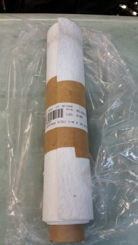
30 June 2012 — With my consoles mocked up and my seatback cut, I’m done with my temporary diversion and am ready to start back in order with the plans. The next task up on the order of battle is the Main Landing Gear. I had been reading up on the landing gear build steps in Chapter 9, so I was ready to get moving on the first step, which was cutting glass for the gear legs. And I don’t mean SOME glass, I mean A LOT of glass. 16 pieces all told at 30-40°across the whole width of the UNI roll.
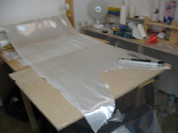
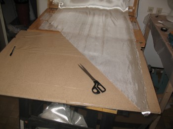
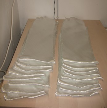
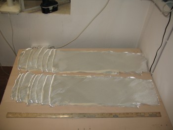
The final tally is 4 sets of 4 each UNI strips, 9″ wide at 30-40°.
•••
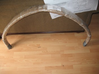
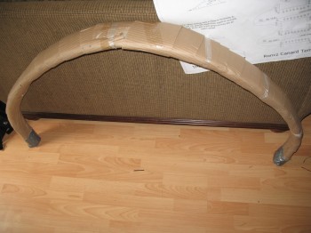
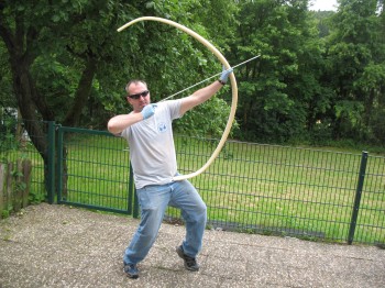
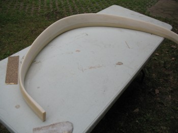
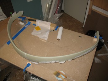
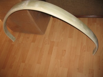
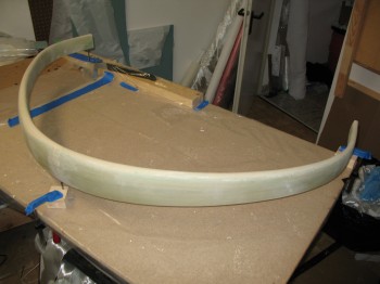
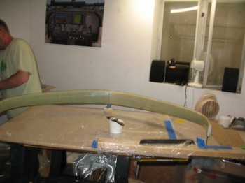
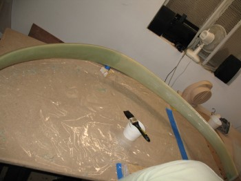
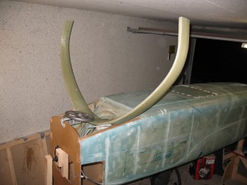
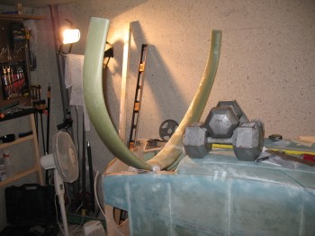
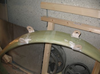
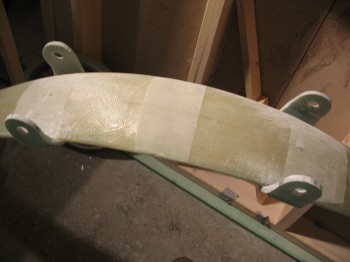
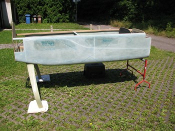
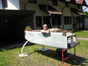
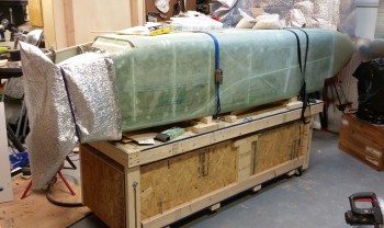
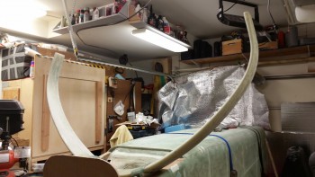
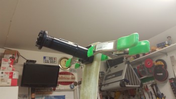
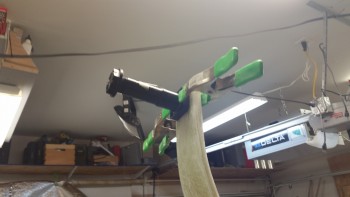
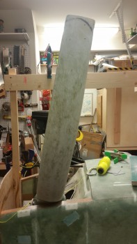
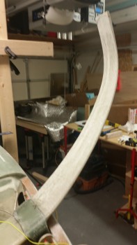
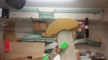
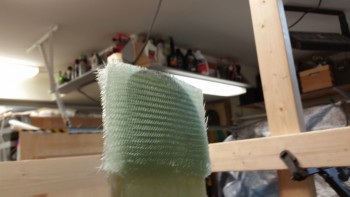
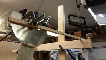
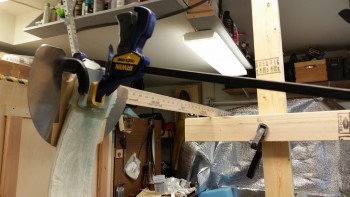
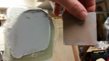
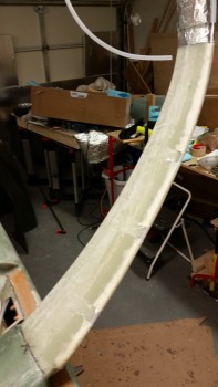
1 July 2012 — Today I pulled out the Main Landing Gear Bow that I received from Mike & Larry at Feather Lite (who apparently thought they would provide me an old-world European spelling of my name: “Wayde” vs the clearly Americanized version: “Wade” since I was on my way to Germany when they shipped it). I inspected the bow for any major dings or damage, and I cleared it with a clean bill of health. Since it looks so much like a regular bow (read: Robin Hood), I had to take a pic of it being used as such…. I know! I’m quite the card! Yuk-yuk…..

I took the bow out to the front of the house, threw it on my handy foldout table and commenced to sand it with my 32-grit sanding block. It doesn’t seem like this is much of a notable event, but this was not really a “small” or “lesser” task per se. One line in the plans to the effect of, “Oh, yeah, just sand it a little until dull” ends up costing you almost nearly an hour and a half of your life… sanding away! With itchy S-glass no less! And on an unusually warm German day, and of course wearing a respirator. No worries now though because this step is done!
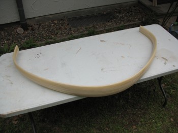
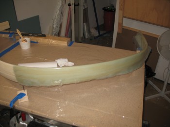
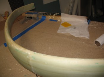
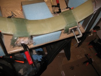
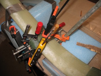
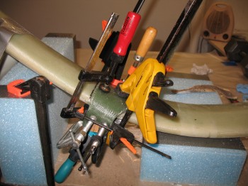
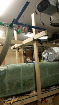
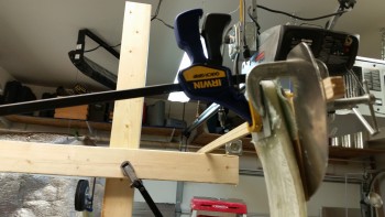
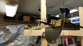
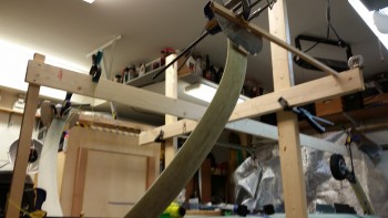
I vacuumed the gear after sanding and ensured it was fiberglass dust free. I then went to my downstairs shop and prepped it for glassing the main gear bow. I used 3″ drywall screws & 5-min epoxy to mount the gear onto the table.
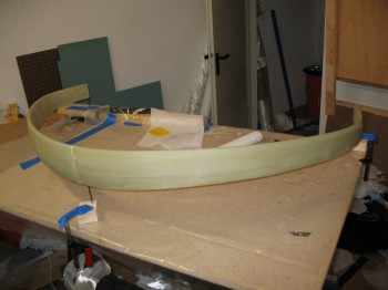
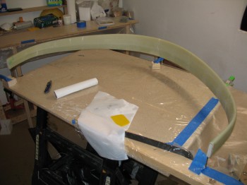
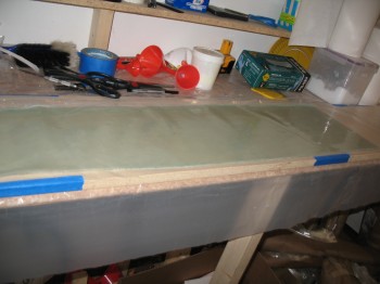
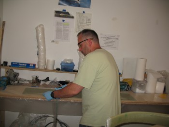
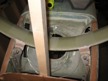
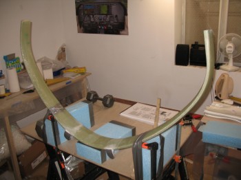
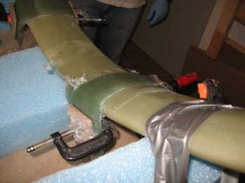
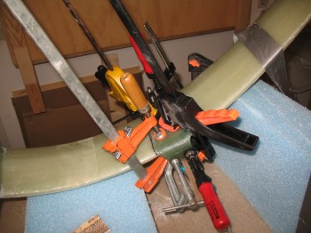
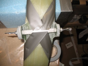
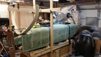
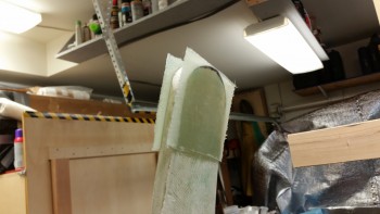
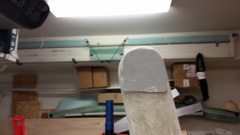
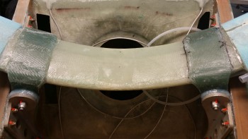
I laid up the first half of the gear layup, which has 4 alternating plies of UNI wrapped around the trailing edge of the gear and meeting close together (but not overlapping!) at the leading edge. After this first layup is complete there will be 4 plies on each side with 2 plies in one 30-40°diagonal orientation and the other 2 plies going in the opposite 30-40° orientation, so it merely creates a cross-hatch that grips the gear and provides it support when it flexes (kind of like sticking your fingers into those old style mesh curlers and then trying to remove your finger). I tackled the Right side first and then the Left, using a pre-preg method of course to ensure all the excess epoxy was squeegeed out.
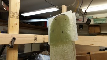
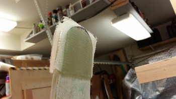
 After I got all the glass laid up on both the Left & Right sides, I peel plied the entire gear bow since it would be nearly completely covered with the next layers of UNI in the 4-ply configuration.
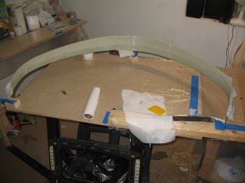
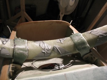
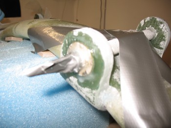
Later that evening, after the initial main gear layups cured, I pulled the peel ply and razor cut any offending glass around the leading edge.
I removed the gear from its 3-screw perch and cleaned up all the peel ply boogers.
•••
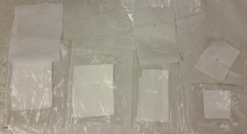
8 July 2012 — I prepped the plastic and peel ply for the second and final round pre-preg kits for glassing the main gear.
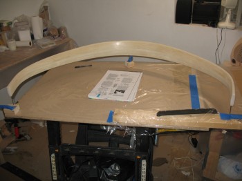
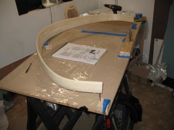
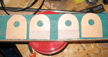
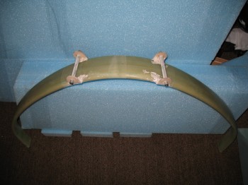
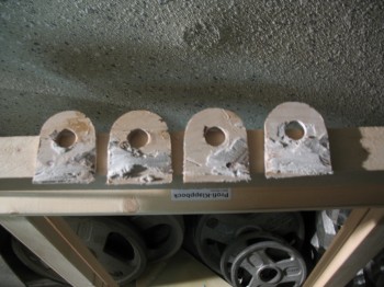
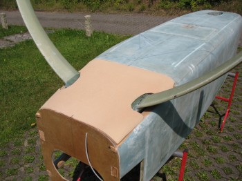
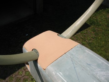
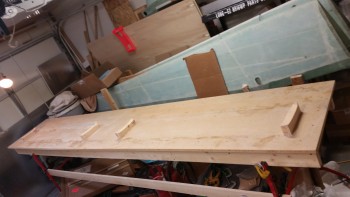
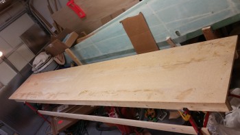
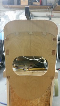
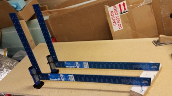
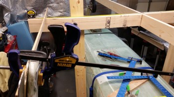
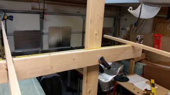
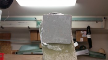
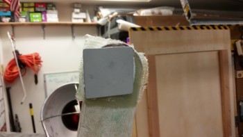
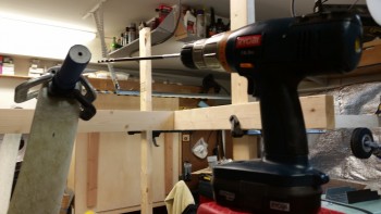
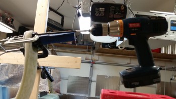
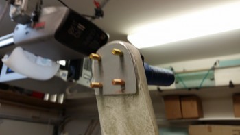
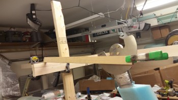
12 July 2012 — I spent about 2-1/2 hours at the wood shop on Ramstein today. Not nearly as bad as last time… I cut 4 each Main Landing Gear Mount jigs with 5/8″ holes and tapered edges. These will be used to temporarily “mount” the gear to the fuselage gear mounts with bondo and then also serve as the form to create the gear tabs that will eventually hold the gear to the fuselage.
After I finished messing about with the landing brake & wing jigs for a good portion of the day, I turned my attention back to the main landing gear. I spent over an hour and half sanding and prepping it for it’s final glassing.
•••
15 July 2012 — I finished sanding the main landing gear bow in preparation for glassing the last of UNI layups on the gear legs.
 I set up the downstairs shop to glass the landing gear: I cut the plastic for the UNI pre-preg set-ups and 5-min epoxied the gear to the 3-drywall screws.
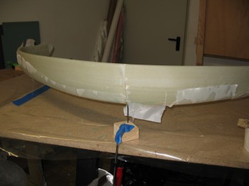
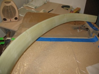
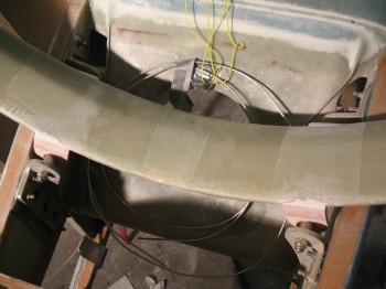
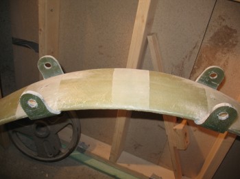
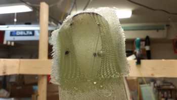
I then laid up the final sets of UNI.
When all was finished, I had laid up 4 alternating layers on both the left and right sides of the gear bow, wrapping around the leading edge and coming together on the trailing edge. Remember, each of the 4 layers of UNI alternate 30-40°, with two layers going in one direction and the other two layers going in the other direction to create a cross-hatch.
•••
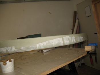
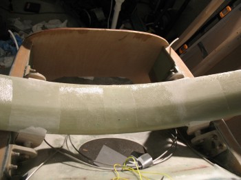
15 July 2012 — I took the gear off of the jig and removed all the peel ply from the gear. I then tore the jig down.
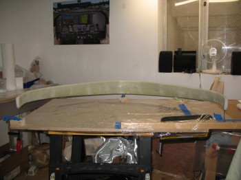
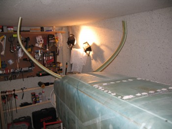
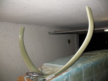
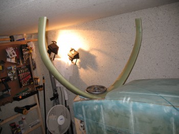
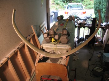
Well, with the main glassing done on the gear I had to see how the gear looked mounted. So I took the gear out to the shop and spent a fair amount of time messing about and mocking it up.
•••
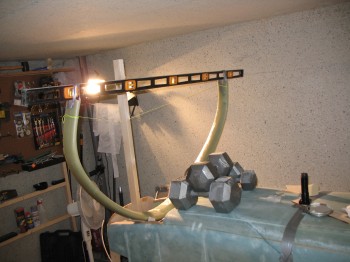
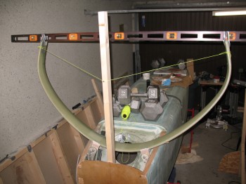
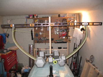
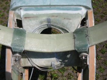
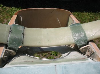
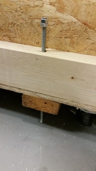
20 July 2012 — Today I turned my focus back to the main gear. I situated the fuselage back inverted and placed it on red stands. I leveled the fuselage longitudinally & laterally using weights to hold it in place. I then ensured the firewall was leveled vertically & clamped a 2×4 to it. (I had previously marked the 5/8″ OD steel gear mounting tubes (LMGAT) 0.65″ from each edge, put wood jig tabs in place, and remounted them onto the fuselage-side main gear extrusions). I put the gear in place and used an adjustable string setup to keep it upright and at the right distance from the firewall. I taped a 6′ long carpenters level to the bottom of the each gear leg, centered front-to-back so as to minimize any error. I set the gear with a 3/16″ gap between the top of the gear arch and the bottom of the fuselage longerons.
 I then set the axles’ centerline at F.S. 111.1 (stock plans is F.S. 110.5, but because I’ll be mounting a heavier IO-320 engine and some discrepancies I see in the plans, I’ll be moving the axle positions back about 1/2″ . . . [Ed. See my buddy Marco’s in-depth discussion on this at longezproject.blogspot.com… he explains it all nicely])
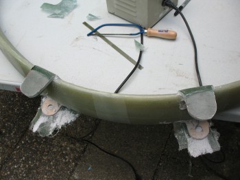
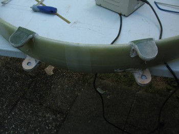
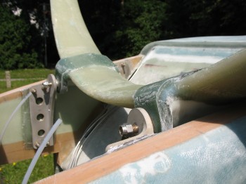
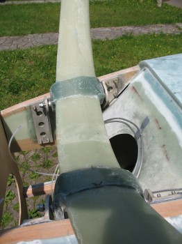
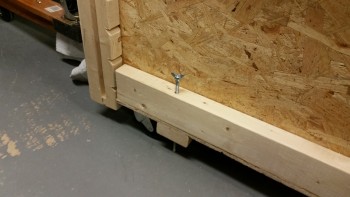
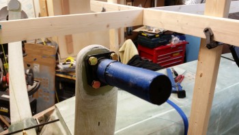
 After spending an hour or so ensuring that everything was lined up, straight, square… and that the measurements were as spot-on as possible, I bondo’d the wood jigs (that were pre-installed on the fuselage) to the main gear bow.
After the bondo cured for a bit, I trimmed the excess off & cleaned it up, and then left it alone to dry overnight.
•••
21 July 2012 — Now that the bondo–between the wood main gear jigs and the main gear–is completely cured, I final sanded it along with the glass on the gear in between the tabs.
I removed the gear bolts and removed the gear bow from the fuselage.
 I then went on a foraging mission for materials at Praktiker & Toom (German DIY stores).
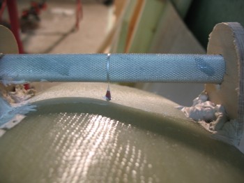
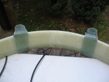
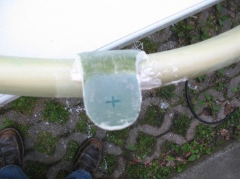
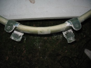
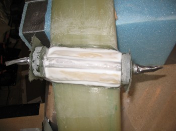
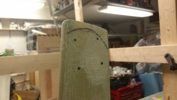
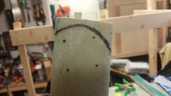
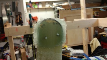
Upon returning from a successful buying venture, I marked the center of the steel gear tubes on top of the main gear & glued on two (2) small marker tabs (and marked the CL on the gear bow with a Sharpie… just in case).
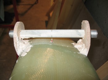
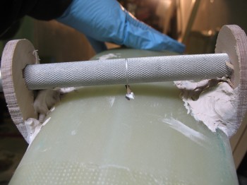


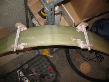
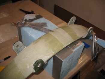
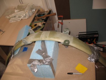
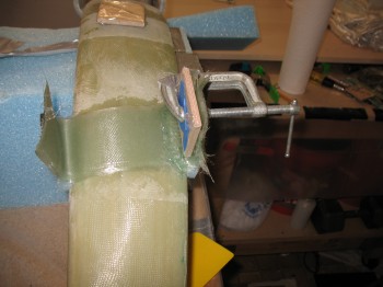
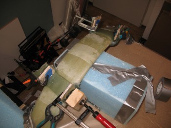
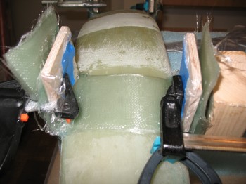
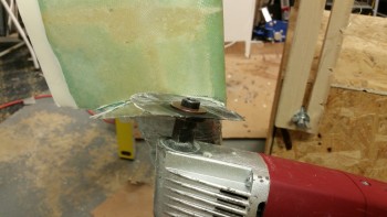
I prepped the workbench in the downstairs shop with spare wing foam pieces that I secured to the table, and then got the epoxy and glass ready (the glass that Gina had spent about 2-1/2 hours cutting…Hoo-ah! It’s awesome having help!). I took the main gear bow down to the prepped workbench and secured it to the foam/table.
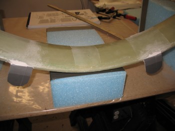
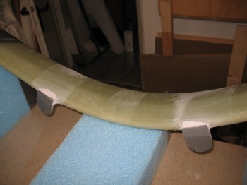
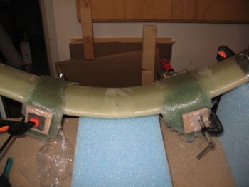
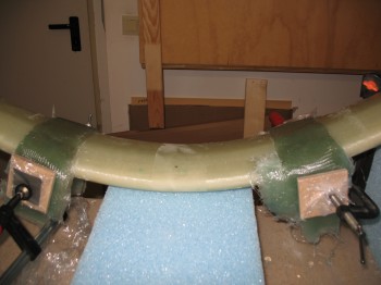
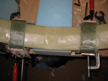
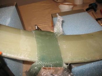
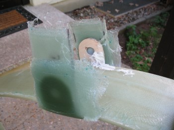
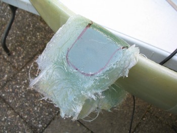
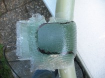
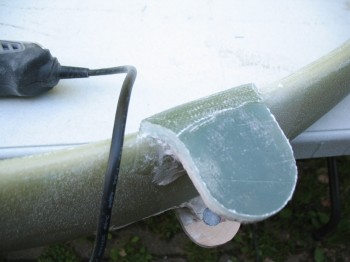
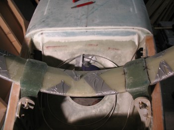
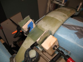
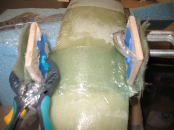
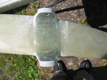
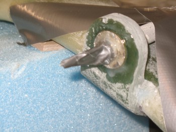
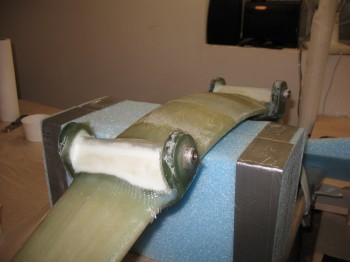
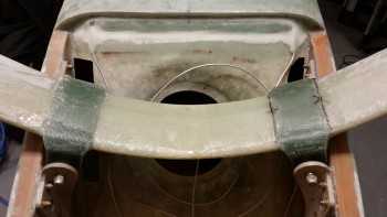
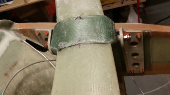
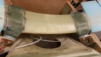
I then glassed 2-1/2″ x 12″ 18-ply UNI strips onto the bottom of the gear on each side. These long UNI strips start & cover the tab on one side, then get laid across the gear strut and end by covering the other tab. Analogous to a UNI “band” or “strap” across the bottom of the gear bow both on the left and right side. Once the 18-plies of UNI are in place, then on each tab, placed over the now pre-existing UNI band, an 18 plies of 2-1/2″ x 2-1/2″ BID squares are glassed onto each tab (only covering where the gray duct tape was applied). So, total glass each side: 18-plies of UNI (side-to-side strap) + 18 + 18 = 36 plies BID (tabs only). I then clamped 2-1/2″ x 2-1/2″ wood pieces covered in saran wrap (so they wouldn’t stick to the layup) over the outside plies of BID with just enough pressure to squeeze out any excess epoxy and to form a nice smooth/straight outer surface.
After a break, I glassed the Right front and Left rear console with 1-ply of BID and peel plied.
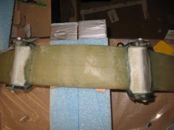
I also went back to the gear–with the layups being a little gummy but starting to harden–and knife trimmed the gross excess of glass (it looked crazy but it’s structurally correct… promise!)
•••
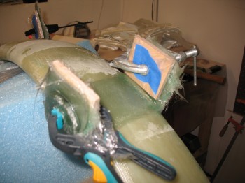
22 July 2012 — After I finished for the day with the consoles, I removed the clamped wood blocks and removed the main landing gear out of its mount.
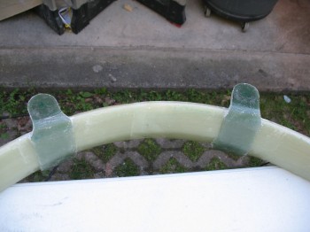
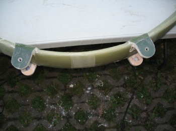
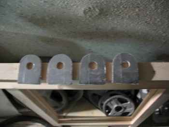
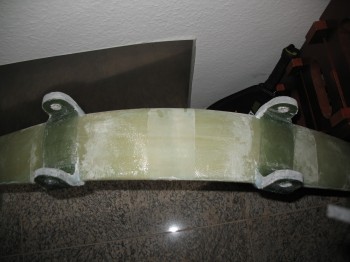
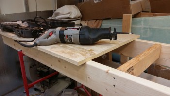
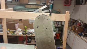
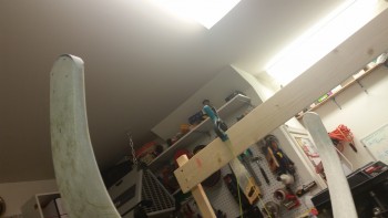
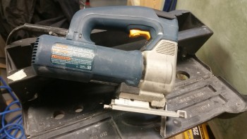
I then took the main gear outside & put in on the folding table (my portable workbench). At first, I started to trim the excess cured glass by using a coping saw, but that didn’t last very long. I quickly switched to something a bit more electro-mechanical, pulling out the Bosch saber saw! It worked great (read: “fast”) and I trimmed the excess glass on the tabs down to within a respectable 0.1″ of the wood templates.
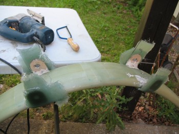

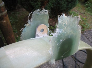
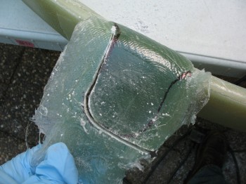
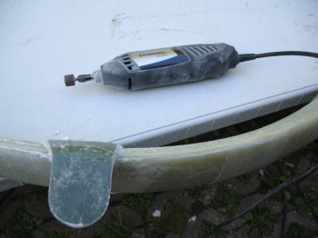
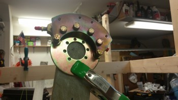
I Dremelled the gear-tab to gear-leg junctions to get a smooth, round, flowing edge for all the tabs. With the Dremel I was also able to clean up & smooth out the saber saw marks around the outer edge of the tabs.
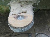
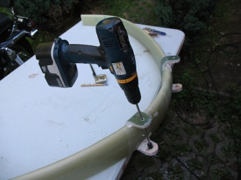
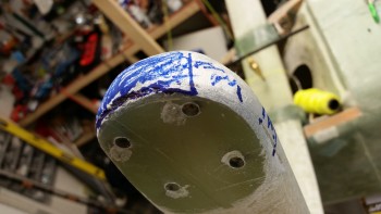
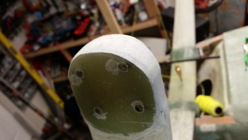
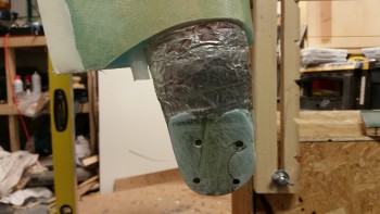
I marked the center of the holes & drilled a 1/8″ pilot hole to check that I was centered in the hole (the 5/8″ hole of the wood jig).
Once I was centered, I drilled 3/8″ pilot holes & then used the 5/8″ arbor bit to drill the main landing gear holes… it worked very well!
I tried to insert the steel LMGA tubes into the holes, but they wouldn’t go in. I used my round Perma-Grit tools to bore out the holes a little wider, going very slowly and removing just a very little bit at a time. It was a fair amount of work & took about an hour to do, but I definitely wanted to ensure the fit was tight and the holes weren’t bored out too wide. Also, while boring out the holes I realized that the final fit should be without the wood jigs attached. So I popped the wood jigs off, finished boring the holes and then spent about another hour digging, sanding, grinding, clawing and scratching out the dried (or should I say cemented!) bondo.
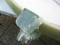
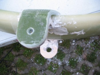
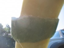
Well, I think I’ve shared my personal philosophy on building an airplane. I’ve said over & over again that building any airplane is simply having the perseverance during the build to repeatedly fix the things you royally screw up. And this my friends, was one of those times. As I was sanding the tabs, I noticed a dark line near the inside of the tab. I sanded it down a little and messed around with it, but it was still there. I then realized it was probably plastic from the peel ply layers. I confirmed this by sticking in a razor blade and digging out some plastic! That’s when I deftly thought: if it was on this side…?! Yep, there it was on the tab opposite the one I was working on. I realized that with it being on both sides it wasn’t simply an anomaly, it was something serious & bad . . . I took the gear out to the garage and marked the edges of the tab glass and put a couple of X’s on each side for alignment purposes. I then put some towels down on the floor, grabbed a rubber mallet and hit it a few times. At first it didn’t seemed to do anything and all appeared solid, but I wasn’t overly convinced so I gave it a couple more good whacks and off it popped. Smooth and shiny on the inside.
Well, I made a few phone calls & talked it through. After a bit of discussion, I finally decided to sand each side down and flox it back on. Besides bouncing it off some other bubbas, a few key things helped me in that decision. First, flox is some tough stuff & it’s structural. Second, the effort that it took me to knock the tab glass off with only a layer of plastic between the plies was significant, serving as a testament to just how much grip strength epoxy has in general–that a layer of plastic would hold so well. And third, the configuration of the landing gear tabs has the steel LMGA tube floxed across and through each side of the tab holes, then into all of the plies on the piece that was knocked off–with the remaining plies still left on the gear–and the soon-to-be inner plies that I would glass in. Thus, I decided I would proceed with the flox repair.
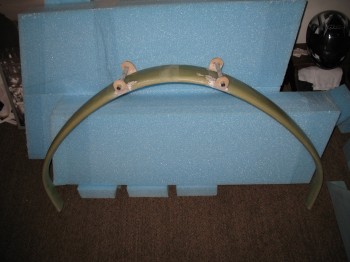
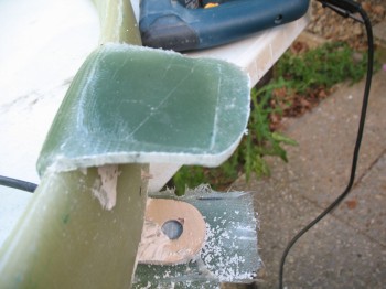
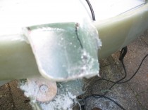
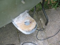
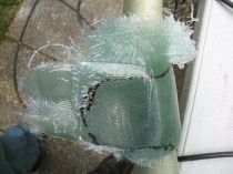
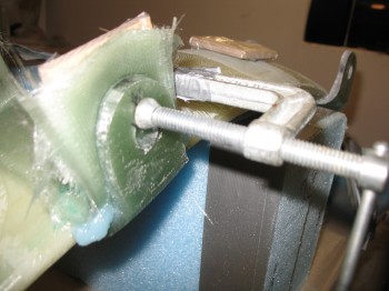
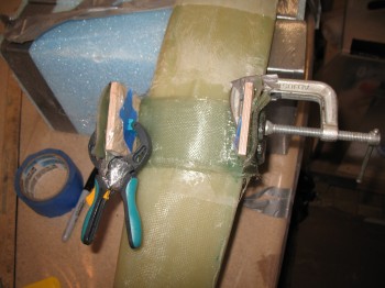
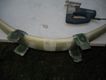
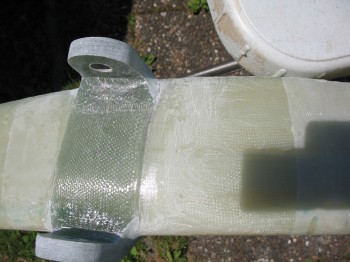
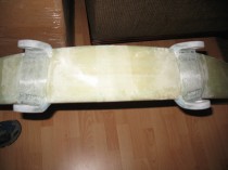
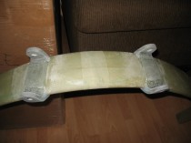
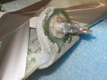
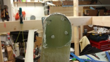
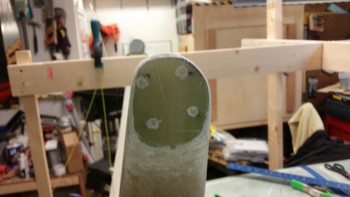
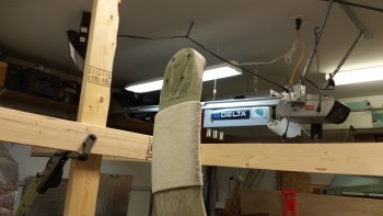
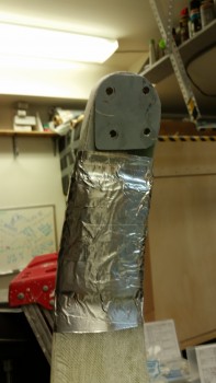
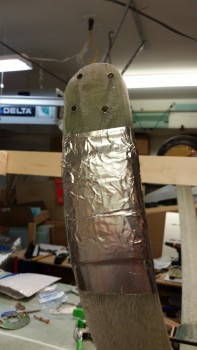
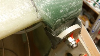
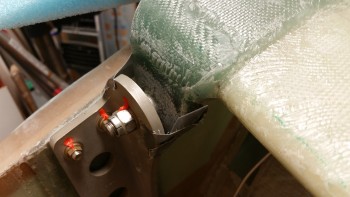
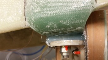
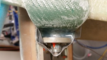
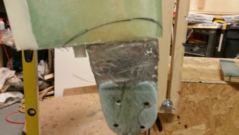
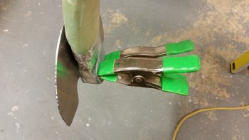
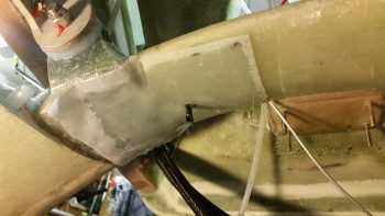
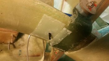
Unfortunately, the only pictures I have were after all that took place, since I was in emergency response mode and not concerned about documenting anything until afterwards. You can see in the pics below that the flox has just been applied and the gear is back in the workbench mount with a plethora of clamps holding it tightly back into place.
I checked it out before I went to bed. The clamps had held it in exactly the same spot, with no slipping or movement, so I called it a night.
•••
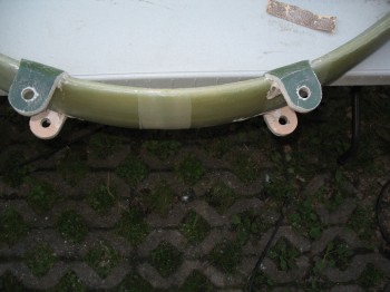
23 July 2012 — I removed the clamps from the flox gear repair & did a mock install on the fuselage… Success!
•••
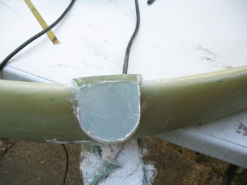
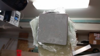
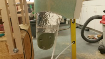
24 July 2012 — I laid up the inside glass on both the main gear tabs. I also glassed a 3-ply BID layup on the outside of one of the tabs that seemed a bit thin (the ply-count was good, but the compression from the clamp appeared to have pushed the glass a little down towards the base of the tab, leaving the top a little thinner as compared to the other 3 tabs).
After a couple of hours had passed I knife trimmed the glass & cleaned up the edges… the layups looked good!
•••
25 July 2012 — I removed the blocks and the clamps from the gear tabs. Layups looked good. I cut & sanded the inside gear tab layups to match the outside gear tabs.
I then redrilled the 5/8″ holes for the final time.
•••
26 July 2012 — I hand sanded the landing gear tabs & used the Perma-Grit tools to create a beveled edge at the tab-to-gear bow junction.

I used the small round Perma-Grit to again re-bore & open the land gear tube holes.
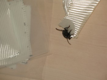
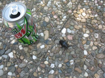
I once again had a friendly visitor stop by… he hung around for a little while and then went on his way (with some assistance!).
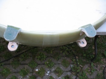
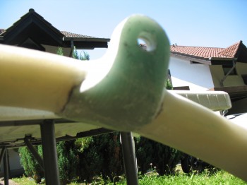
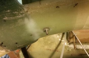
I mounted the steel landing gear tubes into place with flox, then immediately floxed & glassed large AN washers onto the outside of the tabs with 2-ply BID layups.
I then carved foam wedges as “ramps” for the landing gear tubes & micro’d them into place. I then covered the micro’d ramps with 2-ply BID layups. These ramps allow for glass to hold the steel tubes in place, but still have a smooth transition to the base of the landing gear bow.
In between the drying stages above, I knife edged all the new tab edges.
•••
27 July 2012 — I final knife cut & sanded out the main landing gear tabs. Then I took the gear outside & mounted it to the fuselage… it fit! (Whew!)
I then measured the respective gear legs to the “nose” centerline mark. One side was 0.2″ closer to the CL mark than the other … oh well, I’ll mitigate that when I mount the axles.
I tightened up the gear bolts & flipped the fuselage over so it was sitting on the gear. It looked good!
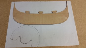
And finally, before I put the fuselage away in storage, I played around with some urethane foam & cut/shaped a hellhole cover… kind of a pain. But good experience.
•••
16 May 2012 — I researched & ordered my AN brake line fittings.
•••
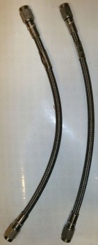
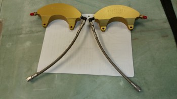
21 December 2015 — I received my 3/16″ Statoflex 124 brake line hose assemblies today and they’re exactly what I wanted!
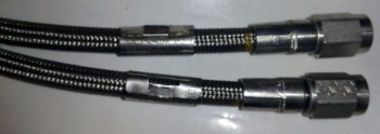
Here are a couple more shots.
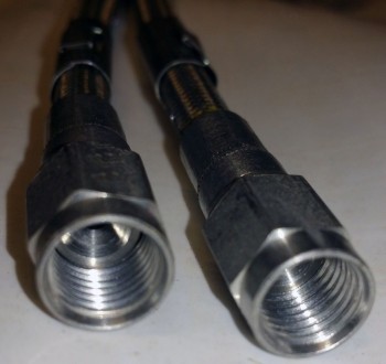
If Bob Nuckolls is the King of Electrons, then I’d say Tony Bingelis was the King of Engines, and almost all things mechanically related to aircraft. Now, just as I have on occasion angered the gods, mainly Burt, (as if he actually knows what I’m doing… ha!) by violating his edicts with a few mods here & there, so too did I violate one of Tony’s. Tony states to always go with new hoses and not NOS (New Old Stock), but given the history of these hoses, the care in which they were stored (detailed), the price compared to new, and the fact that they were EXACTLY what I was looking for dimensions & fittings wise, I just couldn’t pass them up.
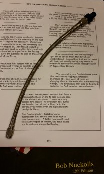
Below is a shot confirming that the new hoses work with the AN3 fittings I have on hand. Sweet!
•••
23 January 2016 — Today I didn’t make it to the shop to do any actual physical work.
I did however spend a good 7 hours planning & sequencing out the remainder of my Long-EZ build. Specifically, I spent the majority of time creating my build plan & task list for installing the main gear, axles, wheel & brake assemblies, tubes & tires, dealing with toe-in, glassing the gear fairing, identifying required tools, hardware & materials, and the eventual install of the wheel pants, as well as well as a myriad of other associated main gear related tasks.
To finalize this plan I reviewed the plans Chapter 9. Canard Pusher plans changes, Matco wheel/brake install manual, Eureka CNC gear fairing install instructions, CSA articles, Sam James’ wheel pants install manual, builders’ websites, forums, and my compilation of main gear related build notes over the years.
Since I now have the lion’s share (about 90%) of the specific main gear install plan in hand, I can go back to finishing up nose & elevator stuff as I start transitioning into focusing on the main gear final install.
•••
28 January 2016 — Today was all about getting the shop reorganized for the main gear install.
I started by clearing off the top of the canard building table.
And then removed the canard supports. I also thoroughly cleaned the work bench top by removing all the epoxy puddles, flox & micro residue, etc.
I then dismantled the canard work bench.
But not before cutting off the last third to make a smaller work bench top. This should help my back when I’m working with my portable workbench tables that are just a tad too low to be working over them for hours & hours on end.
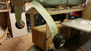
I then spent a few hours cleaning and organizing the shop to get to my final result: getting the fuselage flipped around in order to work on the aft end. I have to say that I was really pleased with my fuselage dolly here in that it made it really EZ to get the fuselage flipped around. Even though the 4 wheels aren’t the highest grade and are probably just a little overtaxed, they do ok on making the fuselage dolly a really useful mobile work platform.
•••
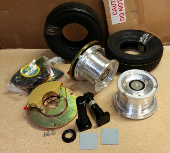
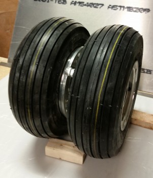
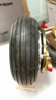
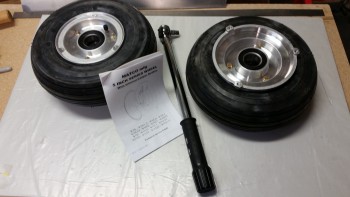
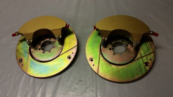
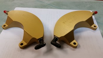
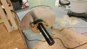
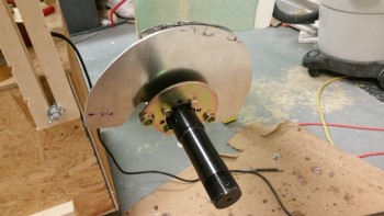
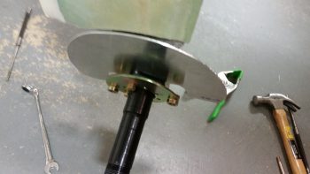
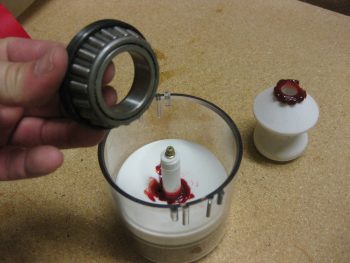
31 January 2016 — Today I pulled out the Matco W50LT wheel & brake assemblies and Lamb tires to inventory all the parts and check them to ensure they were in good working order. Some of the water soluble packing peanuts had adhered themselves to some of the wheel & brake assembly surfaces, so I spent about 15 minutes cleaning the residue off.
I then spent a good 15 minutes assessing the spacing of the engine mount on the firewall to see how it aligned with the longerons (not shown).
•••
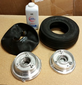
1 February 2016 — Today I started on installing the tires & tubes to the Matco main gear wheels.
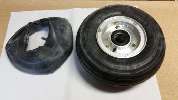
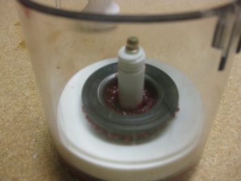
And here’s the end result. One wheel with the tire & tube installed, and yet another casualty! On try #1 I followed Matco’s directions by adding about 10 PSI of air into the tube when it was installed in the wheel before bolting both halves of the wheel assembly back together. This made the process nearly impossible, even with clamping both halves together.
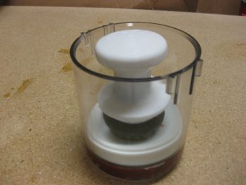
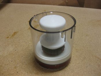
So, round #2 I followed the sage advice of Frank Sinatra and, “Did it my way!” by not adding any air, clamping the tire down to ensure that none of the tube would get pinched, then bolted it together and filled ‘er up to about 50 PSI (70 PSI is max on this tire/tube combo). Voila! It worked!
Note that each time I did use talcum/baby powder to reduce the friction of tube going into tire.
Also, I will order a couple more tubes from ACS later this evening.
After messing around with tube & tires, I spent a couple of hours making a few phone calls before returning back down to the shop.
•••
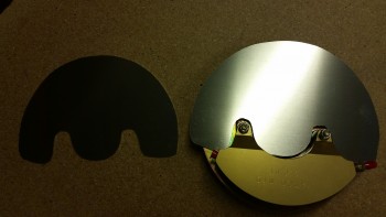
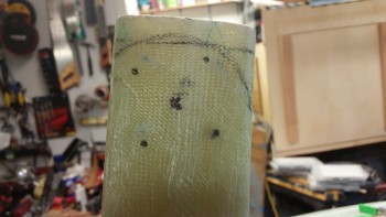
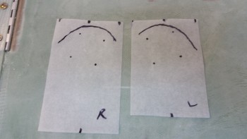
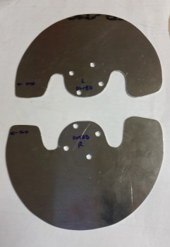
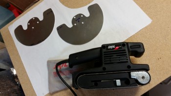
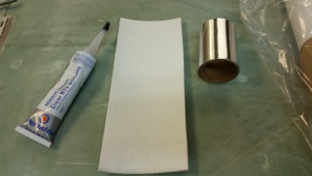
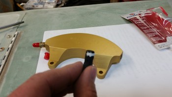
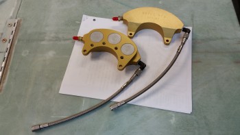
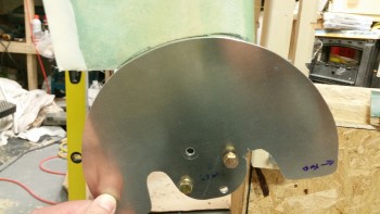
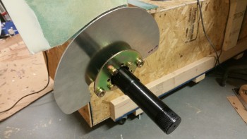
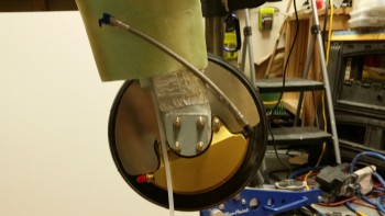
2 February 2016 — In the pic below you can see the paper template that I will finish tweaking in order to cut out the 0.09″ thick 6061 aluminum heat shields for the lower gear legs (as per CPs). I’m using 6061 vs 2024 since it is more corrosion resistant, and that will be a definite benefit in the lower gear & wheel well environment.
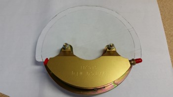
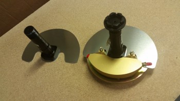
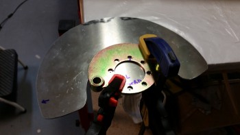
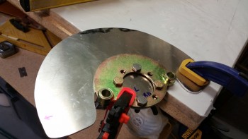
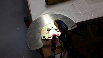
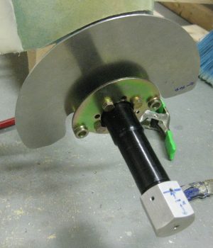
Here’s the lower gear heat shield test fitted onto the wheel brake assembly.
•••
3 February 2016 — I got a late start today so I didn’t get nearly as much done as I wanted to tonight.
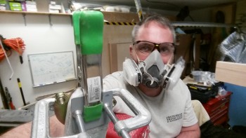
I figured at some point I should add a selfie for the FAA, so here it is!
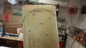
I then traced the gear leg brake disk heat shield template onto the 0.09″ thick 6061 Aluminum plate for cutting. Again, I’m using 6061 Aluminum as a heat shield since it’s much more corrosive resistant than 2024 aluminum, and in this application, strength is not really required.
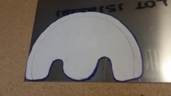
I then cut out the heat shields using my jig saw.
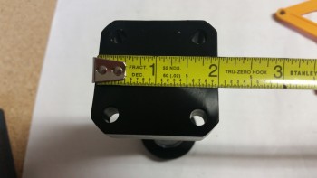
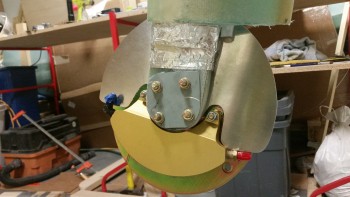
I then test fitted the axle mounting flanges on the heat shields. So far, so good!
I pulled the gear out tonight to clean it up & then mount it, but then I realized that I needed to sand the entire gear bow in preparation for attaching & glassing the gear fairing to it. It was too late to undertake a big sanding job, so I’ll do it later.
•••
5 February 2016 — Due to prepping for a Superbowl Party that I’ll be having at the house on Sunday, I didn’t get any work done on the plane yesterday.
Today I mounted the extended firewall to the aft fuselage early on in the day.
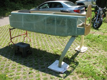
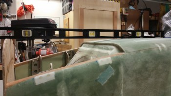
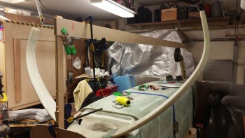
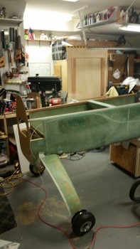
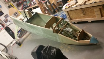
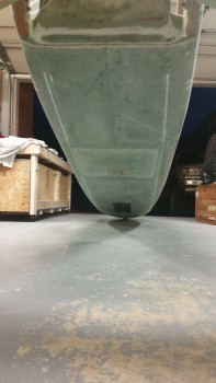
Here’s a shot showing approximately what the new profile of the aft fuselage will be when the plane is finished. Of course this is upside down, but clearly the width & bulk of the fuselage will be extended aft to create more of a “boat” shape vs. the traditional swoop of the old P-51 style inlet. In short, my Long-EZ will have the same profile as one that has a NACA scoop intake.
That being said, I will have a 3″ round air scoop, somewhat like James Redmon has on his Berkut 13, that will run from aft of the landing brake and slowly meld into the bottom hell hole area so that it should (still in design phase) dive aft into the firewall and flow into the lower cowling skin. Thus, I guess my EZ will look a tad different than all the NACA-scooped EZs.
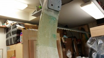
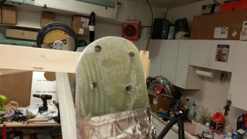
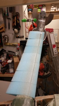
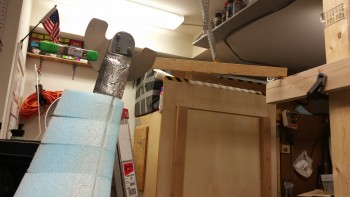
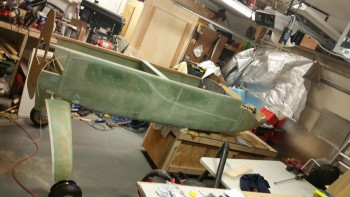
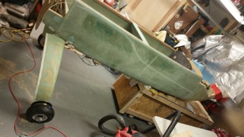
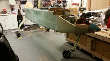
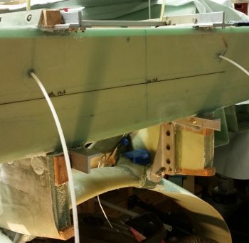
I had pulled the main landing gear bow out a few days ago, but just this evening –with the help of my buddy Greg– I sanded down the gear legs for the eventual adding of the gear fairings, and then (re)mounted the main landing gear bow back onto the fuselage.
Although there was the usual fight to get the bolts in, I was pleased that in the end, after a few years of the gear being off & redoing the washers on the mount extrusions, that the gear fit back into the mounts with only a little bit of banging with the hammer required.
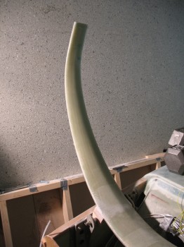
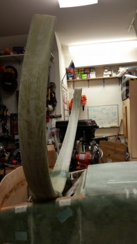
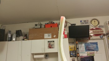
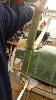
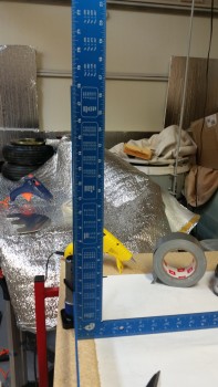
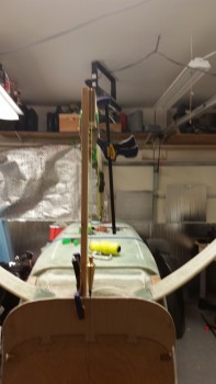
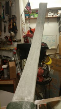
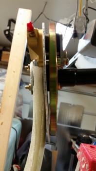
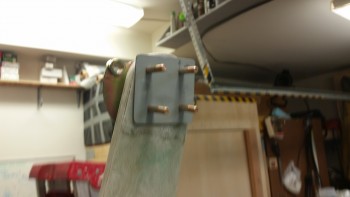
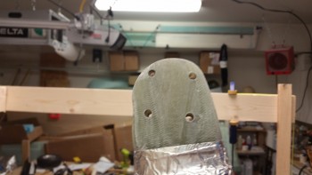
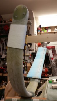
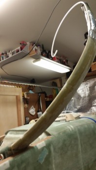
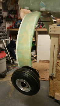
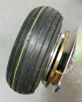
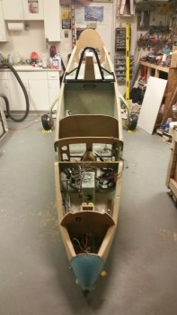
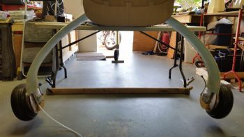
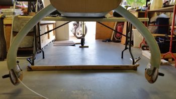
Here’s a vertical shot of the main gear legs.
•••
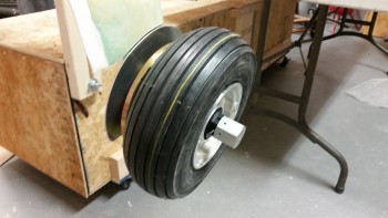
6 February 2016 — Today I got the tire & tube mounted on the other wheel. Since I was trying to get at least this one thing completed for the build before I headed out to dinner, I didn’t balance the yellow stripe on the wheels, so I guess that will somehow either make the plane fly crooked or the wheels not in synch! Although I try not to sweat the small stuff or be too anal as to add unneeded time to the build, had I noted the position of the yellow stripe, I would have mounted the tires symmetrically.
Just like the previous wheel I inflated the newly mounted tire to 50 PSI. I’ll watch the tire pressures for about a week and make sure they sustain 50 PSI, and when I’m sure that they’re are no leaks, I’ll inflate both tires to 70 PSI.
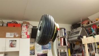
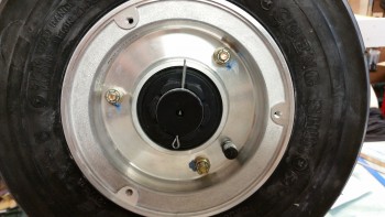
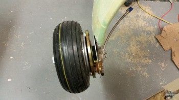
Here they are, my officially mounted tires! Again, I’m running Lamb 11 x 4.00-5 tires on Matco W50LT wheels.
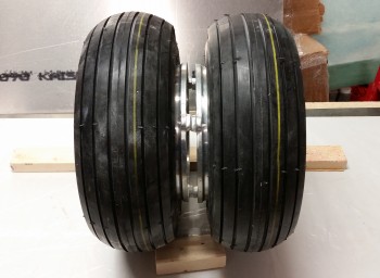
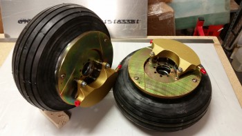
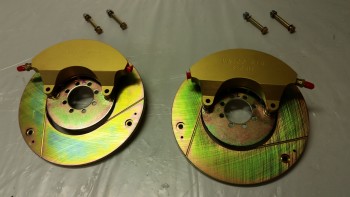
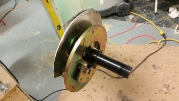
I then added the brake assemblies to the wheels for these pics. I’ll still have to torque the bolts to the appropriate specs as I do final mounts on each of the wheel components, so the only actual torque job on my immediate list is the main wheel halves.
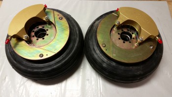
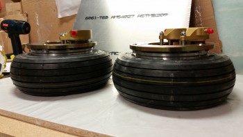
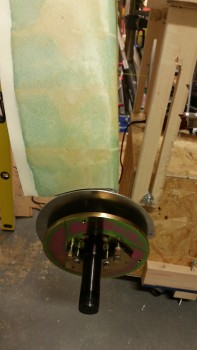
Finally, here’s a couple shots showing the width & depth of the brake assembly mounted to the inboard of each wheel.
•••
10 February 2016 — I started off today doing some final research on the threaded axle caps (p/n VA-106) from VANs Aircraft that makes installing Sam James’ wheel pants to Matco wheel assemblies doable without having to drill & tap the end of the Matco axles. After speaking with the guys at VANs & confirming that I had the correct part, I ordered a set.
Down in the shop I started by torquing the main gear mounting bolts (AN6-80A) to 275 in/lb as outlined in CP 46. For added strength I also added a couple drops of red Locktite to each bolt.
I then spent over an hour leveling the fuselage and ensuring it was square & plumb. As I started this process, the fuselage was really off as I tried to level it from side to side. I finally did some investigating and looked inside the overturned fuselage. It was then that I realized that the fuselage had slipped off on one side of the 2×6 sized board that I had it resting upon. Once I corrected that little SNAFU, it made the process of leveling the fuselage much easier.
In addition to shimmying the fuselage to get it level, I also used the threaded rod leveling feet that I had mounted in each corner of the fuselage dolly for the first time. They’re a bit narrow in diameter, but they definitely help.
Here’s another shot.
Once I ensured that the fuselage was level, I measured the distance between the main gear legs and points on the forward gear strut & the forward nose centerline.
I took 3 measurements from each gear leg, then shot 6 measurements to each leg from 2 different forward points on the nose & nose gear leg, respectively. In the end, I had 9 measurements for each leg, 3 for each specific point. I averaged each set of 3 numbers, determined the delta between the left & right gear for each set of numbers, then averaged those final deltas to get a final averaged aggregate delta.
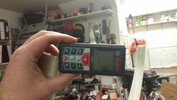
When I originally mounted the gear I had determined that one side of the main gear was a 1/4″ farther aft than the other. However, I was using a standard measuring tape when I originally mounted the gear. When I used the laser measuring device this time, my delta between the left & right side gear legs came out to only 0.087″, which is fantastic as far as I’m concerned.
After I determined that the gear legs were a close match in both elevation (I checked when I leveled the fuselage by placing a long level across the gear leg bottom edges) and forward & aft, I then determined the WL of the center of the axles.
Since the longerons sit at WL 23.0, and the axle centers are at WL -22.0, then it stands to reason that by simply measuring 45 inches from the top of the longerons to the lower gear legs that I could determine the axle mounting location. Now, there does need to be an adjustment as Marco points out on his blog since LPC#45 moves the 3/8″ bolt holes on the main landing gear mount extrusions up 0.4″, which isn’t accounted for in the WL -22.0 dimension. Thus, this moving the bolt holes up 0.4″ makes the new height of the gear at WL -21.6.
So when I measured the height of the center of the gear axle, I subtracted the 0.4″ to make the dimension 44.6″ up from the longeron (when the fuselage is upside down) to the center of the gear axle location.
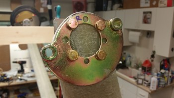
Here’s a shot of the approximate center point of the axle at 44.6″ below the longeron (at WL -21.6).
When I marked the left side gear leg, the 44.6″ mark was 1.3″ away from the end of the center of the gear leg. I really wanted another 0.2″ inches, and then lo & behold I realized that the other side of the level pressed against the longerons had slipped a bit. Once I wedged the level back tight against the longerons, I remeasured the left side and was able to reclaim my 0.2″ so that the 44.6″ mark was at 1.5″ above the bottom of the gear leg (below with the gear upside down).

I wanted the 1.5″ gap between the bottom of the gear leg and the center point of the axle since the axle bases, as shown below, are 2″ square. Since a half inch provides room to remove some of the lower gear leg for clearance for the Matco brake calipers.
Here’s the 1/2″ mark on the left gear leg.
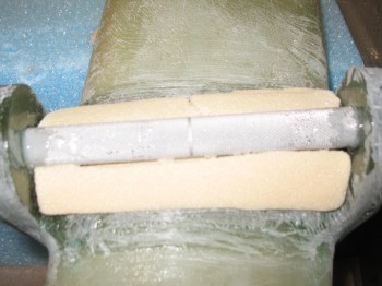
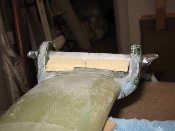
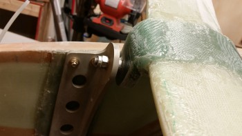
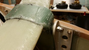
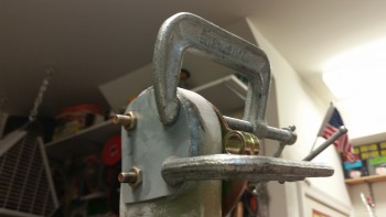
Below are the Matco axles clamped into place to test the fit, both on the left & right gear leg.
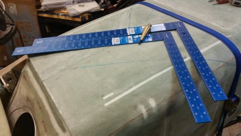
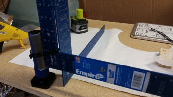
In preparation for mounting the axles to the gear legs, I made a run to Home Depot today and picked up some aluminum squares and a plumb bob, as you can see in the pic below.
I then went back to work on the main gear wheels. The first thing I needed to do was torque all the bolts to ~99 in/lbs (8.5 ft/lbs).
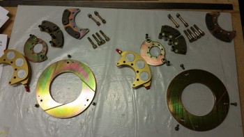
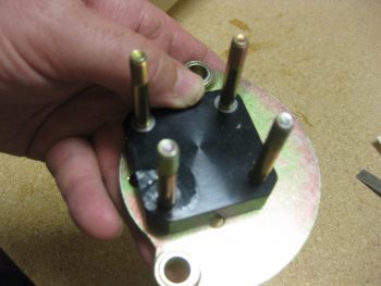
I then disassembled the brake assemblies in order to isolate the brake disk mounting flange that I will need to mount the wheel assemblies onto the axles.
I first removed the 2 longer bolts from the outside edges of the calipers.
I then removed the 4 large diameter bolts in the center of the caliper assembly, and laid out all the parts as a sort of inventory & acquaintance of the parts, but specifically to ensure the brake pads looked ok & weren’t cracked (which happened to my buddy Marco).
•••
11 February 2016 — I started today by doing some more research and analysis on the steps to install the axles to the main gear legs. It’s interesting because just about every builder I know installed the axles and determined the toe-in angle close to the method described in the original plans, but to a builder they all did something significantly different than the way the plans detail the process.
Although I’m not casting doubt on the plans method entirely, I do want to optimize the process for installing the axles to the main gear & also in dialing in the toe-in angle, so some non-plans steps are most likely in order. Admittedly, since I haven’t finalized the final flow of how the axle install process, I’ll knock out all the prerequisite steps and let the process reveal itself (said while sitting in meditation position . . . ha!).
In the shop I started by spending about 45 minutes filing the edges of the heat shields to finalize their shape and remove any heinous, finger-shredding burrs (see heat shields below).
I then determined the position of the left axle on the gear strut that allowed for the optimized placement of the brake caliper to minimize the removal of the bottom gear strut material.
After setting the angle & position of the axle on the left side, I made up a template using tracing paper. I then transferred the mirrored image of the left side axle placement onto the right lower gear leg. Once I finalized and confirmed the placement of the axle on the right gear leg, I then made up a template for the right side as well.
These will be used IF I decide to follow the plans method which says to sand down the lower outboard gear leg to dial in the toe-in angle before trimming the gear leg or mounting the axle. Clearly if I sand the lower gear leg, all my markings that I just finalized will be wiped out. Thus, with my templates I can reapply my markings after shaping the gear legs for the toe-in.
Here’s the right side lower gear with both the axle placement and lower gear removal markings shown.
Once I finalized the positioning of the axle, I used the wheel mounting flange as a template to drill the 1/4″ mounting holes in the left heat shield.
Here’s the left heat shield mounting bolt holes drilled with the test fitting AN4 bolts installed.
And here’s the right heat shield mounting holes drilled.
A shot of both heat shields with the holes deburred & the sides filed smooth.
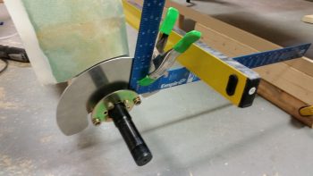
After finishing with the heat shields, I started work to attach the aluminum squares to the axles to determine wheel toe-in. I wrapped the axles with tape to protect them from any out of control glue gunk. I also used a zip tie to keep the square tight against the axle.
I then used the free square to ensure that the first square I was gluing to the axle was …. yep, square.
I then glued the second square to the other axle.
•••
12 February 2016 — I started out today by applying orange Torque Seal to all the gear mounting bolts in the hell hole.
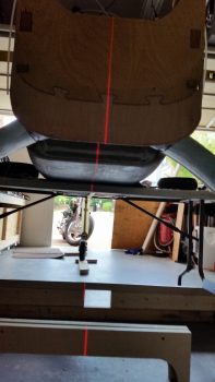
I then mounted a 1×2 vertically on the firewall, offset 3/8″ so that I could then mount a horizontal 3/4″ wide board down the CL of the fuselage. I originally was going to use my German aluminum long boards for the alignment board, but it wasn’t as straight as the 1×4 pine board I had on hand.
Here’s a shot of the 1×4 CL alignment board. As you can see, completing Chapter 13, the nose gear, allowed me to set the nose gear at just the right height & use it as a mount. Pretty darn handy!
I set & verified the CL alignment board with a plumb bob at a few spots along the length of the board.
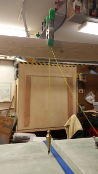
Here’s a shot of the installed CL alignment board.
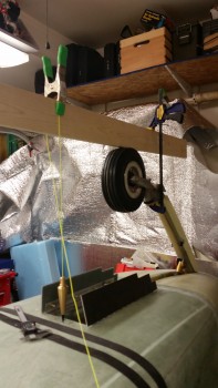
I then clamped my own version of the “Straight Tower of Pisa,” somewhat like my buddy Marco did.
A shot of the left axle clamped in place, with a square attached.to it.
Another selfie for the FAA, right before I started in on all the major sanding of the gear bow.
I sanded the left gear leg down to set the toe-in.
Then, when I started checking the toe-in on the right gear, my measurement at the gear strut came out right about 0.12″ farther outboard than the left side. I strung up my plumb bob over the center mark on the gear bow & confirmed that the gear was set about 0.12″ off center to the right. Not sure how this happened since I had it dialed in while in Germany, but it was definitely an issue that I felt I should deal with.
After some thought, I decided to simply add 6 plies of BID on the exterior side of the left gear to move the wheel out about 0.1″. Really, I don’t think being an 1/8″ off would cause any noticeable issues, but I want to keep the wheels difference from CL under 0.07″ or smaller.
After getting the initial toe-in set for the axles, I sanded down the entire gear legs for both the axle mounting BID gear pads, and the eventual installing of the gear fairing.
Here’s a shot of the right gear leg after final sanding.
I then double-checked the lower gear leg markings . . .
. . . and then initially trimmed the end of the gear legs.
Here’s another shot of the trimmed gear legs.
Here’s the specialized gear trimming tool . . . ok, it’s a jig saw!
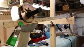
I then test fitted the wheel assembly onto the end of the gear leg.
Another shot of the wheel assembly test fit. I still have some lower gear glass to trim, but this is a good start.
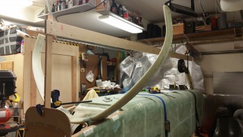
Here’s a wide angle shot of the whole axle install effort.
I cut the 3″x 3″ square BID plies for mounting the axles. I cut 2 sets of 3 plies of BID for the right side, and then 1 set of 3 plies and another set of 9 plies for the left side.
I then prepregged the BID pads in sets of 3 plies,
and wetted them out.
I then laid up the BID onto the lower gear legs.
Lower gear legs 3-plies BID (outboard right side)
Lower gear legs 3-plies BID (inboard right side)
Lower gear legs 9-plies BID (outboard left side)
Ok, I then let the epoxy cure for over an hour to set up to just tacky before mounting the axles to minimize the slipperiness & sloppiness of the wet BID. Well, it didn’t make any difference really.
To be honest, I’ve never been more pissed off during this build than this step right here. If ever I should have followed my buddy Marco’s lead & taken a page out of his book and pre-drilled the axle bolt mounting holes it was here. Trying to mount multiple components to a surface with multiple curves on BOTH sides with clamps is, to put it politely, stupid at best. Hats off to other builders that have done it, but as I said it was truly the most infuriating thing I’ve tried to do on this build. It also may be that the Matco axle base is narrower than the other brands, not sure, but it was about impossible (at least for me) to keep so many variables in check.
With the nearly cured glassed getting tweaked by the constant re-clamping of the axles, I eventually chucked them and simply used the face of the heat shields to determine toe-in. For any builders reading this, I would highly recommend this route. That combined with just laying up the BID one side of the gear leg at a time to minimize variables and slop.
I say this because after the sheer ass-pain with the left gear, then of course I spent well under 10 minutes on the right gear side mounting the heat shield and back axle plate.
As for the toe-in figures, my goal was to keep the difference between the 0″ measurement and the 24″ measurement between 0.1″ and 0.15″ to ensure that there is some toe-in, but not too much. I hate to say it, but this is one of those layups that I’m crossing my fingers and hoping on, since it looked good after I was done clamping it all together, and 10-15 minutes later… but it’s late, I’m turning it and who knows what will greet me in the morning.
•••
13 February 2016 — I thought I’d start off this post with a couple of pics showing my toe-in efforts from the top side looking down. In the top pic you’ll note the 2 blue aluminum squares, which, of course, I didn’t even end up using.
With the BID pads cured on each side of both lower gear legs, it was time to assess the damage. I popped the heat shield off each side, and the first item of note was that I was going to have to remove the epoxy nubs that resulted from some of the epoxy squeezing through some of the heat shield bolt holes. This wouldn’t have been an issue if my heat shields had stayed put and weren’t off from the marked bolt hole locations, since I would have simply drilled right through the nubs.
I decided to organize the pics in progression (vs. true chronological steps), at least initially, for each item. Thus, below you can see the transformation of the left side outboard lower gear leg as I sanded & shaped the 9-plies of BID. [NOTE: What appears to be bolt holes drilled into the face are not holes, just areas where I removed the “nubs” I mentioned above.]
Here’s the back axle plate on the inside left lower gear leg. The left side held decently, even though it was the side that gave me the most fits.
But the right lower gear leg was jacked up on both sides, although I didn’t realize the outboard side had any real issues until I went to mount the axle & heat shield later (more below). Basically, you can see the flat spot in the middle which looks like the pupil of a cat’s eye, with the unpressed BID to either side.
In addition, the back axle plate had slid way aft on me during the night. The way the axle mounting bolts would align, there would be no other option than to knock the plate off & start over again.
Which is what I did. Note that to the left is the flox base, which decided that it liked the grey primer better than the back axle plate. Thankfully, since the surface of the plate was fairly smooth, it took one really sharp rap with a hammer & chisel to send the plate flying across the shop… but it was off!
I then set my sights on mounting the left axle. Using my previous marks as hole guides, I clamped the axle firmly in place with 3 C-clamps. Then used the long 1/4″ bit to drill the holes.
And here’s the results on the outboard side.
And the 4 AN4-22A axle bolt threads showing on the back side. As per usual, I think AN4-20A bolts would be a better fit, maybe even just a tad shorter.
With the axle bolts drilled, I could determine just how much material needed to come off the lower gear leg to allow clearance for the brake caliper. The plans throw around 1/16″ and 0.1″ as a number, but by using the Matco mounting & mocking up the brake assembly, I determined that the clearance between the Matco wheel/brake/axle mount and the brake caliper assembly is about 3/32″ (0.93″), so that’s what I used.
As you can see, I used a blue Sharpie to mark the areas that needed to be removed for brake caliper clearance.
And for the job, I took my ol’ mojamma belt sander out of retirement and threw a new 32 grit belt on it. I say out of retirement because it took a good bit to dig it off the top storage shelf in the garage.
The belt sander worked like a champ! Here’s the end result:
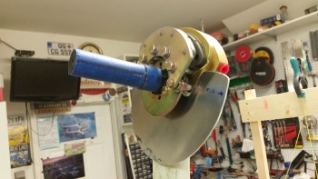
I then bolted on the axle along with the heat shield and the brake assembly. The bolt fit was tight, and needed some persuasion, but it all went together fine.
I removed the blue painter’s tape off the axle in preparation for mounting the wheel, but before I stuck the wheel on I wanted to use the heat shield to check the toe-in angle quickly before proceeding. The toe-in was still right at 0.1″ difference between the zero measurement & the 24″ measurement. With that bit of info, I was ready to mount the wheel & brake rotor.
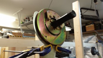
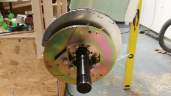
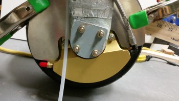
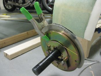
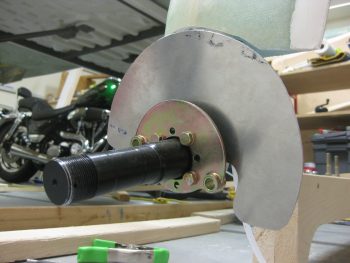
Here’s a side shot of the axle, brake assembly, and heat shield just prior to mounting the brake rotor. The 6 bolts you see in a half moon shape encircling the top part of the axle had to be removed in order to remove the brake caliper assembly, which is a prerequisite step to allow the rotor assembly to be installed.
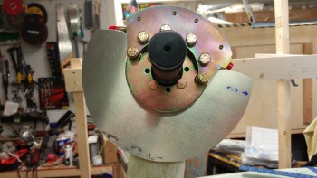
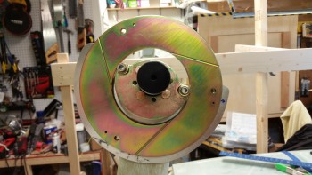
With the brake caliper assembly removed, I then mounted the rotor. If you look at the outer circumference of the brake rotor you’ll note 3 screw holes. These holes are what attach the brake rotor physically to the actual wheel.
You can also see the 1/2″ overhang of the heat shield beyond the outer edge of the rotor to protect the gear leg from the incredible amount of heat the rotor generates during braking ops.
I took the shot below showing how close the brake rotor is to the heat shield. It’s actually a little misleading though since when the brake rotor is bolted to the wheel, the space between it and the heat shield allows for plenty of clearance.
Of course having never mounted one of these wheels before, I wasn’t sure what the rotor- to-heat-shield clearance would be, so I clamped the heat shield tightly against the gear leg to coax it to reside a little closer to the gear strut. Also, in the pic below you can see that I remounted the brake caliper assembly around the rotor. I torqued each end bolt of the 6 caliper bolts to 50 in/lb. and the 4 center bolts to 120 in/lb. as per Matco specs.
I then mounted the wheel, which in and of itself is an odd endeavor since the sealed axle bearing inside the center hub of the wheel is not allowed to rotate with the wheel, but has to be bolted in tightly so that it is secured to the axle –not spinning– and the wheel rotates around it. As noted by Matco, this makes for a very tight install & the wheel bearings will break themselves in as they seat. What this all means is that initially the wheel is pretty darn stiff in trying to get it to rotate. Kinda weird, but hey, I figure Matco knows what they’re doing & I’m not going against their instructions.
With the left wheel mounted, it was time to start on the right side. The first order of business was to clamp the axle in place & drill the 4 bolt holes (not shown).
After I got the bolt holes drilled & the confirmed the axle mounted fine, I then took the axle off & mounted just the wheel/brake mounting flange on the outboard side with 2 short AN4 bolts as guides. I then clamped the popped-off back axle plate back into the correct position on the inboard side of the gear leg.
Here’s a shot of the clamped back axle plate… and me!
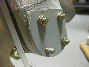
I then drilled the bolt mounting holes in the back axle plate using the 4 axle mounting holes in the gear leg as a guide. As I drilled each hole, I installed an AN4-22A bolt to ensure it fit.
And here’s the back side axle mount plate with the AN4 bolts coming through. Yeah, they aren’t perfectly straight, but I’m confident they’ll do their job.
I marked the profile of the lower gear strut onto the 1/16″ thick back axle plate and then trimmed it down on 3 corners with a cutoff disk on the Dremel tool. I then reattached it with flox since the forward edge of the gear leg underneath dipped down a fair amount since it wasn’t a part of the flox bed that was created when I originally mounted the back plate. I used shorter AN4 bolts to clamp down the aft side of the plate, and used C-clamps to keep the front side of the back plate securely against the gear leg.
After mounting the left wheel, I discovered two important steps that I should have completed before installing the wheel: 1) Attach Fiberfrax to the gear leg since I can’t do it with the heat shield installed, and 2) Install the right angle brake line fitting, which I can’t do … you guessed it! … with the heat shield installed.
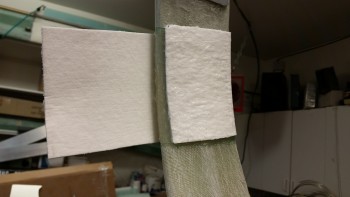
To remedy #1 on the right gear, I broke out the Fiberfrax roll.
I cut off a piece of Fiberfrax that measured 4″ x 10″, and then rounded up my RTV silicone tube & aluminum foil tape.
I test fitted the Fiberfrax & then marked the upper & lower edges, leaving about a half inch spacing on the top (technically bottom) for the foil tape to attach to the gear leg. I actually did this after setting the wheel pant up next to the wheel & gear leg to get a generally idea of the amount of gear leg requiring cover. I want enough Fiberfrax & foil tape to just exit out the top of the wheel pant and have it secured by the wheel pant mounting flange/fairing that will be part of the gear leg.
After marking it, I spread a film of RTV silicone onto the gear leg in-between the upper & lower marks.
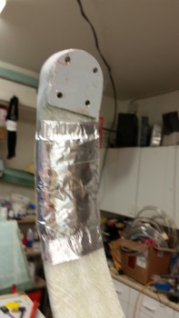
I then attached the Fiberfrax to the gear leg. Since this is 1/8″ thick Fiberfrax, I basically made a tri-fold application, with 1 layer outboard under the heat shield & 2 layers inboard on the backside of the gear.
As you can see, I’m very serious about taking measures to protect the lower gear strut from heat damage from the brakes. In my opinion (ok, and RAF’s too) based on my research, not only should you use the heat shield to protect from the direct heat from the brake rotor, but if using big brakes especially (which I am) and tight fitting wheel pants (sounds like a country song, but I am doing that as well) then the Fiberfrax & foil tape helps protect the gear leg from the heat buildup in the wheel pant long after you’ve parked the bird and started drinking beer & telling war stories, even WITH venting of the wheel pants!
Here’s a shot of the outboard single Fiberfrax layer.
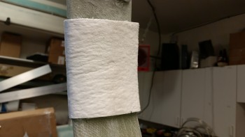
I then wrapped the Fiberfrax with aluminum foil tape, which reading the package I was pleasantly surprised to see it rated for 250° F, which for the tape itself is pretty decent.
With task #1 out of the way, now it was time to proactively accomplish task #2 on the right wheel. I pulled an AN822-3 90° elbow out my tube fitting storage box and located my Permatex thread sealant equivalent of Locktite 567.
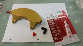
As per instructions, I left the first couple of threads dry & only applied the thread sealant 3/4 of the way around the pipe threaded side of the fitting.
(Oops…. apparently I forgot to get a pic of the fitting installed into the brake caliper assembly, but I’m sure I’ll get a shot of it tomorrow.)
I was planning on installing the second wheel/tire tonight, but when I double checked the toe-in angle I had wobble on the outboard axle mount surface since apparently I didn’t get enough clamp pressure when I was clamping the BID plies down during the toe-in setting. It’s late & I would have to make a real ruckus to sand this down before adding a good bit of flox under the heat shield & then resetting the final toe-in, so it will have to wait until tomorrow.
I did however take a minute to add blue torque seal to the left side wheel bolts.
•••
14 February 2016 — I’m taking a slight detour after I evaluated the gear fairing install requirements (see below).
I started out today by sanding down the sides of the axle mounting face on the lower right leg.
I then floxed the edges of the right lower gear leg axle mounting face and then mounted the right heat shield onto the gear leg. Before mounting the heat shield I waxed the back side of it to make it more easily removable once the flox cures.
After I mounted the heat shield, I clamped on a straight piece of wood & dialed in the toe-in for a final time to let the flox edges cure to create a nice solid base across the entire axle mounting pad.
As I was contemplating installing the right side axle, brake assembly, and wheel, I figured I would check out the foam gear fairing I have on hand from Eureka CNC. On the Eureka CNC website there’s an example of the gear fairing kit install, but it’s for a Cozy. Well, the Cozy gear fairing foam pieces come in halves, whereas the Long-EZ gear fairings come as a single piece with a single slit across the thin underside of each piece. If there’s a way to get the gear fairing pieces on or off without cutting them, I honestly don’t see it. What this means is that I need to install the gear fairings before doing the final install on the axles, brakes, wheels & heat shields.
Here’s another shot of the right side toe-in setting. As for the gear fairing shown below, there’s one more piece that I wasn’t able set in place due to the thickness of the Fiberfrax. When I do install that last fairing piece I’ll have to reshape the foam on the inside of the fairing piece for it to fit.
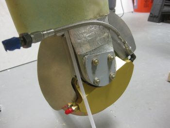
Once I finished my initial assessment on the gear fairing, I removed all of the left wheel & brake assembly off the left gear strut and then installed the 90° brake line fitting into the left brake caliper.
I then mounted the -3 Stratoflex stainless steel brake lines to check how they fit.
Then, probably more for my curiosity, I set up the brake calipers in the configuration that they would be in when installed on the gear legs as they are now on the inverted fuselage.
With the brake line fittings installed on both brake calipers, I then cut another piece of 1/8″ thick Fiberfrax 4″ x 10″. I then test fitted the Fiberfrax piece on the left side gear leg. I marked the area and then covered it with a good coat of RTV Silicone adhesive before putting the Fiberfrax in place.
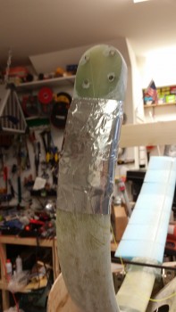
The pics below show the Fiberfrax set in place on the left gear leg.
I then covered the Fiberfrax with foil tape.
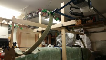
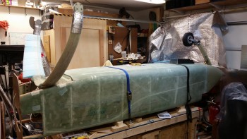
Although I don’t have the wheels installed, since I’m moving into a new phase on the main landing gear, I figured I would take a shot with the mini-“Straight Tower of Pisa” taken down.
•••
15 February 2016 — I started out today finalizing my research on relief tube installs. I was checking out other builders’ sites to ensure I didn’t miss any good tips for installing the relief tube.
Although my class was canceled tonight due to the storm (as you can see in the pic below!), I then spent a few hours working on my course work. I then spent another good hour+ shoveling snow.
After I got the snow cleared off my truck, I ran to the Aviation Department at Home Depot to pick up some 1/4″ OD for the relief tube and some 7/16″ OD tubing to embed in the gear fairing channel. I found the 1/4″ OD tubing but they didn’t have any thin-walled 7/16″ OD tubing, so I ended up buying 1/2″ OD and I’ll see if I can make it work.
After getting back home, I mocked up the 1/4″ tubing on the left gear leg. For the record, I did check out using Nylaflow for the relief tube but I didn’t like it since it’s just so darn stiff & unwieldy. I’m glad I picked up the 1/4″ polyethylene tubing at Home Depot since it’s much more flexible than Nylaflow.
After a few more tweaks of the tubing on the left side gear TE, I then micro’d & glassed the relief tube in place using 1 ply of BID. I then peel plied the layup. Since this layup will be covered with micro and the gear fairing foam pieces, I went ahead and use some old MGS 335 epoxy & hardener that I had on hand.
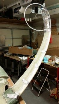
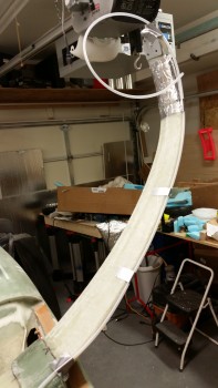
Here’s a shot of the top side of the gear showing the relief tube glassed in place.
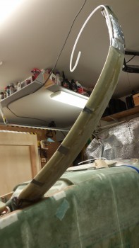
After a few hours under the heat lamp, the layup to attach the relief tube to the main gear TE was pretty much cured. Here’s a couple pics of the cured layup.
•••
17 February 2016 — As you can see, and as I predicted, I didn’t get anything done on the plane yesterday since my fellow Long-EZ builder & great friend Marco (prolific writer of the awesome blog “What have I gotten myself into!”) stopped by late yesterday afternoon. I showed him around the shop and gave him the tour & update on my project, which he hasn’t seen in person since he helped me layup glass on the F22 bulkhead back in 2011!
We talked all things Long-EZ, flying & otherwise until the wee hours of the morning before finally hitting the rack, then continued our discussion this morning. After a late lunch he took off back home & I got back into the shop. It’s great to be able to visit with good friends for more than just a couple of hours, and since Marco & I started our respective Long-EZ build journeys at the same time, after having met at the EAA composites workshop, we know each other’s projects just about as well as our own. And as I mentioned to Marco over lunch, having a building buddy –even more & above just being linked into the canard community– has really made my build much easier and faster in almost every aspect.
So late this afternoon I started on the gear by knocking out the first half of Long-EZ Plans Change (LPC) #128 that’s listed in CP-48. It basically says that a few pilots had knocked their gear loose off the LGMAT tube and had to recenter the gear with a crowbar. Then they ensured it stayed centered by placing flox in-between the gear tab and the 2024 aluminum gear mounting tab thus creating a thick flox washer between the two to keep the gear tabs in place both on the front & aft side of the gear.
Instead of trying to do this after the fact, if it ever came to it, and since I have no delusions of being the best pilot in the world or the fact that I won’t have a few hard landings, I thought it best to get this flox into these channels now while I still have good access. For the record, I spent a good 10 minutes going over my build schedule and thought hard to see if I could come up with any scenarios where I would need to remove the gear for the rest of the build, and couldn’t come up with one. So, in goes the flox!
I started by using my Perma-Grit tools to sand the glass gear tab opposite the landing gear mount extrusion so that the flox had something textured to bite into.
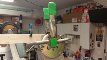
To better keep the flox in place, I then cut up 4 plastic strips 1/2″ wide off an old package & wrapped them around the bottom of the gear tab (technically top since it’s all upside down) and butted up against the inside edge of each aluminum extrusion. I then taped the plastic strips in place to essentially create a “U” shaped channel.
I then whipped up some epoxy with fast hardener and made some wet flox and poured it into each U-shaped trough I created around each of the 4 gear tabs. Obviously, this will only cover about half of the area, but by starting out with wet flox I know I’ll get good coverage in the hard to reach areas. The “top” half will get a little bit thicker flox since the lower base half will be in place with the cured wet flox.
I then whipped up another batch of flox using MGS 285 with fast hardener and finished my flox gear washer mod IAW LPC #128 as described in CP-48. I used slightly thicker flox this time since I didn’t have any dams to stem the flow of flox from running off the “top” half of each gear tab-extrusion gap. You can also see that I had just spent a few minutes removing all the tape, plastic & errant flox from the “bottom” half flox application.
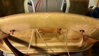
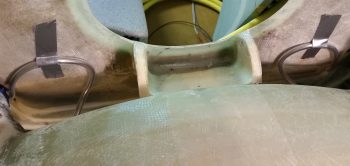
Here’s the new aft side flox “donuts.”
And the forward side flox gap fillers.
I won’t be glassing the top sides of the gear fairings until after I flip the fuselage right side up.
•••
[NOTE: Over the past 2 weeks I installed the main gear leg fairings. See Gear Leg Fairings page for fairing installation details.]
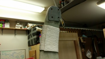
27 February 2016 — I started off today by test fitting the right heat shield onto the gear leg. The foam of the lower gear fairing extended out enough to make it impossible to mount the heat shield in its correct position.
I marked the perimeter of the heat shield onto the lower gear leg in preparation to cut the glass & foam away from the lower gear leg.
I then used the Fein saw to cut away the glass & foam away from the lower gear leg to allow the heat shield to fit correctly in place.
Here’s a shot of the trimmed lower right gear leg.
I then remounted the right gear heat shield, which fit fine. I held the AN4-22A bolts in place with spring clamps.
I then repeated this process on the left side to clear the lower gear leg glass & foam (and micro) to allow the left heat shield to fit correctly.
I ran a line down the fuselage CL to double check the toe-in, and even sanded the gear axle mount pads, but after dialing them in as best I could I realized that I was about as close as I was going to get at this point. I’ll do some final checks with the fuselage actually sitting on the ground.
After messing about with the toe-in and dialing it in as best possible, I then mounted the axle, brake mount assembly and the heat shield onto the right gear leg.
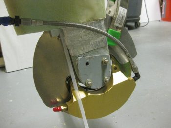
I then mounted the right brake rotor and brake caliper assembly.
Here’s an inside view of the right brake caliper assembly.
I then installed the wheel & tire onto the right side gear leg.
Here’s another shot of the right wheel installed.
After installed the right wheel, I installed the left axle, heat shield and brake mount assembly. Unfortunately, after tightening up all the nuts on the AN4-22A bolts and then attempting to mount the rotor & brake caliper assembly I realized that I had mounted the brake mount assembly upside down… doh!
This is how it should look!
I then mounted the left brake rotor & brake caliper assembly.
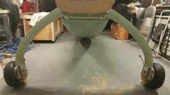
Here is a shot that I’ve been wanting to take for a long time: both wheels mounted!
I then mounted the 9.5″ braided stainless steel Stratoflex brake lines that will connect the brake caliper to the stainless steel brake line tubing.
Here’s an inside view of the right (top) and left (bottom) braided stainless steel Stratoflex brake lines.
I then mounted the wheel axle nut sleeves to both Matco axles. These are sold by Van’s Aircraft for mounting the outboard side of the wheel pants.
With the gear fairings finished and the wheels now mounted, I will start the process of installing the wheel pants. After I get the wheel pants installed, I’ll then flip the fuselage back over, finalize installing the brake lines. Finally, I’ll then work on the RAM air scoop and aft fuselage extension over the hell hole area.
•••
2 March 2016 — Tonight was a milestone in that it was the first time the fuselage has rested on the main wheels … ever!
I lowered the fuselage dolly platform to get the fuselage as low as possible to slide it aft on the fuselage dolly and thus get the main gear wheels on the floor.
Forgive the camera angles, but I was backed up all the way in the corner and trying to get as wide angle of a shot as I could!
After I got the fuselage set so I could access the CL on the belly, I started attaching straight edges, running strings and plumb bobs, etc. to double check the toe-in on each side. As I suspected, I jacked up the toe-in pretty good after I had set them correctly from the first go around with the gear in the air.
When I flipped the fuselage over I had double-checked the toe-in and it seemed to be either negative (wheels pointing out) or not enough. So when I mounted the wheels I sanded down the mounting pads to reset the toe-ins correctly. Of course, as often is the case, I should have left well enough alone!
With access to the CL mark on the belly this evening, I could actually determine the CL to double check my toe-in measurements. After it was all said & done this evening, I confirmed that my left wheel assembly is mounted approximately .08″ farther outboard than my right, which is not enough for me to worry about any further.
However, my toe-in is much more than it technically should be with each side a hair over 0.3″. I figure that per plans the max you want to be at is 0.45″ combined, and I’m sitting just under 0.65″ combined. However, since my plane will have a bigger engine and weigh a couple hundred pounds more than what Burt was originally planning these birds to weigh in at, I’m not going to make something not-so-great even worse by mucking about with it. At least not right now. I’ll wait until I do my high speed taxi tests to see how my tire wear is progressing & then adjust fire from there.
•••
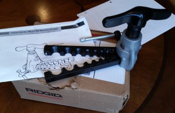
8 March 2016 — First off, UPS delivered my Ridgid 37° flaring tool yesterday morning. This tool will enable me to flare my 3/16″ stainless steel brake tubing, thus allowing the final pieces to placed into the brake line system. Now, this tool’s specs does not specifically state that it’s rated for stainless steel, but many of the reviewers on Amazon did clearly state that they used it with very good results on stainless steel. So I figured I would give it a try. I will tell you that it is much bigger than it looks in the pics, and this thing is a heavy, robust beast.
Secondly, I’ve been doing a fair amount of research on my toe-in dilemma and I’ve decided to pull the wheels, configure the fuselage upright without the fuselage dolly in the way and do one final toe-in setting to get them to specs. After reviewing both the plans, what other canardians have done, and even the standard on other types of aircraft, I’m concerned my toe-in is too much, even for a heavier than plans bird. I would probably not mess around with it if it were, say, 0.5″ total vs. the 0.45″ total called out for in the plans, but I’m significantly over at 0.6+”.
Finally, I’ve been updating my to-do task list and one thing I forgot to add came up today when I took a couple of pics to send to Marco earlier. I was pointing out how the aft tab of my right heat shield was just barely kissing the brake caliper… as I’m pointing to in the pics below. I’ll trim about 0.1″ off that area when I remove the wheels (AGAIN!) to set the final toe-in.
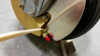
As you can see, the left side heat shield clearance is fine.
•••
9 March 2016 — Today was quite the beautiful day here in Northern Virginia, so after messing around with my school work for a couple of hours, getting my motorcycle battery charged up enough to get it started and out for a quick scoot, and then spending just over an hour on the phone with my building nemesis Marco (ha!)…. I finally got into the shop!
My main goal for this afternoon was to get the fuselage off the dolly and into its grazing stance, which I did as you can see below. Before I actually offloaded the fuselage from the fuselage dolly, I did a bit of Spring cleaning in the shop and attached the rollbar and headrest to the fuselage.
My next task was to install the battery in the nose and connect up the wiring leads to get the nose gear to extend and finally get this bird on all 3 wheels!
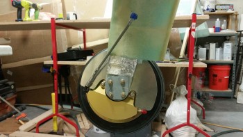
First, I wanted to get a couple of shots of my grazing fuselage from the aft end.
Especially this shot, where the nose is fully resting on the nose bumper, which of course is the aerodynamically clean shaped nose bumper that my buddy Marco CNC’d out of a hockey puck. He did a fantastic job on it!
I shot a video that covers the majority of work I’ve completed over the last few months. Then, at the end of the video, I raise the nose by extending the nose gear for the first time during this build. Note that I merely strapped in the battery, attached the leads, and then shot the video. There was no previous testing to ensure it worked and the initial nose raising in the video is just that, the initial nose raising in real time. I’m just glad it worked! Whew!
I took one final pic of the fuselage on all 3 wheels before closing up shop for the evening. This of course is another huge milestone for this build!
•••
24 August 2016 — I started out today by updating my Master Project Build Schedule which I call my “Order of Battle.” I figured I need to start with the master schedule to better detail what tasks that I am specifically going to do on my Chapter 9 To-Do sheet. In doing so, I broke out the hell hole cover and RAM air scoop steps for a later date after other prerequisite tasks are completed.
I then set about to figure out this pesky toe-in issue that needs finalized. I put the fuselage up on a fold out table vs. fuselage dolly so that I could get a clear shot of the CL & the front gear leg.
I started by leveling the longerons side-to-side. I also clamped a board onto the table legs perpendicular to the fuselage and then positioned the fuselage so that the axles were set back from this board 24″.
I then removed the wheels/tires, brake disks and pads off of each axle.
At this point I needed to find the aircraft CL, so I shot a laser line which allowed me to check the toe-in of each wheel not just in comparison to each other, but to the CL as well. I took the pic below a little off center, that’s why the line seems a bit askew.
I then clamped a 24″ square to each side and checked the toe-in. The plans say that the max toe in delta between the “B” measurement (at the axles, or 0 inches) and the “A” measurement (at 24″ forward of the axles) should be between 0.2 and 0.45 inches. Right now, I’m sitting at 0.62 inches, with my right wheel toed-in 0.08″ more than my left. If I can get the right wheel toe-in the same as the left, then at 0.54″ I’ll be happy and call it a day. This may be a bit more than Burt called for in the plans, but then again, my aircraft weight is a bit more than what Burt advised as well. One other thought is that I’m not going to jump through a lot of hoops now until I start doing some high speed taxi tests & a few landings, at which point I’ll tweak what needs tweaking! (I made note of these points back in March as well).
Now, a few more figures. Before I took the wheels off I measured from the front center of each tire near the ground to the large nut on the nose wheel fork. Each side came out very close to 110″. Then, after I removed the wheels I also measured from the bottom of each axle to the 6-foot level I had across the longerons, with each side measuring close to exactly 48.5 inches. I then measured from the aft side of each of the inside, top-forward axle mounting bolt to the fuselage CL at the back edge of the fuselage bottom: Right side 34.32″ and left side 34.25″. I also checked the dip angle of each axle hanging free, both came out to 12.4°. Finally, with the longerons level I laid the long level across the squares as close to the gear legs as possible: perfectly level as well!
So . . .
Interestingly, when I checked the distance between the end of each axle, straight out perpendicular to the fuselage, I kept coming up with the left side axle end being 0.7″ closer to the fuselage than the right side! I did this a number of times, in a number of different fashions, and each time it told the same story. Very odd! The only correlating data that helps support this –that I didn’t mention above– is that through my “A” & “B” measurements for the toe-in, I again measured that my left AXLE is 0.33″ closer to the centerline than is my right. This actually makes some sense, because I mistakenly added nearly 0.2″ more BID to the right side gear leg due to my misID’ing the CL when the fuselage was upside down and I read the wrong mark on the freshly extended firewall.
My conclusion is that I MAY add a spacer to help clean some of this up. I talked to my buddy Marco and he advised to leave it and press on (good advice), but a big factor in this decision will be the affect it has on the asymmetry between the wheel pants. I’ll being doing a fair number of measurements tomorrow on those in prep of installing the wheel pants. In short, more to follow on this.
In other news, I was able to trim the offending right heat shield on the aft side where it was barely touching the brake caliper (actually visible in last pic above). I also topped off the tire pressure raising it to the recommended 70 PSI from the 50 PSI I had filled them up to (actually, after 6 months, both tires were down to 30 PSI each).
•••
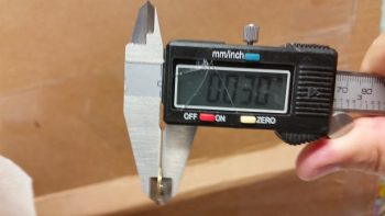
25 August 2016 — In pondering how to fix the Right side toe-in that points inboard just a tad too far, I considered using AN960-416L washers as shims on the forward axle bolts to kick the toe-in back out.
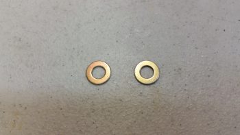
But that turned out to be a no-go, since these washers are a 0.030″ thick. That would equate to over 0.3″ back outboard at the 24″ forward (of the axle) mark, in effect creating a toe-out vs. toe-in! So I did the math and concluded that I actually need a 0.007″ shim, which would result in the right wheel’s toe-in very closely matching the left.
I removed the Right side axle bolts in prep for eventually installing shims on the forward 2 bolts. In addition, I’m going to swap out the longer axle bolts for slightly shorter ones.
•••
7 September 2016 — Today I received my Wheel Bearing Packer from Amazon, which I used later in the evening to facilitate putting the main gear wheels back together. I’m still shooting to the wings mounted prior to this year’s Rough River. If I can get my plan into motion I’ll need to be able roll the fuselage around on all 3 wheels, which means the main gear wheels need to be remounted… properly!
I grabbed the packet of 0.007″ stainless steel washer shims that I got from McMaster-Carr and pulled out a couple. I then removed the axle & brake caliper mount assembly and swapped out the longer bolts with shorter AN4-21 bolts. I then put a thin 0.007″ shim on each of the forward axle bolts. Although these washers are very thin, the affect at 24″ inches forward of the wheel is that they should kick the toe-in out enough to match the left side toe-in and distance from centerline.
I remounted the axle, brake caliper mount and heat shield. Since I wanted to get to packing the wheel bearings with grease, I left the torquing of the brake assembly bolts until tomorrow.
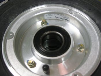
Here’s my freshly delivered wheel bearing grease packer:
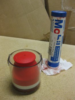
I grabbed my tube of aviation grade grease . . .
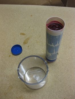
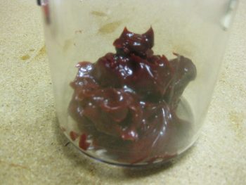
and put a good amount of it in the bearing packer cup.
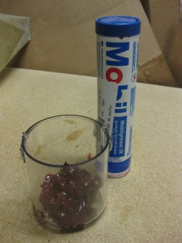
Here’s a close-up shot of the Mobilegrease 28.
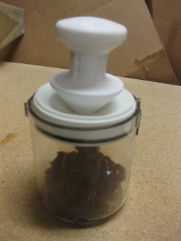
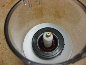
I then reset the inner base with its integral o-ring back into the cup.
And grabbed the first wheel bearing off the right wheel to test out my new toy.
Here it is, all set to go. Just need a good bit of pressure to get the grease to squeeze into the bearing cups.
Like this.
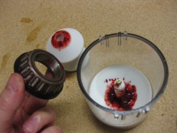
Here’s a couple shots after with the upper plunger body removed.
I then removed the bearings from the cup, cleaned off the excess grease, and reset them back into the wheel. Before actually seating the bearings, I cleaned the race with a very light coat of grease.
Here’s bearing #2 after getting packed with grease. I have to say, this wheel bearing packer works pretty darn good!
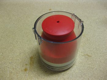
After I finished packing all 4 bearings (2 per wheel) I set the red cover into place to keep the grease fresh & clean, and cleaned up the grease on the tube & recapped it.
•••
8 September 2016 — My first task of the day was swapping out the longer AN4-22A axle bolts on the left gear for the shorter AN4-21A axle bolts like I did on the right side gear leg. This didn’t really take long, but eventually I did have to remove the brake assembly to get to the axle bolts (remember this key point!).
Actually, I was able to swap out 3 of the 4 axle bolts, but I just couldn’t get a wrench on bolt head of the aft bottom axle bolt (it sits right next to the axle… too close for a socket).
Here’s a shot of the axle bolts: new AN4-21A on the left and old (longer) AN4-22A on the right.
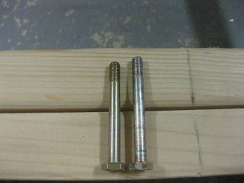
You can see the last holdout below, the whole reason why I had to remove the entire brake assembly (again, remember this point!).
Here’s a shot with the brake caliper assembly removed and all the new shorter axle bolts in place.
I then reassembled the left side brake assembly. I torqued all the bolts to the proper specs as outlined by Matco. I also torqued the right-side brake assembly bolts as well, but something wasn’t right and I ended up dismantling & remounting the entire right side brake assembly again. The second time was a charm and the brake disc aligned correctly between the pads & I was able to get the bolts torqued to the correct values.
Although I didn’t get a shot of the wheels, I then remounted the wheel/tire assemblies with their freshly packed bearings. I then went upstairs to review my notes on the wheel pants, only to find a discussion from Bernie Siu on how each time he modified the inboard wheel pant mount assembly, he had to totally dismantle the wheel assemblies TO GET TO THE AXLE BOLT HEADS TO REMOVE THE INBOARD NUTS to swap the inboard wheel pant mount…. Doh! I guess this won’t be the last time I mount those wheels, eh?!
•••
24 March 2018 — I started off today by removing the engine mount –which was a tight fit– exposing the 4 engine mounting extrusions.
 When I was making up my 3×5 card task list this morning, I also decided to verify my desired locations for the right and left brake line runs. I wanted them below the main gear so they were as accessible as possible via the bottom Hell Hell cover (disguising itself as an intake scoop) once the plane is completed.
I confirmed the positions and sanded down the areas that would get a few plies of BID to secure the Clickbonds into place. BTW, the Adels that are getting mounted to these Clickbonds won’t directly clamp to the brake lines, but rather will secure each side’s 3/16″ (from the wheel calipers) to 1/8″ (fuselage brake line run) Generant reducer fitting.
As the 5-min glue set, I then prepregged all the BID for laying up over the Clickbonds.
Just before mixing up some epoxy with fast hardener, I wrapped each Clickbond threaded post with a small piece of electrical tape to protect against any epoxy gunk.
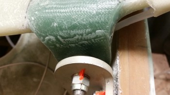
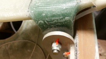
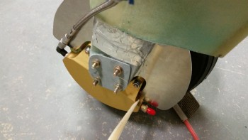
Here are the cured BID layups for the lower right (upper pic) and left brake line securing Clickbonds.
•••
26 March 2018 — I started off today assessing the configuration of all the hell hole components and the wires in, around and through the hell hole.
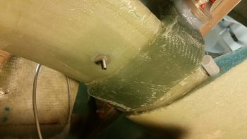
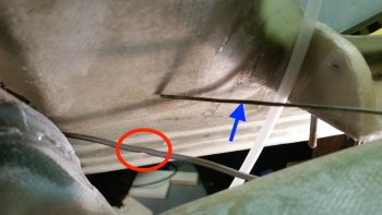
I then started my shop tasks today with a small repair. Yes, hard to believe that any of the 1/8″ aluminum brake line tubing coiled up in the hell hole since 2012 would ever get a ding or scrape on it . . . well, folks, the unthinkable happened! On my left brake line, about 6″ where it exits the lower fuselage, the tubing had a visible dent/crimp in it (circled in red in pic below).
My goal this morning was to either extricate the dent/crimp and repair the line –without destroying or mangling it– so that it would function as designed, or go with the nuclear option if need be: cut the line at this point and tie in the brake line coming from the wheel farther forward than I had planned.
By my calculations I was dealing with a 0.075″ diameter hole, and I measured a piece of hanger wire that I’d be using at 0.069″ …. Hmmm, seams like it should work (blue arrow in pic below). I filed the tip smooth and hit it with Acetone to clean it. But it proved just a tad too thick. Plus, it wasn’t as arrow straight as I would prefer.
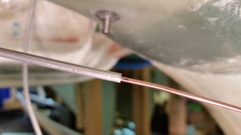
After pondering a bit, Voila! I found the solution, pressing a perfectly straight and slightly narrower TIG welding rod into service. I marked a point on the rod that was past the offending dent in the line, and slowing worked the rod, and aluminum tube, to get the rod though the tube and remove the pinch in the line.
Here you can see I’ve reached my mark, denoting that the 1/16″ welding rod is clearly past the offending pinch in the brake line. I then worked the both the welding rod and tube for a good 10-15 min longer just to ensure that the dented section was as opened back up as close as possible to full diameter.
I wanted to institute some service loops for the brake lines and had some initial thoughts about using Adel clamps or some other means to keep the tubes in place. Not only did I want to keep the aluminum brake line tubes themselves clean in the event I may need to use them for any reason in the future, but I definitely wanted to protect them as well, especially since I do plan on jamming stuff into the hell hole for storage during flights.
I tried Nylaflow but the resulting loops against the lower aft side of the GIB seat back bulkhead proved too tight for Nylaflow. I even tried working the Nylaflow into a nice loop before placing it on the brake line, but it just kinked on me when the radius got too tight. Looking around the only thing I had on hand was the clear tubing I was using for the engine dehydrator, so I stole a couple of lengths off the line and pressed them into service.
Since the tubing will be out of the sun and under what we Canardians typically do in situations like this –bury it micro and throw a couple plies of BID on top!– I wasn’t overly concerned that it’s not “aircraft grade.”
After the protective clear tubing was in place over both brake lines, I then cleaned up the ends of aluminum tubing and temp mounted them in their respective reducer fittings. I then mounted the reducer fittings in their respective Adel clamps. That gave me a starting point to finalize the size and configuration of my brake service loops, which I then taped in place.
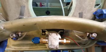
Here are Before & After pics of the right side brake line set in place and then with the service loop micro’d and glassed in place with 2-plies of BID . . . I used 2 plies to help protect the brake line against any untoward pinching. Obviously brakes are quite a useful thing in fast landing aircraft like Long-EZs.
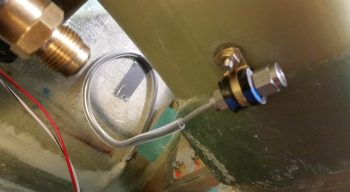
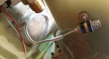
And here are Before & After pics of the left side brake line set in place and then with the service loop micro’d and glassed in place.
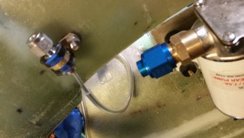
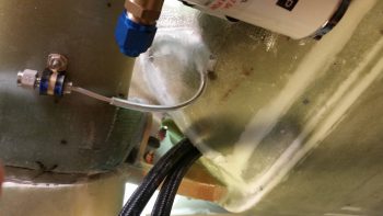
A different view of the right side brake line with the service loop micro’d and glassed in place.
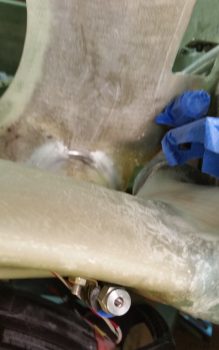
Left side brake line with the service loop micro’d and glassed in place.
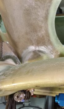
•••
29 March 2018 — Today I spent well over 2 hours shaping, cutting and installing the 3/16″ stainless steel brake line tubing that runs through the plastic tubing channel that I glassed into the gear fairing, situated on the TE of the original gear bow.
Shaping the right side brake line was a little trickier because I had to go up, over and around the big yellow power cables. I had considered looping aft and below the cables, but I wanted as little brake line as possible hanging out unsecured in free space. So I went up and over the big yellow cables. I spent well over 2/3rds of my time working these brake lines on this right one.
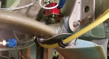
The left was significantly easier, although bending stainless steel is not the easiest, daintiest of endeavors to undertake –especially when small bends or curves are required on a small length of tubing. But through persistence I finally got both stainless steel brake lines routed through the gear legs and installed in the 3/16″ to 1/8″ Bi-Lock reducers (thanks to Dave B. for the gouge on those!).
All that is left now (although not a significantly EZ task) is to cut these lines near the wheels and cross connect them to the 9.25″ long -3 stainless steel hoses that are the final link in the brake line chain.
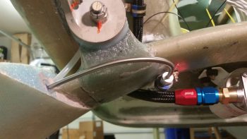
I like this pic below because it shows the oil heat pump, finished right brake line and secured big yellow power cables.
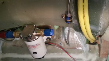
•••
5 April 2018 — Two things had to happen before I would get to the point that I was ready to glass the bonnet onto each wheel pant. The first was a WANT and was related to making the second REQUIRED task a little easier . . . attaching the 3/16″ SS brake line to the 9.25″ SS braided brake line coming from the brake caliper.
I started by removing the lower part of the gear leg fairing that was situated inside the wheel pant. With both wheel pants in place I marked the gear leg opening of the wheel pants to depict the no-kidding line where each wheel pant intersected the gear leg. Just to ensure that I had no clearance issues pop up on me, I dropped the line down approximately another 1/4″ as my cut line.
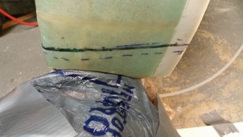
I then removed the extraneous portion of the gear leg fairing that would have been inside the wheel pant whenever the wheel pant was mounted. Not only does this give me more maneuvering room and space inside the wheel pant and saves a tiny bit of weight, but the main thing is that it allowed me access to the brake line that runs inside a plastic tube inside the gear leg (visible just aft of the gear fairing mid-point in the pic below).
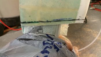
I then eyeballed how the brake line tube plastic conduit traveled up through the gear leg fairing. Now, hindsight being 20/20, if I had known then what I do now, I would have simply ordered a 6″ long -3 braided SS brake line . . . but I didn’t, and these things are expensive as all get out. I don’t normally like burying things that are a probably a good idea to have access to when there’s a potential spot for leaks (aka “fittings”). So if required, I’m making this so I can simply cut out a rectangular piece of glass and have the fitting right at my disposal… it won’t be pretty, but it will be accessible, in a PITA sort of way.
Optimal? No. Am I doing it? Yes. I figure unless there’s a leak, it will most likely serve as any other brake line does in these birds and become a distant memory of the oddball installation.
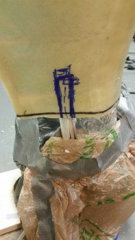
I cut out a channel a few inches high to gain access to a good portion of the 3/16″ SS brake line that I had just ran last week into the hell hole.
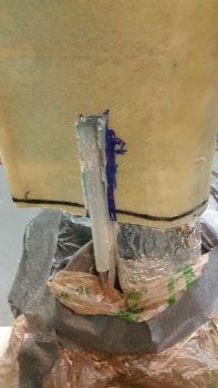
I then managed to get the plastic tubing conduit cut away. What I was after here was enough length of brake line to bend it out, flare it with a fitting end attached, and then stow it away (bend it) back into the gear leg fairing.
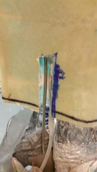
With the length of the -3 hose, I needed access to a bit more tubing to cut and flare the end, so I cut a narrower channel going up the gear leg fairing. This allowed me to pull enough of the brake line out to cut it, then flare it.
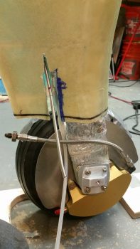
Which is exactly what I did, with just the barest amount of space enough to get the crimping tool on the end of the 3/16″ SS brake line.
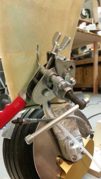
But I prevailed in the end, with a pretty decent flare if I say so myself (smile).
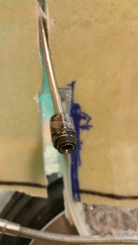
I then shoved it all back into the ugly gaping channel that I had just made on the inside of the left gear leg fairing.
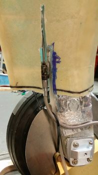
I then did the same thing with the right brake line on the right gear leg fairing.
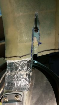
Then, just as I did on the left gear leg, I connected the 9.25″ -3 braided SS hose to both the brake caliper fitting and the (now) in gear leg fairing 3/16″ SS brake line fitting. This finishes the brake line run from wheels all the way to master cylinders.
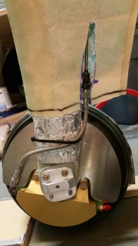
I forgot to snap any pics, but my next task was to whip up some thick 30/70 flocro paste (heavy on the micro) and embed just the 3/16″ SS brake line in the gear leg fairing. This was after I wrapped the fitting in protective plastic wrap and covered it with a piece of electrical tape. To be clear, the fitting did not get any flocro covering it, just the brake line tubing.
•••