
Chapter 7 Step 2 – Glassing the Fuselage Exterior
15 June 2012 – And so begins the final chapter in the saga of glassing the fuselage … or should I say the final step . . . of the chapter!
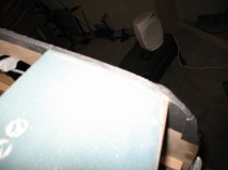
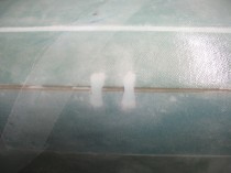
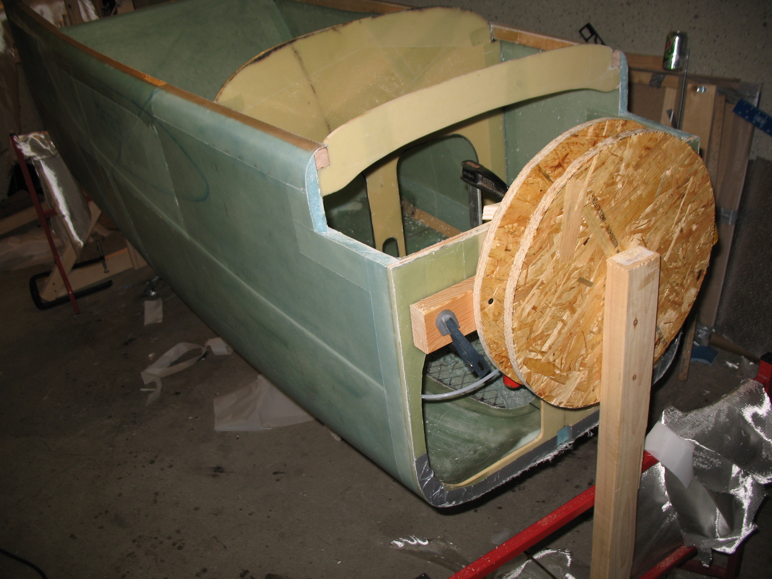
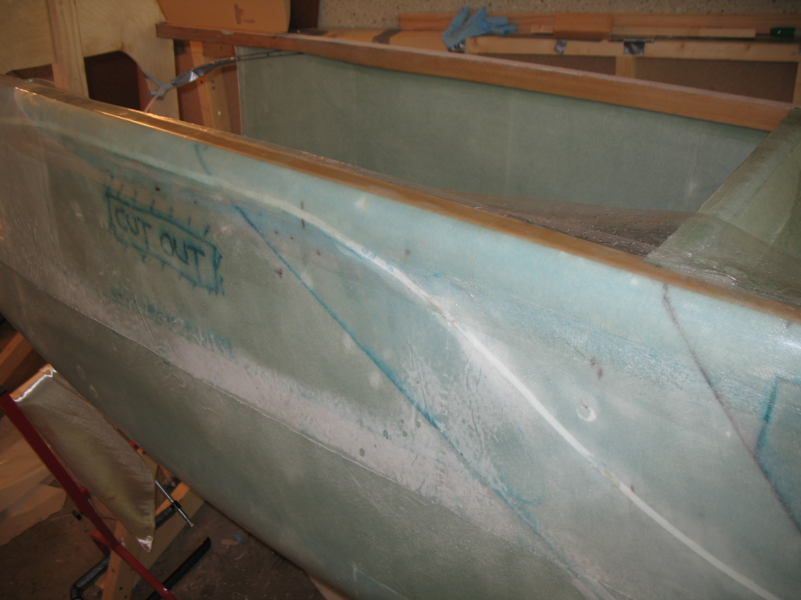
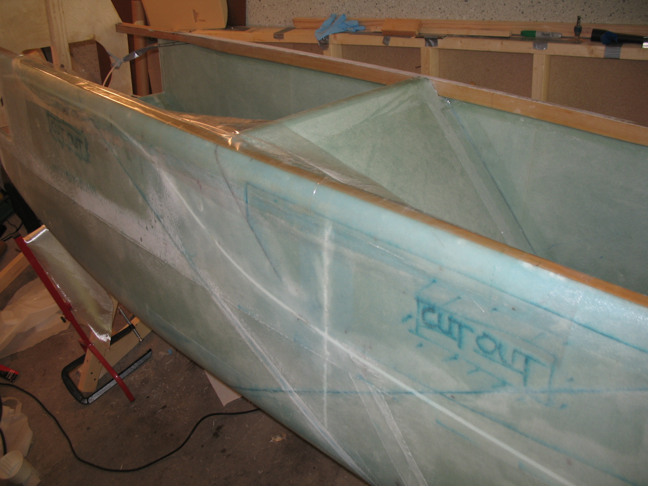
I pulled an all-nighter to glass the fuselage. The first the few hours were of course all about prepping EVERYTHING to get ready to actually start glassing. Below is a pic of the final filled-in foam strip at the rear of the fuselage.
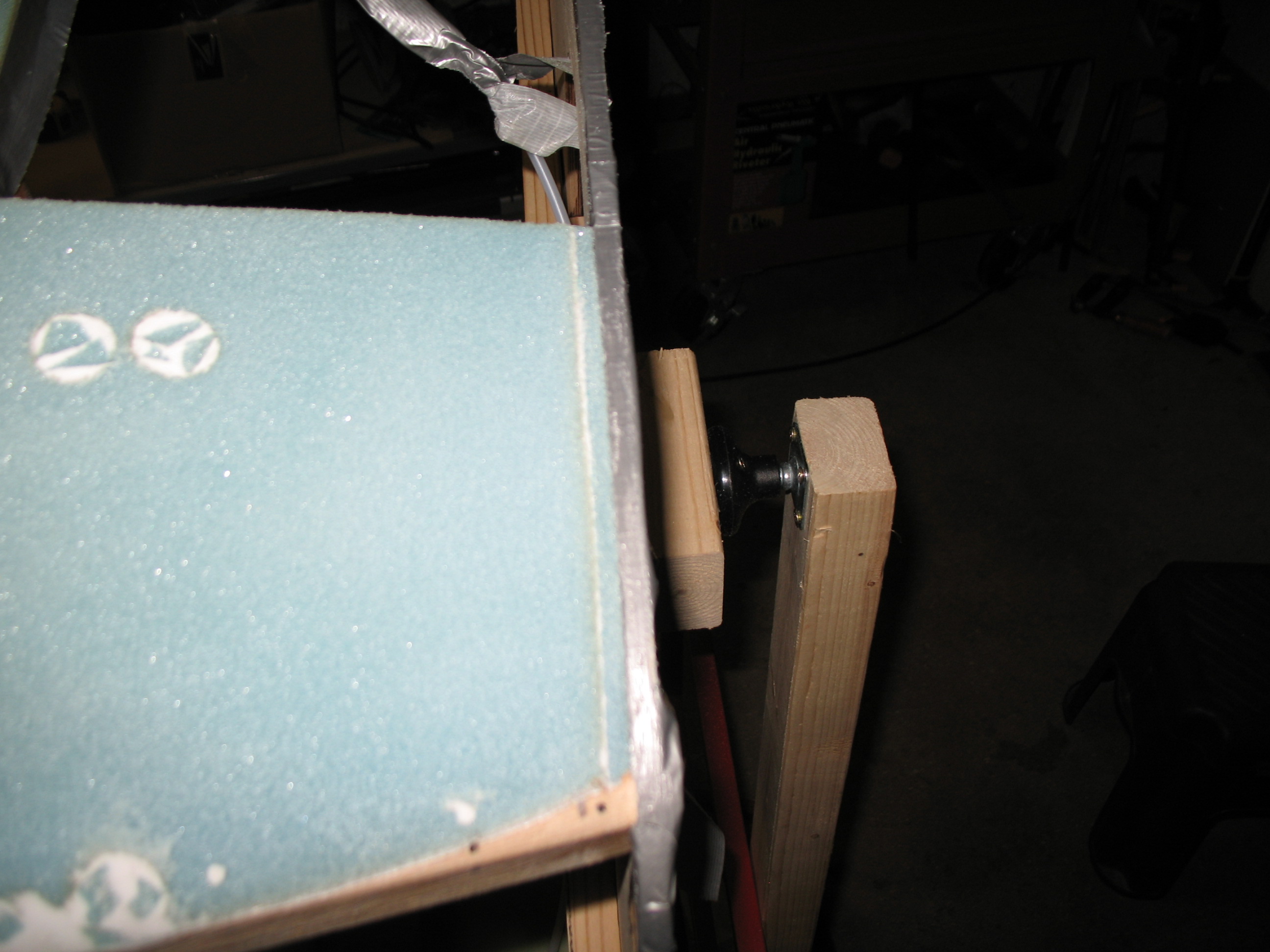
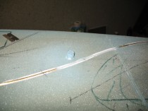
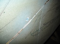
I also reset the Left-side fuselage thread insert and filled the hole from the outside with a foam plug. Here’s the view of the insert installation from the outside, with the plug foam still sticking above the surface at one point.
I cut two sets of 3″ UNI strips at 50″, 52″ & 50″ and set them up “pre-preg”.
I cut 2 pieces UNI for the third ply on fuselage & wrapped/rolled in brown paper.
I cut a UNI roll at 30° on the end and took it out the garage.
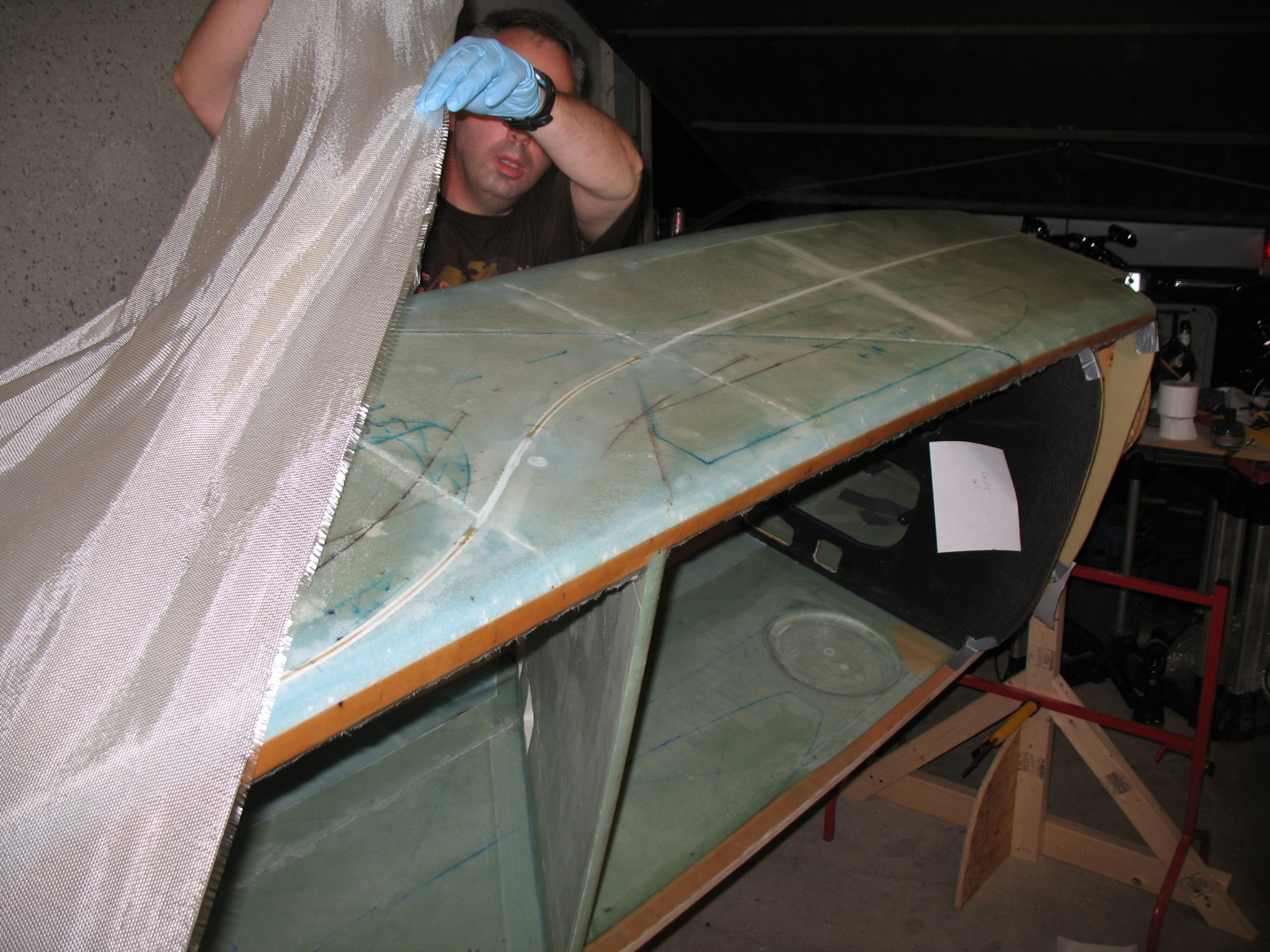
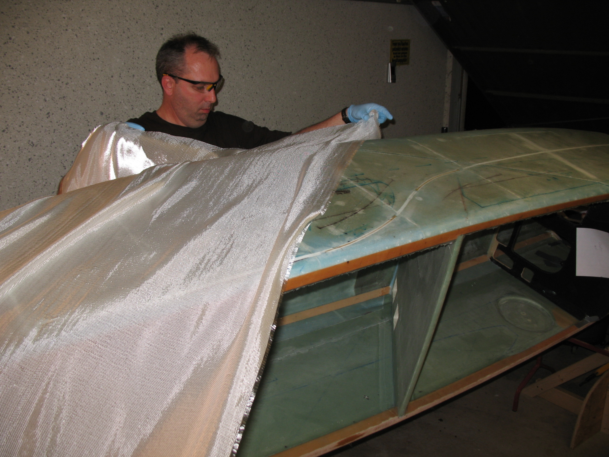
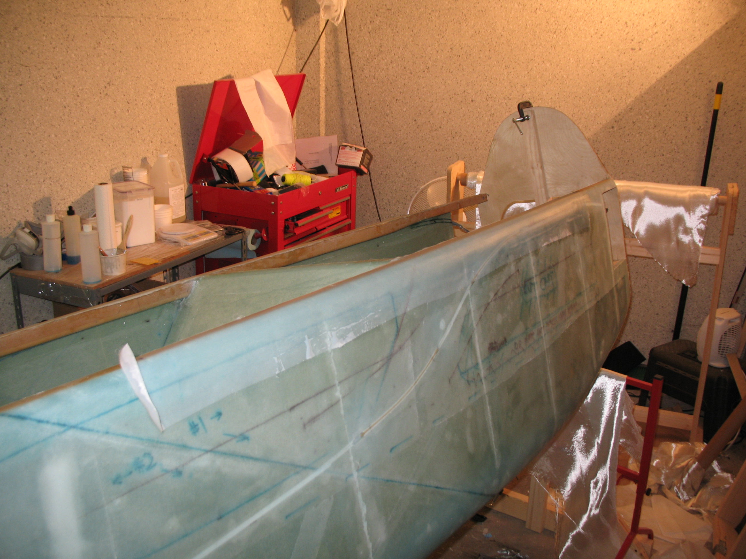
By the time I actually got started glassing, it was about 1930 in the evening. I glassed straight through until about 1430 the next day, after peel-plying critical areas and seams and trimming glass so it would cure nicely at the edges. In that whole time I may have take about four 5-7 min bathroom/snack/water breaks. Being by myself (minus the 10-minutes my buddy Kevin stopped by and took some pics with my camera), it was definitely a marathon glassing session. In retrospect, if I glass another fuselage by myself, I’ll most likely either stop half-way through, or pre-cut all my glass so it’s ready to go!!


•••
16 June 2012
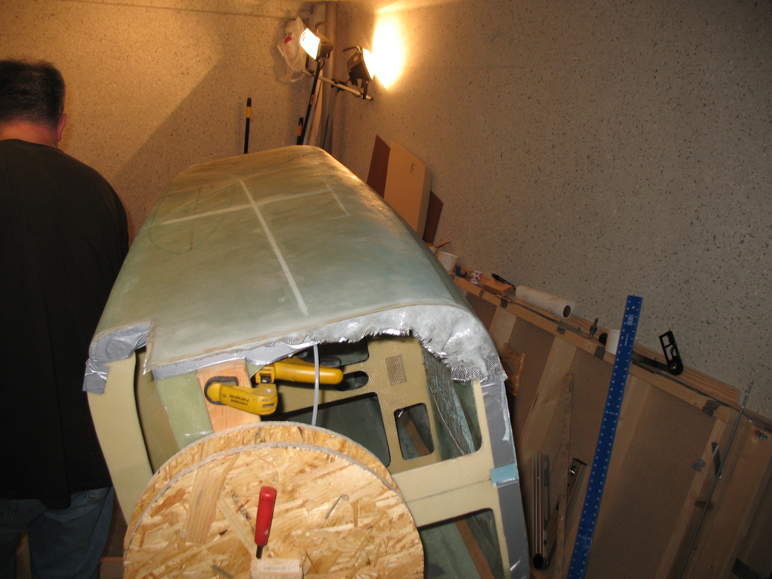
The glassing continued on well into the evening . . .
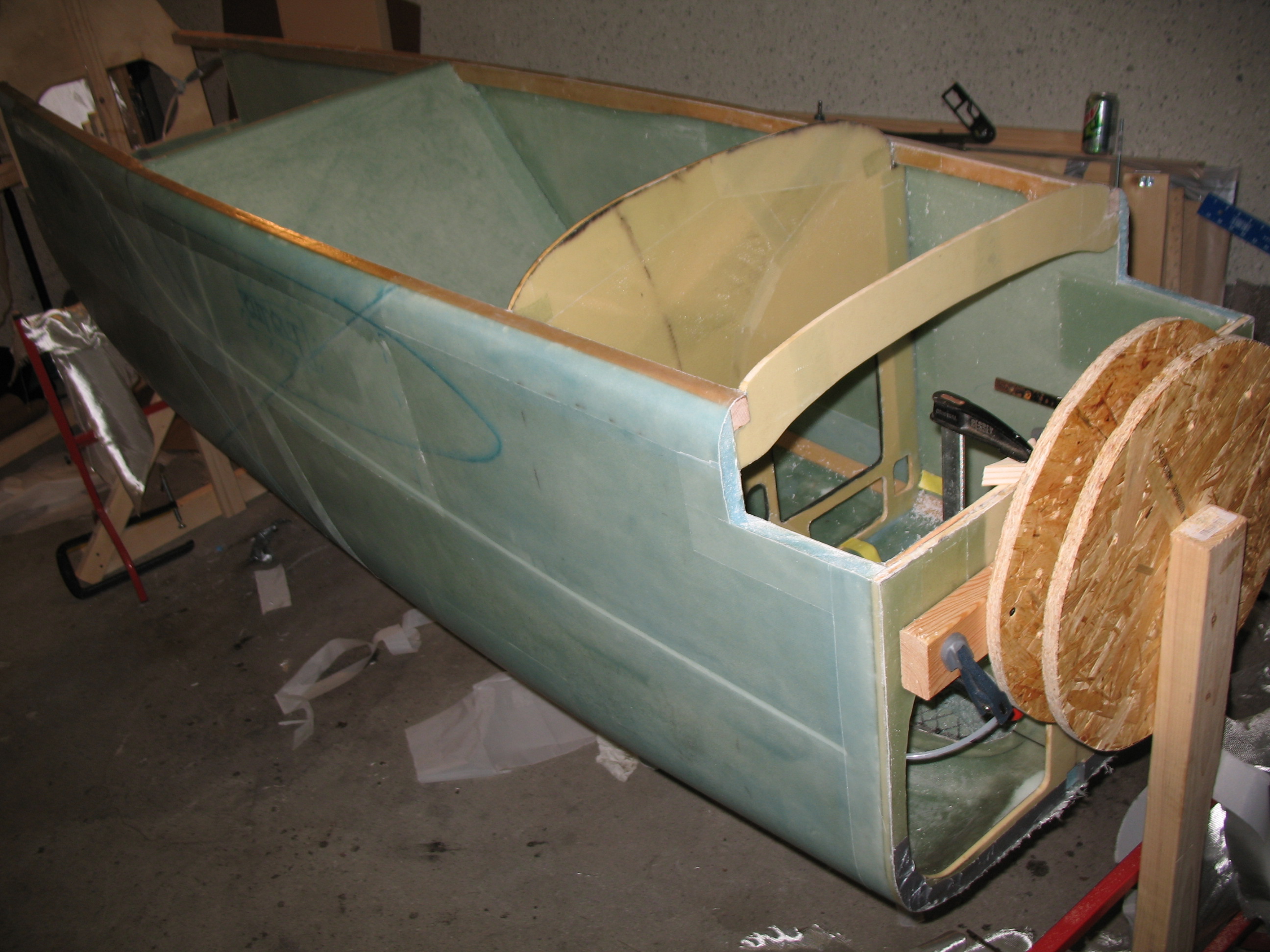
The outside of the seatbelt brackets, under glass, came out very nicely. I’m very happy with my decision to install them first and glass afterwards, and keep from drilling holes through my freshly glassed fuselage skin!
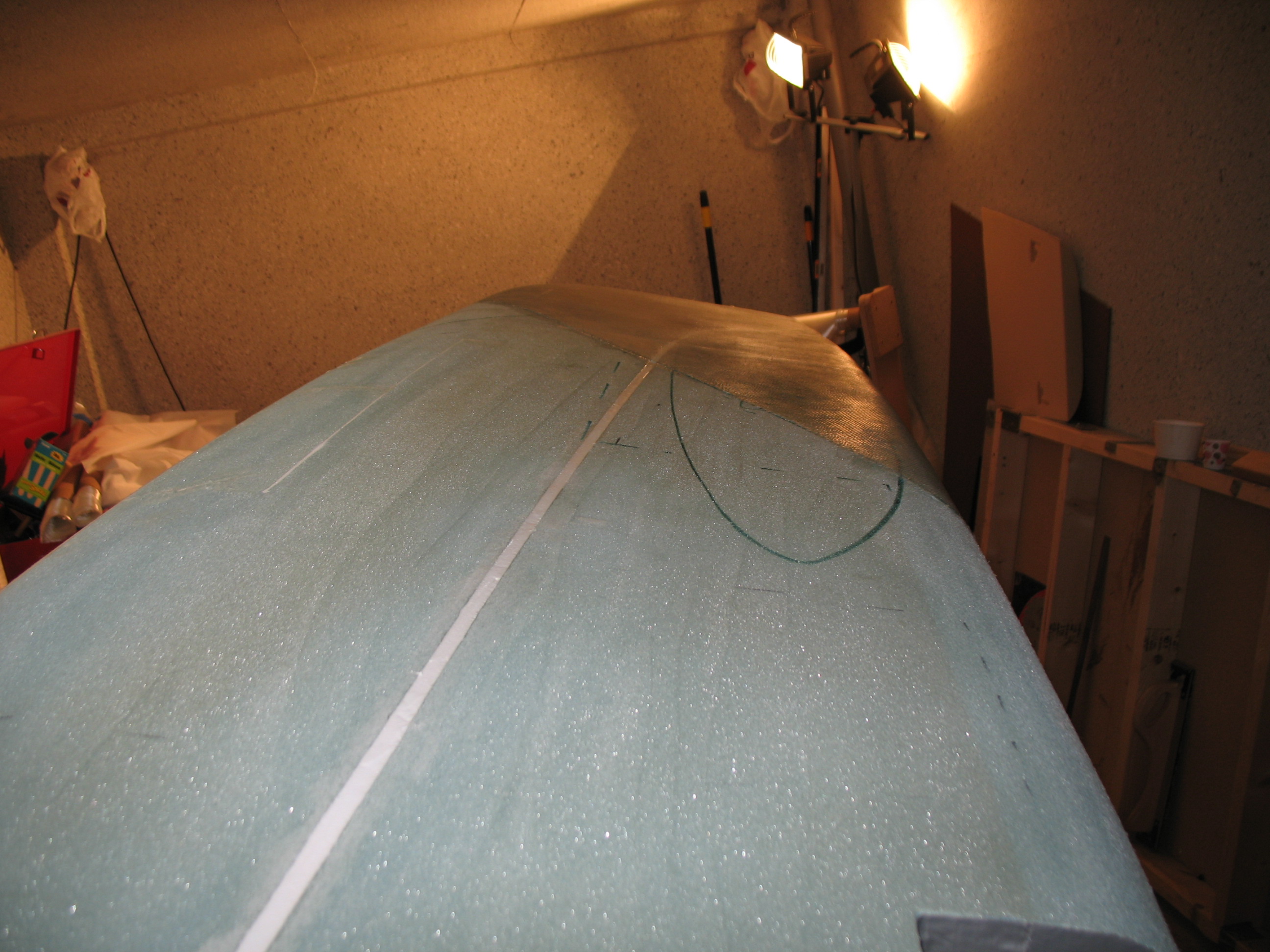
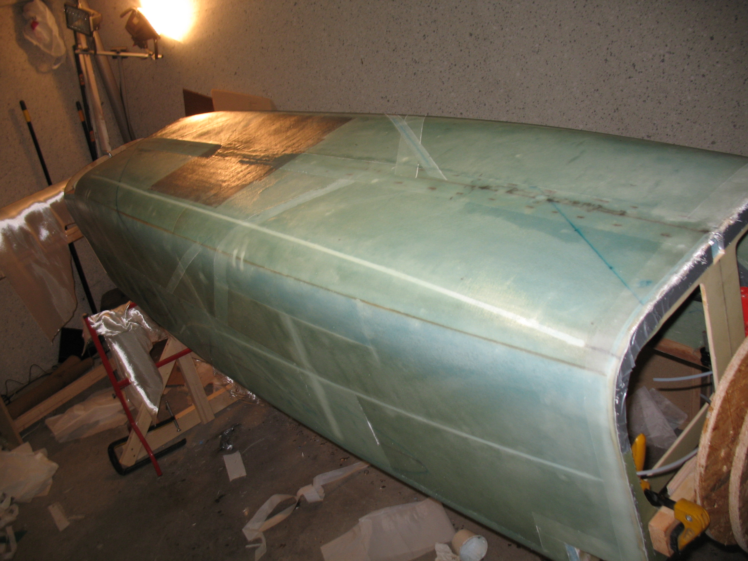
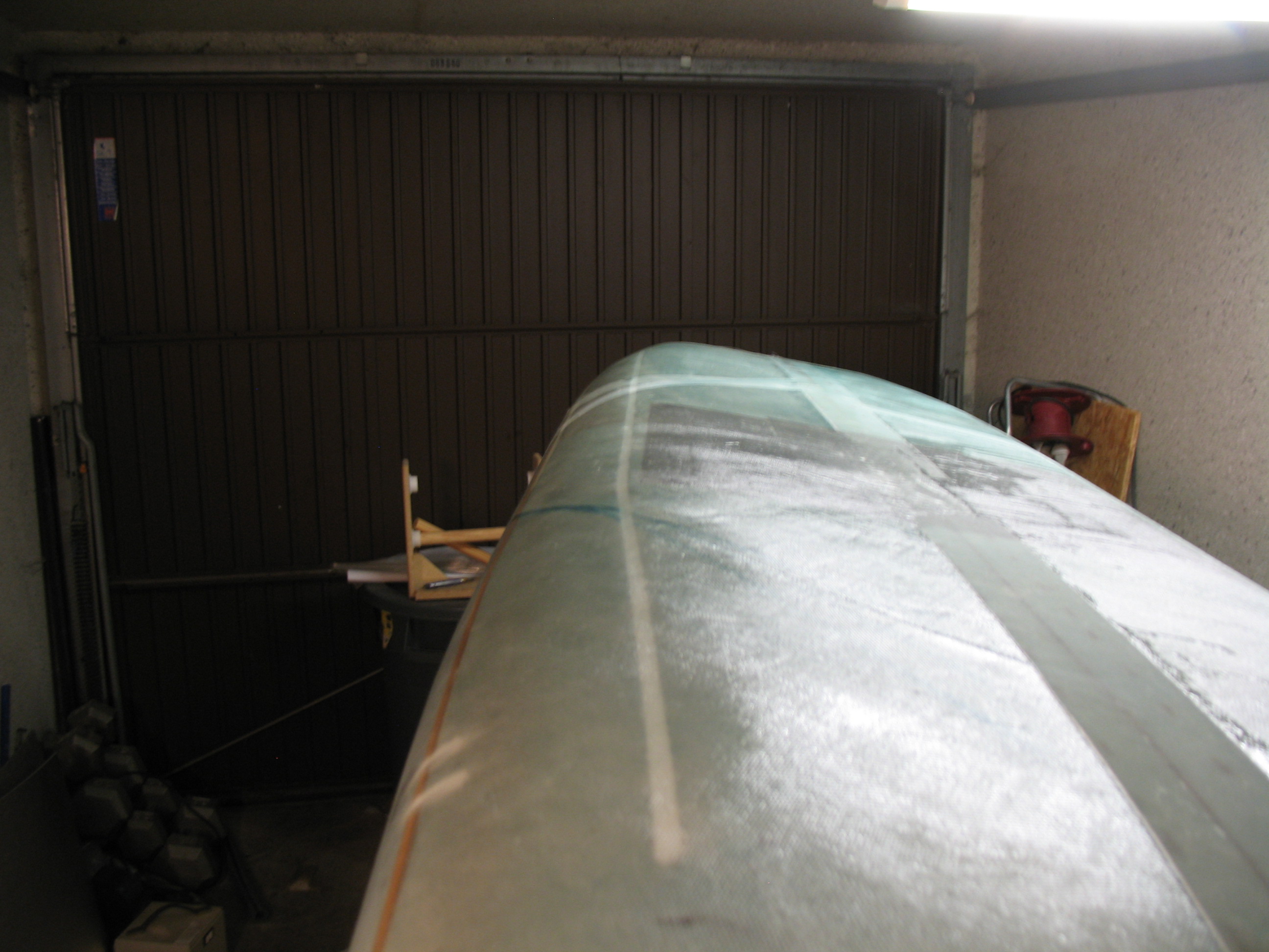
After I crashed for about 5 hours, I got up and checked the fuselage layup. Thank God I was using the ever-forgiving MGS 285 system! There were times where the bottom 30° UNI ply was getting fairly tacky by the time I laid up the opposite 30° UNI ply, but still took the next ply without balking. After a number of hours it all looked PDG! Definitely not perfect, and not an award-winning performance for certain, but the layups looked good, with enough epoxy that they don’t look starved at all, but not too much either… I think it’s a nice, strong fuselage!

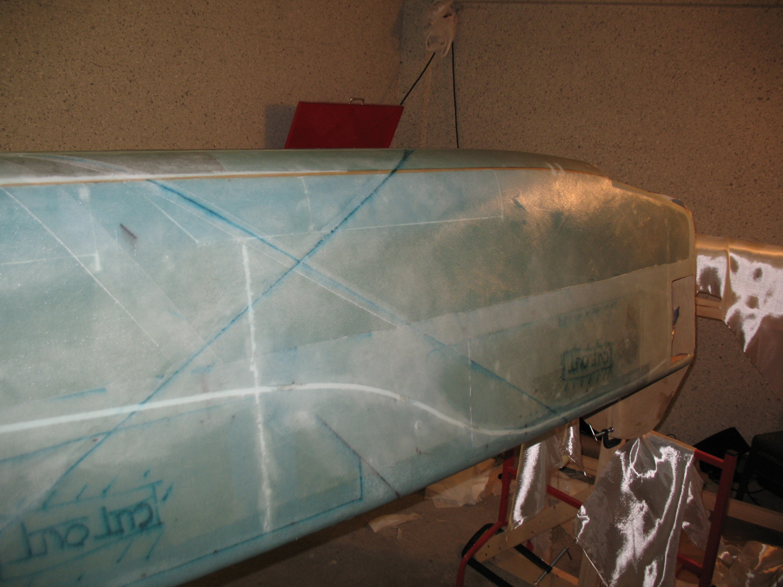
Late Saturday evening I pulled the peel ply, cleaned up some of the threads, and knifed trimmed a few more areas I had missed.
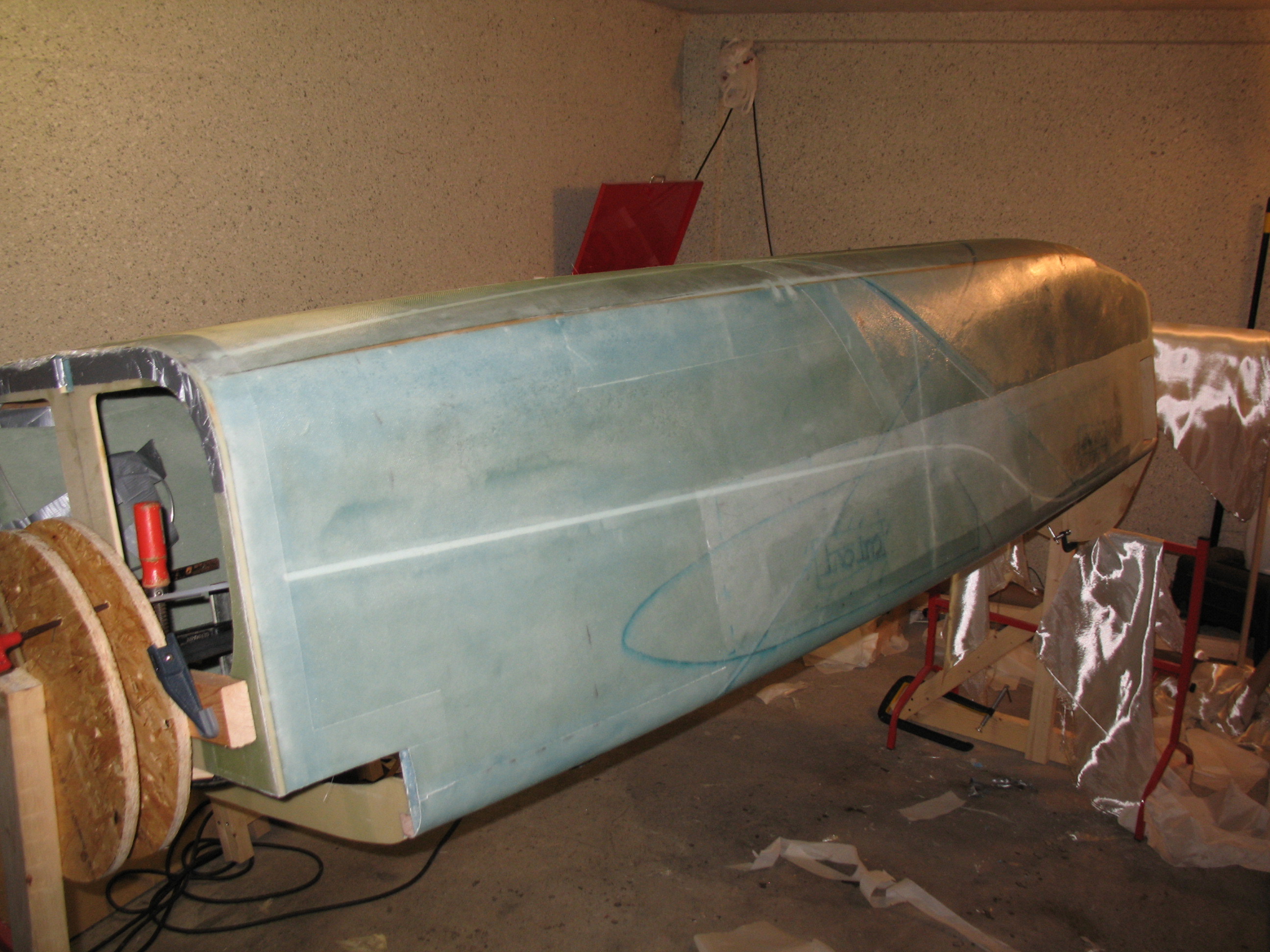
I poured myself a Jack & diet, fired up a cigar . . . and then sat back and enjoyed the site of my freshly glassed fuselage!
•••
17 June 2012 – Today I started a massive multi-hour campaign to clean up “peel-ply snot” from the areas left from pulling up peel ply. Peel ply is great, but the raw carnage it leaves behind is something I think we plastic airplane builders forget over time. Anyway, with a fairly string-free fuselage I proceeded to prep for laying up the two sets of 3-ply 3″ UNI “tapes” (cut UNI cloth) along the top of each of the upper longerons.
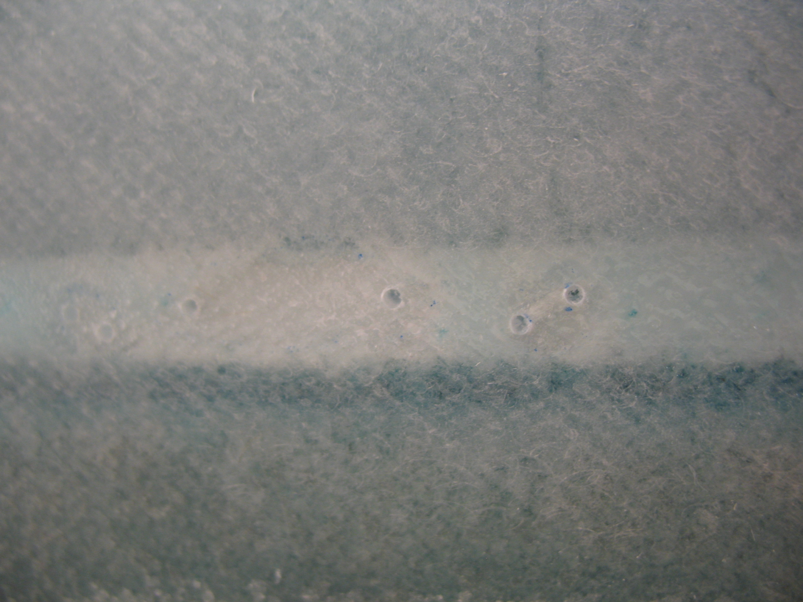
Before I could layup the UNI tape sets, I had to take care of few air bubbles that insidiously crept into my fuselage glassing layup, mainly over the upper conduit areas. I used a hand drill to make a couple of holes in the glass and syringed in some epoxy. They weren’t that large, maybe .2″ to .4″ at the most (oblong, not round) here and there, but since they were right under my UNI reinforcement tapes, I wanted as much strength as possible.
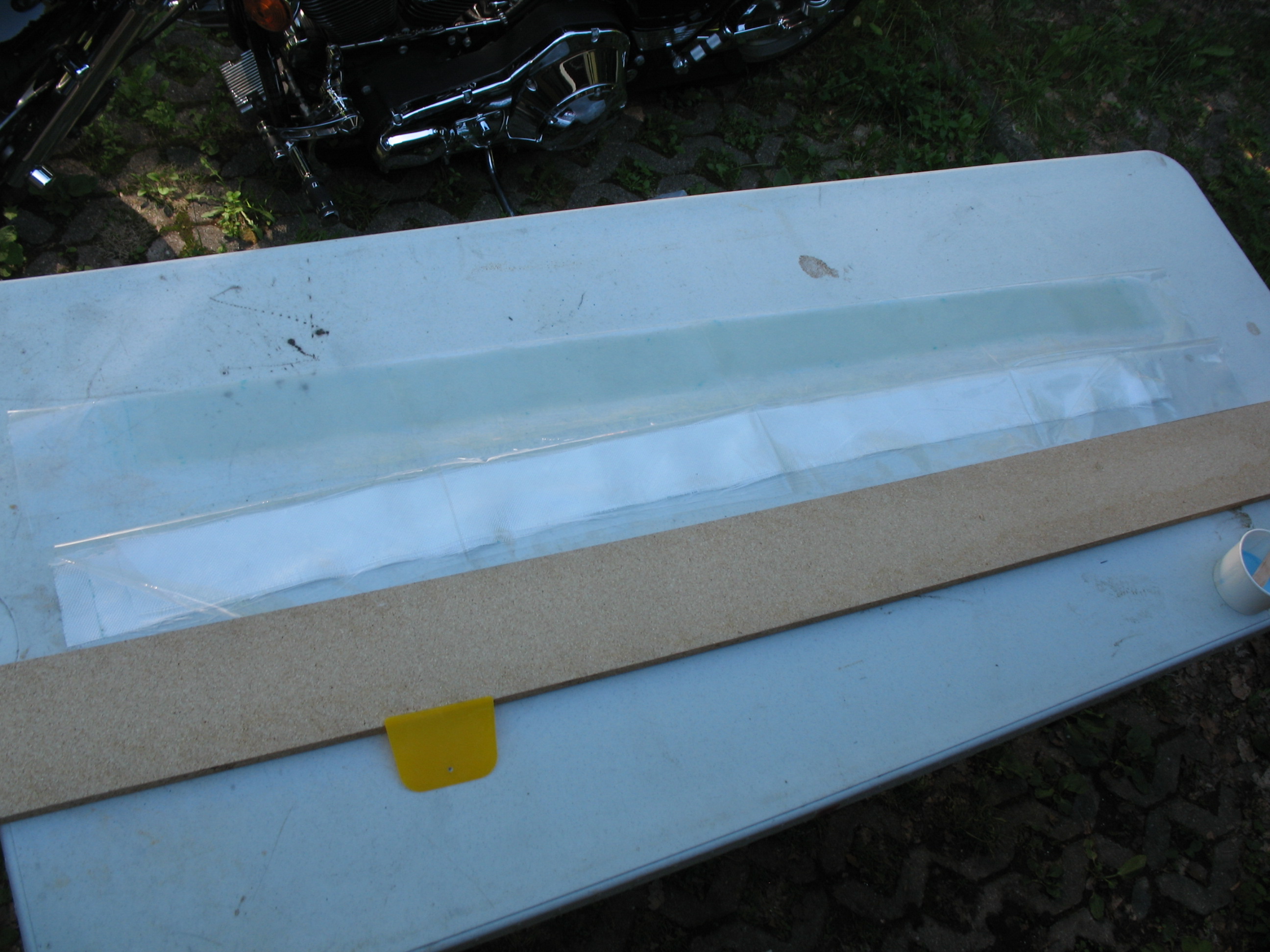
 After removing the offending air pockets with injected epoxy, I started prepping for my 3″ UNI reinforcement tapes layup. I set-up my portable table and got a length of scrap particle board to use as a base for my squeegeeing activities. I then grabbed my 3″ UNI tape prep-preg set-ups and went to town.

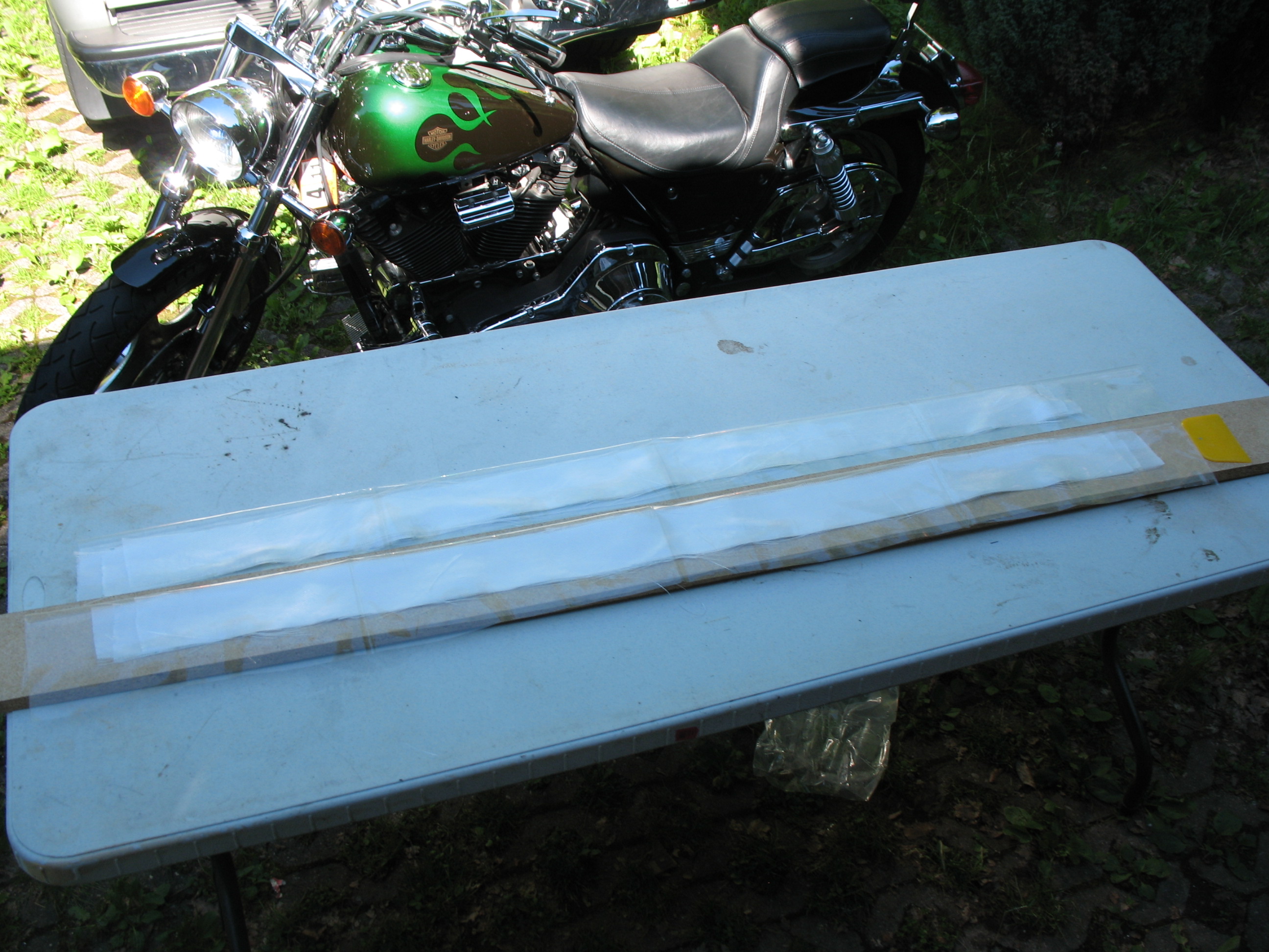
Remember, since I’m removing a little bit more fuselage side material for a longer strake opening on each side, I added 2″ to each end (4″ total) of the 3 UNI tapes for final lengths of 54″, 52″ and 50″. I wet out one set of the UNI pre-preg and laid it up on the Right longeron. Once I had the Right-side longeron layup good & peel-plied, I moved on to the Left longeron.
And so ends a very long step in the completion of this airplane … and I’m just happy to be able to state:
Chapter 7 – Fuselage Exterior is complete!!!
•••
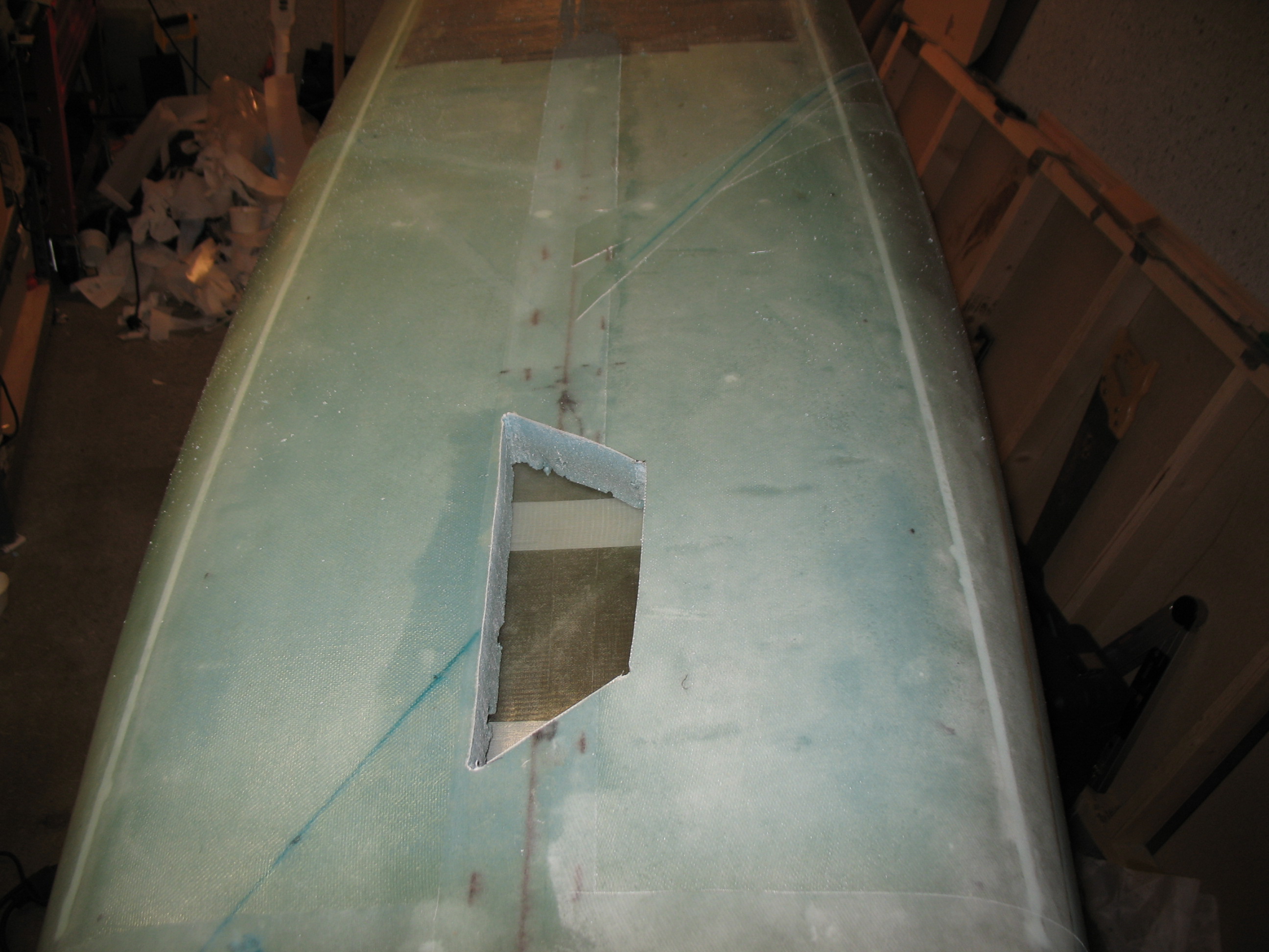
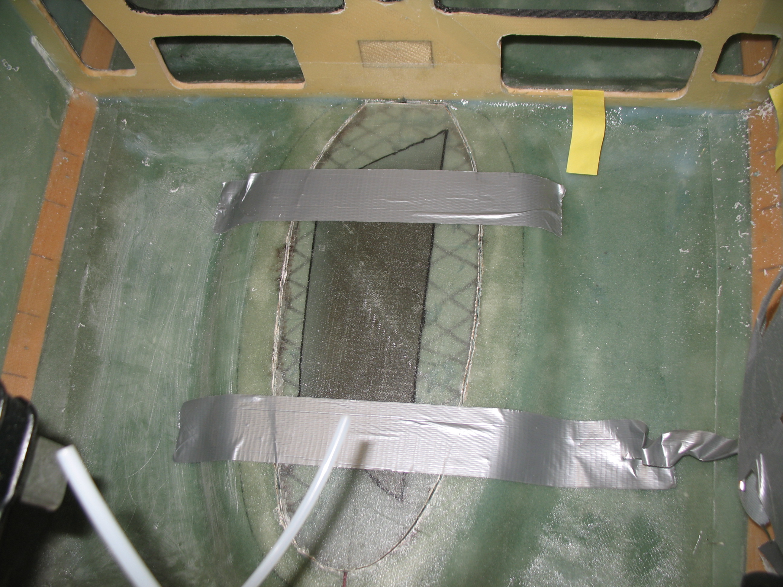
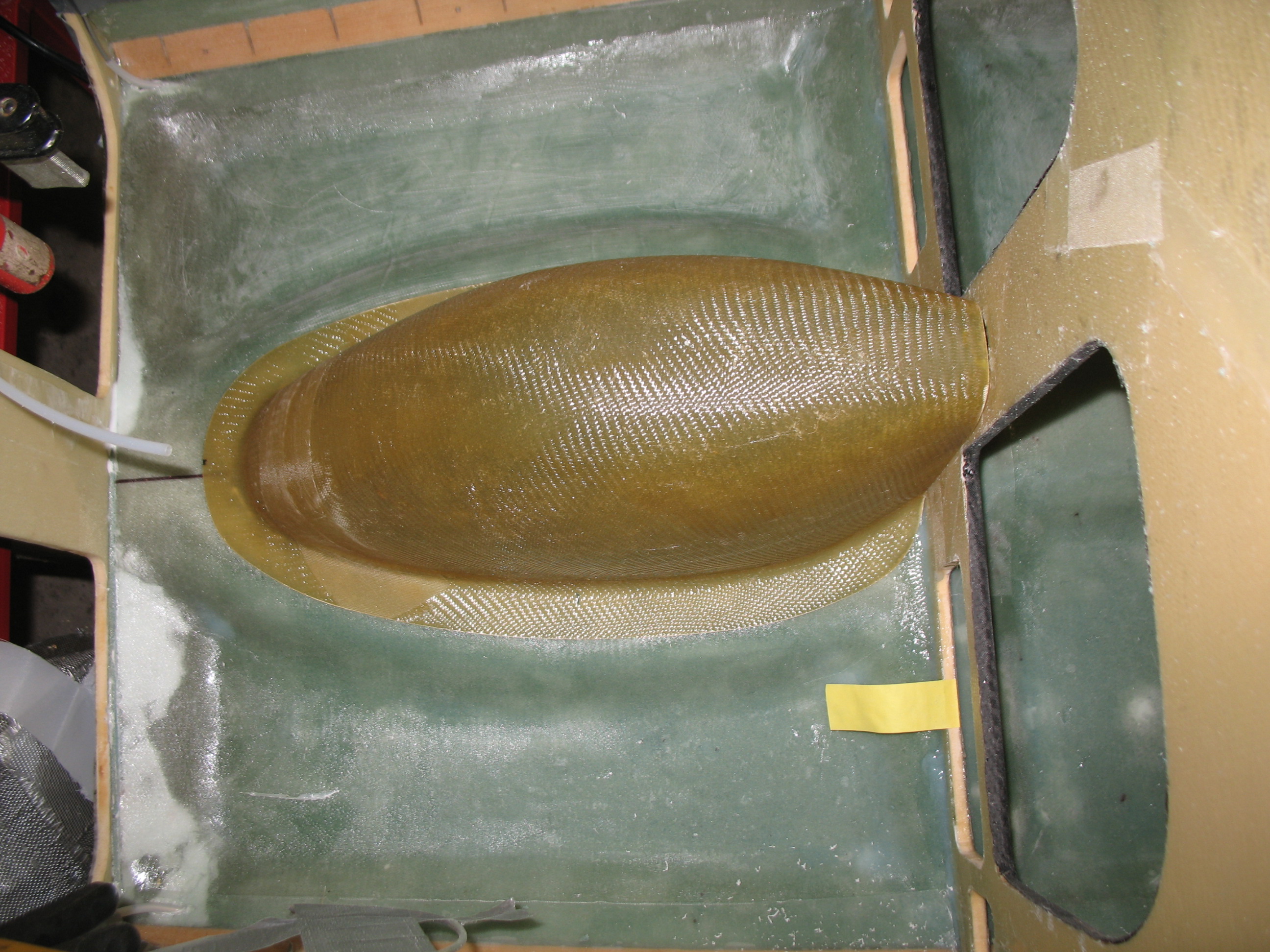
18 June 2012 – I finished up Chapter 7 (technically Chapter 6… but who’s counting??) by cutting out the nose gear well. I started by cutting a non-symmetrical shape from the inside, since I could see the actual shape outline and then grabbed the original fiberglass nose gear hole cutout from when I Dremelled it out earlier (that was after I mounted the fuselage bottom to the sides). After I cut the weird-shaped nose gear hole through the bottom of the fuselage, I set the cutout fiberglass piece back into place and taped it. Once it was securely in place and back in its original spot, I traced the shape of the newly cut hole.
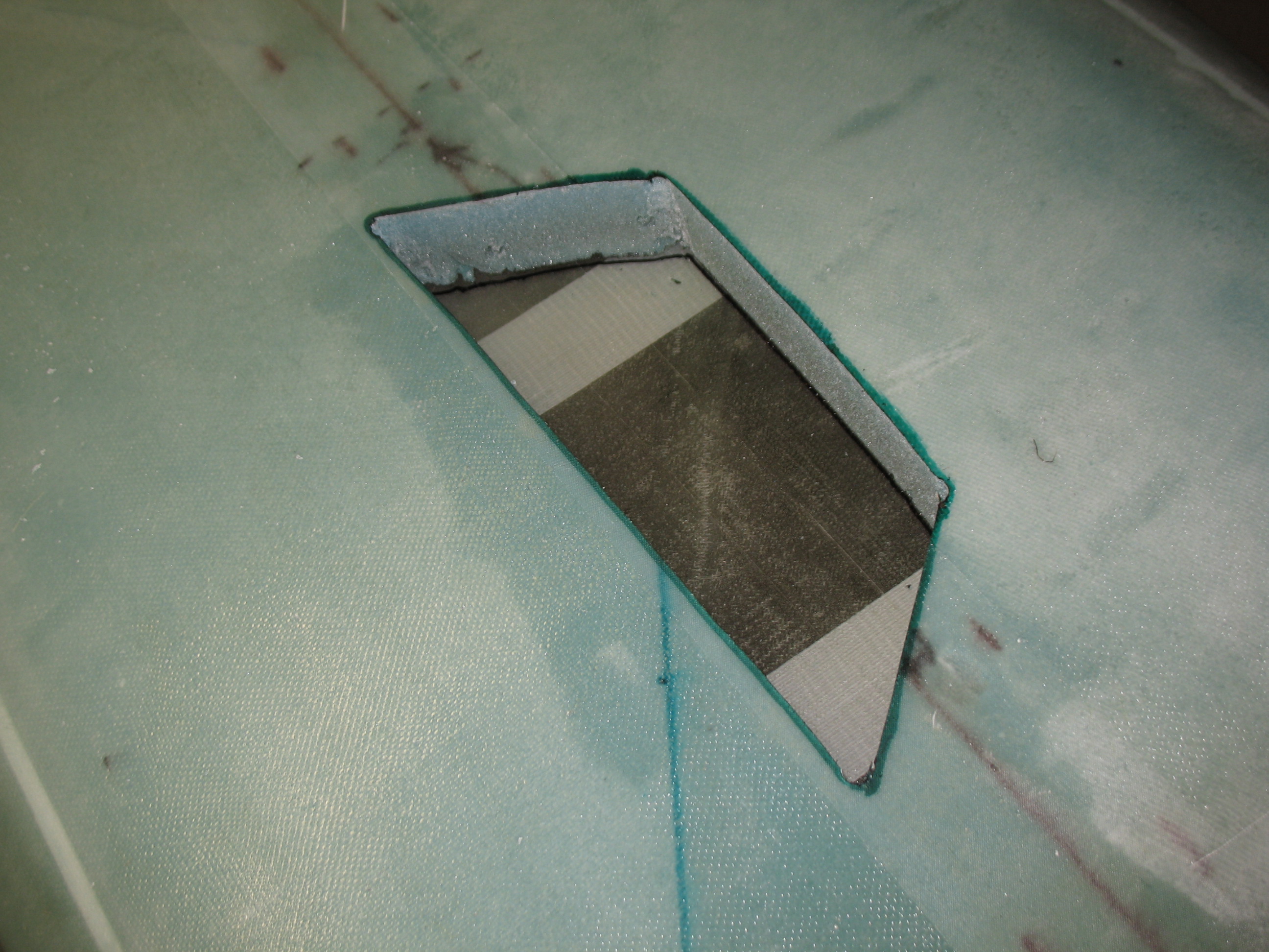
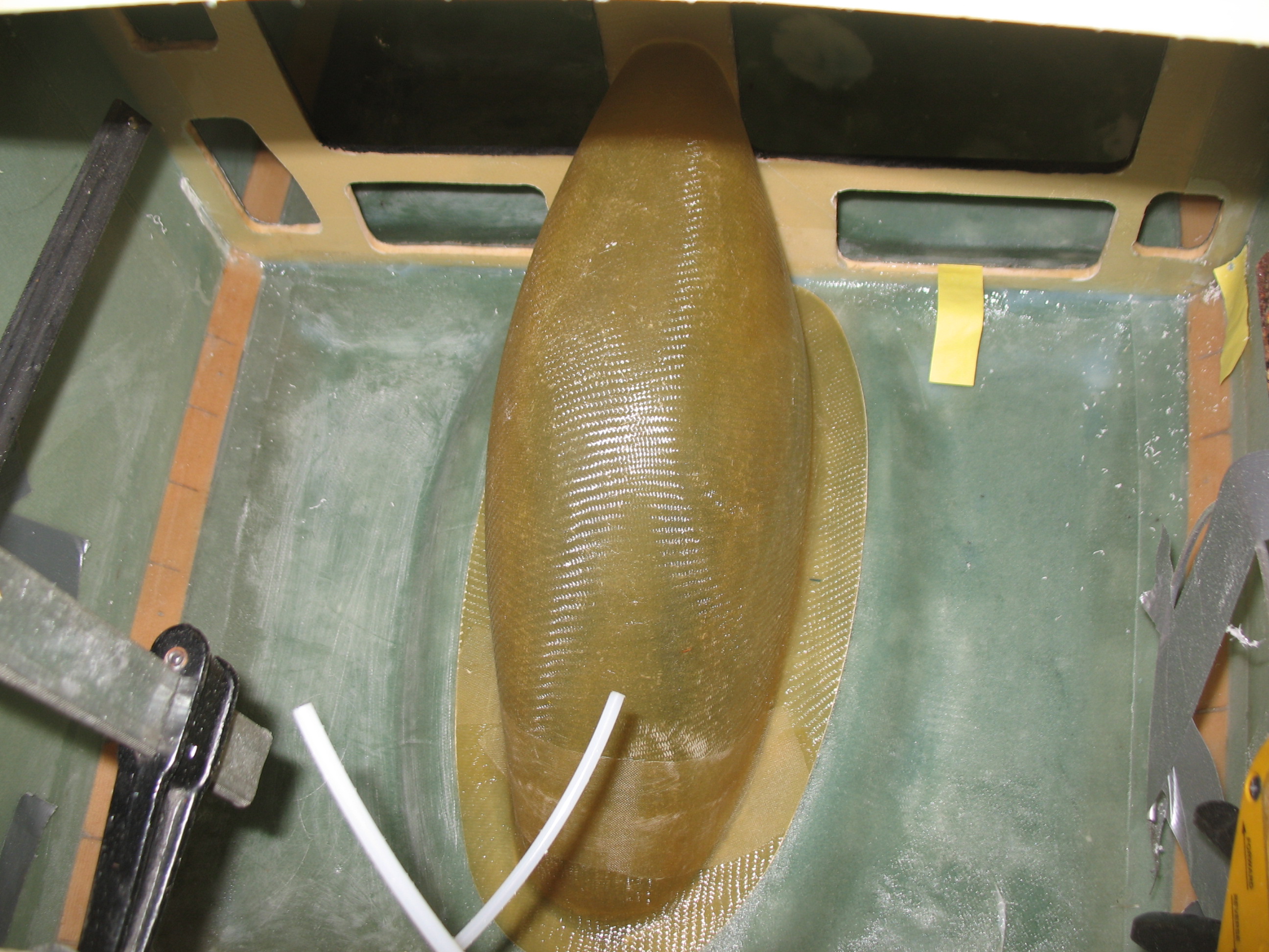
 Once I had traced the outline of the hole, I removed the fiberglass cutout piece and moved it to the outside of fuselage to transfer the shape of the landing gear hole. Once I transferred the nose gear hole outline, I simply grabbed the jig saw and cut out the front nose gear hole.
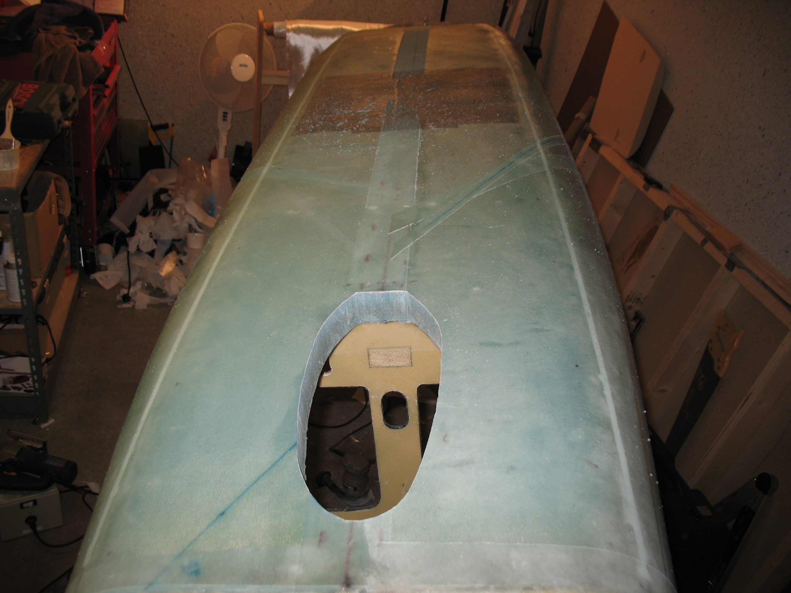
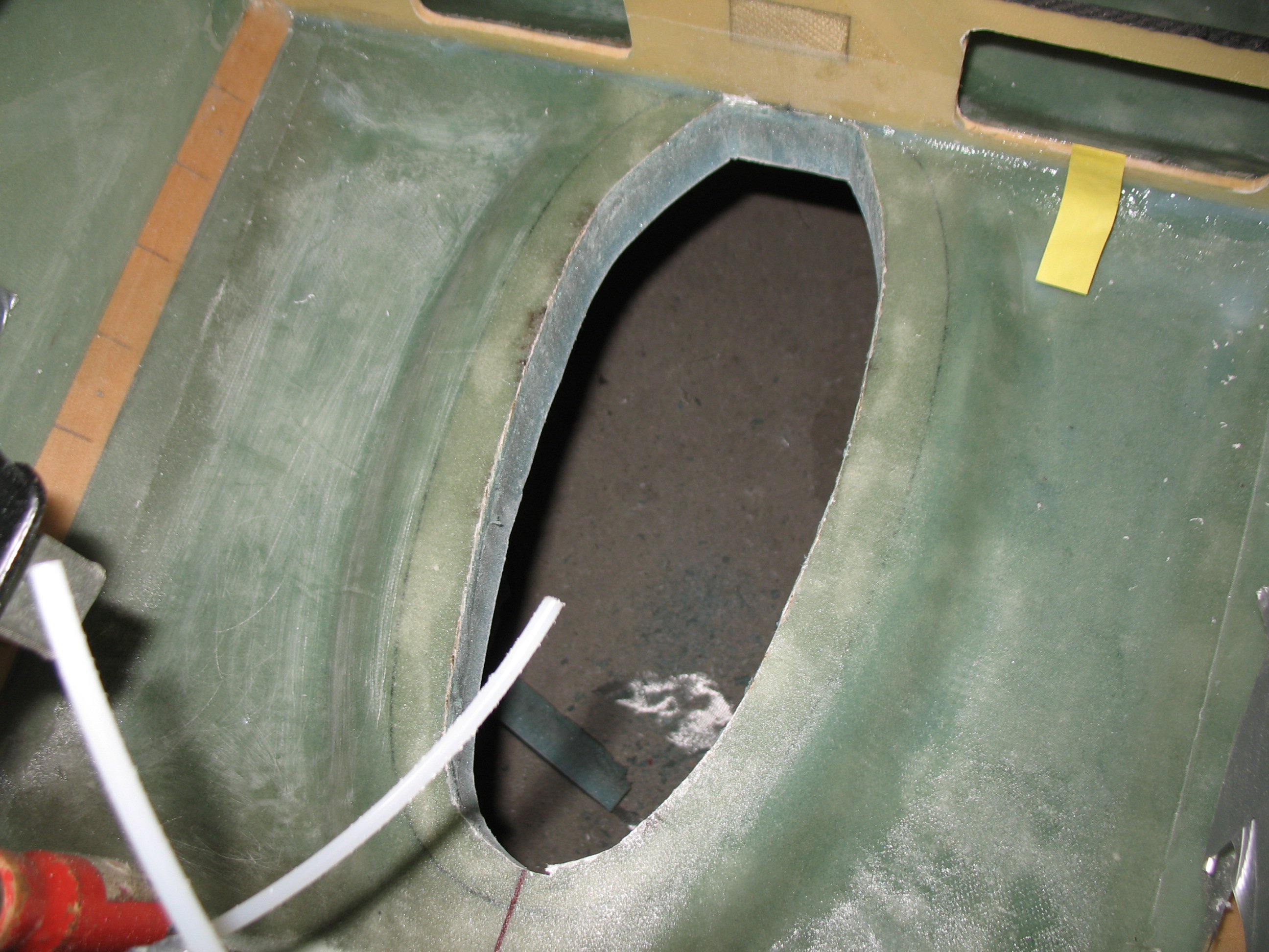
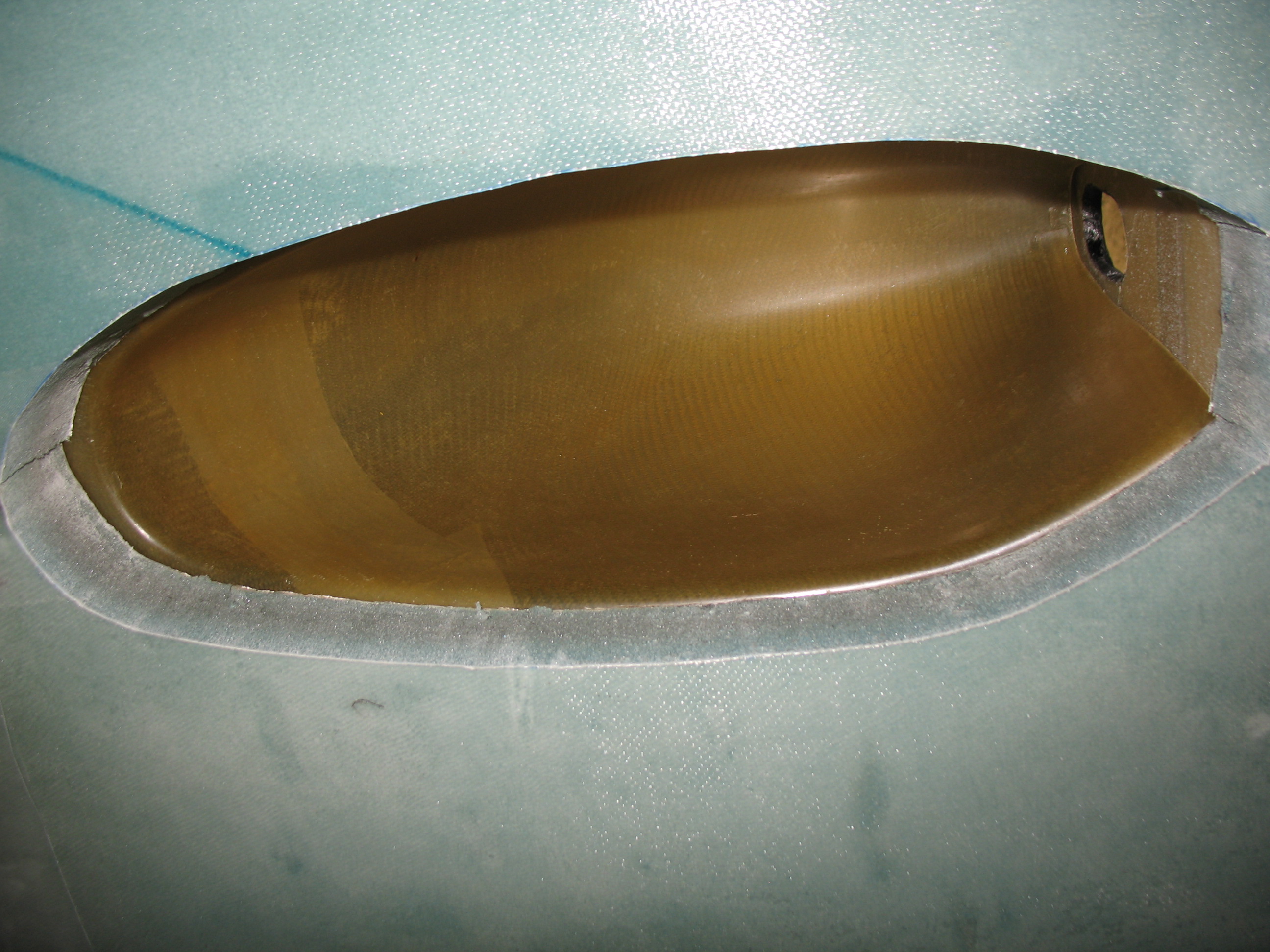
If the nose gear hole looks a little non-symmetrical and uneven, it’s because it is. Since the plans have you cut it to shape based off the nose gear cover (NB), which is a purchased part, there’s not much you can do since it comes that way! However, once the nose gear cover was set into place the lopsidedness of the hole was fairly obscured. And once gear wheel doors are built and set in place, the irregular hole will be virtually invisible.
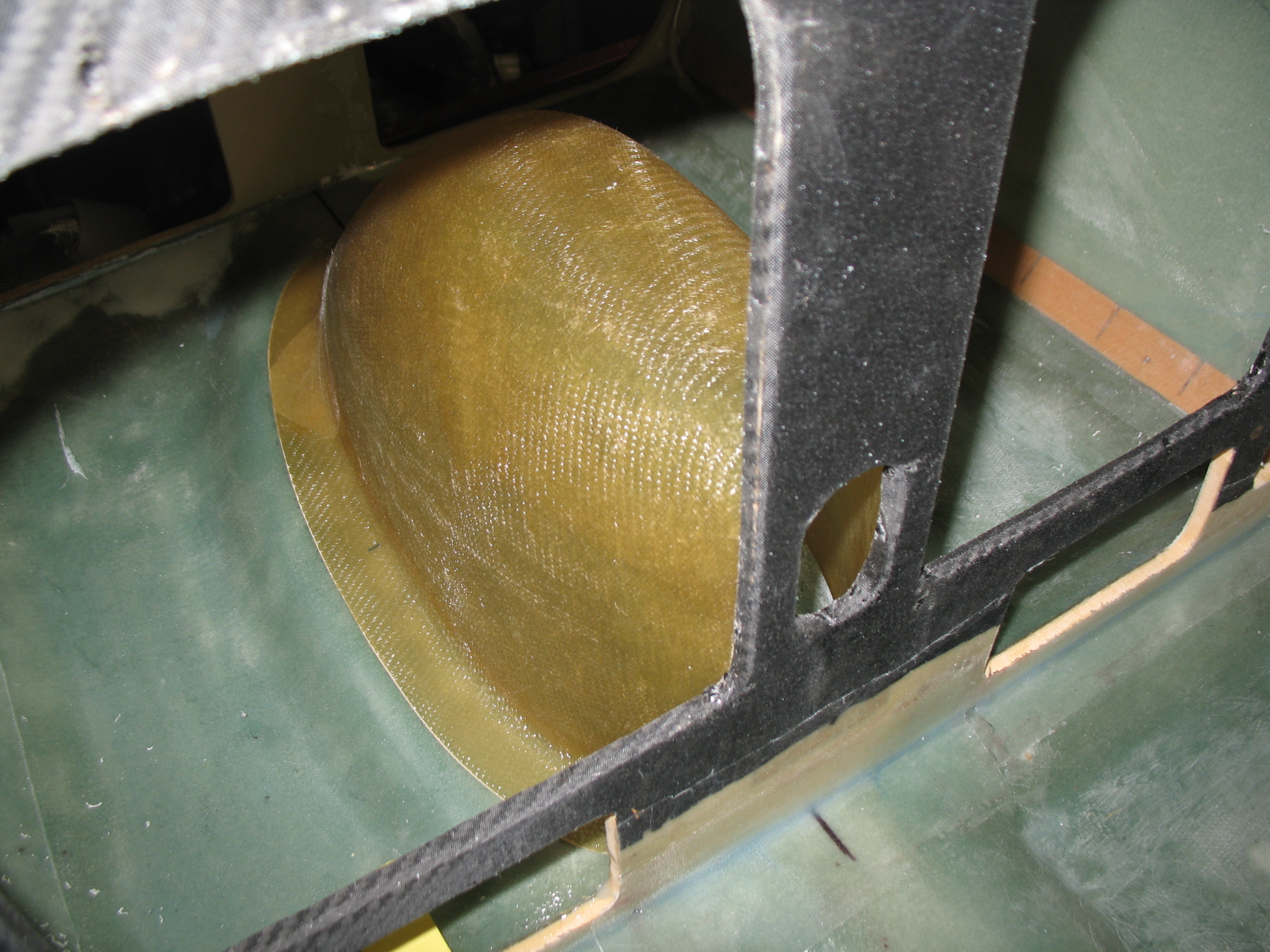
I chose to hold off on installing the nose wheel cover (NB) as the plans would have you do it here, but instead installed at the tail end of the initial nose build and nose gear installation, so it’s covered in Chapter 13.
•••