
Chapter 23 – Engine Build: Part 3
(This page covers the engine post major build after I brought it back to my shop)
2 March 2018 — Since I brought the engine back home to my shop, I’ve been doing a fair bit of mock engine component installs and taking note of what I’ll need on hand to finish the engine installation when the time comes.
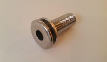
One such subject item are the firewall pass thrus. As I reported last week, I picked up a 1/2″ ID stainless steel firewall pass thru and liked the concept so much I ordered another 2 of them to finish off my acquisition tasks for purchasing firewall pass thrus.
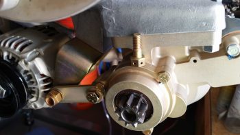
After a test install of the alternator and starter, I was also able to measure and then order the appropriate alternator-to-starter support link (1.794″ version) from B&C Avionics.

I also identified a myriad number of hardware/fitting pieces that will need to be on hand to install the starter, fuel lines, exhaust pipes, etc. Although I did identify a bunch of these items, I have not yet ordered them as I am building an order currently on ACS.
•••
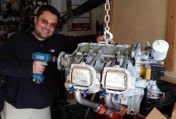
8 March 2018 — Today Marco pulled a surprise engine inspection on me so I HAD to stop what I was doing so he could critique the engine, and everything else I was doing! ha! Actually he had training at Dulles, so he stopped by for just a few minutes, checked out the panel and the engine quickly before we headed off to a quick lunch at the Peruvian chicken joint just down the road. Then off he went back to Chesapeake and I got busy loading up the trailer again.
When we returned from lunch my ACS order had been delivered with the box sitting on the front porch. The order included the somewhat pricey Lycoming bolt for the starter. Also note the B&C alternator-to-starter support link test install.
And the replacement crankcase vent fitting with the 5/8″ barb to fit the SlimeFighter oil-water vapor unit that I’ll be testing out . . . at a minimum I simply need a fitting to attach a 5/8″ hose to.
•••
16 March 2018 — Over the last week I researched flywheels to enable me to pick the best one for my configuration. To back up just a bit on this story, my initial flywheel conversation during my engine build with Wayne Blackler, Sky Dynamics, Power Sport and ECi (Continental) convinced me to NOT go with Sky Dynamics’ lightweight flywheel, which was my initial flywheel selection.
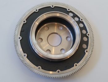
Over the past few days I spoke with B&C about 7.5″ vs. 9.75″ alternator pulley wheel diameters with them stating that there’s a negligible difference at low RPMs and no difference at normal operating RPMs. I then again spoke with Sky Dynamics and then Sam from Saber Manufacturing (super informative) regarding my flywheel selection. I did a bit more research then was ready to pull the trigger. I talked to a couple of aircraft parts places, and narrowed down my selection to 2 possible flywheels: one in Nevada and one in Florida. Air-Tec, Inc. in Florida won out since they had a new -360 flywheel (I have to use a 360 flywheel due to my 1/2″ prop flange bolts) with a 7.5″ diameter alternator pulley wheel and 149-tooth starter ring, so I pulled the trigger.
It arrived today and it really is a beautiful hunk of metal.
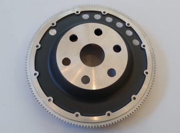
I chose to use the 7.5″ diameter pulley wheel since it reduces the flywheel weight by about a pound. A standard 320/360 flywheel with a 9.75″ pulley wheel weighs 6.3 to 6.8 lbs, and my flywheel weighs in at 5.72 lbs. To be clear, my flywheel is NOT the lightweight flywheel that Sky Dynamics sells, which has a total weight of 4.1 lbs. For me, the bottom line is that I am really happy with this flywheel!
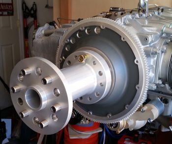
 I wanted to ensure all the parts actually fit, so I test fitted the flywheel on the engine prop flange, then checked the fit of the 8″ prop extension. Admittedly, I called Sam at Saber Manufacturing a couple times today just to ensure I wasn’t mucking anything up, specifically since the prop extension is machined to have as just about as tight as fit as possible on the center 1/2″ cylindrical extrusion of the prop flange.
With the engine hanging off a chain and thus not stationary, I couldn’t really manipulate the prop extension to get it to seat fully on the flywheel. Moreover, I need to install a shorter alternator belt than the one I received with the alternator (knowing that 9-3/4″ dia. pulley flywheels are way more prevalent than the 7.5″ pulley flywheels, I denoted that on my original alternator order…) so I definitely don’t need to experience the pain of working on the incredibly tight-fitting prop extension twice if I can just do it once.
The bottom line here is that I now know that all my major engine parts play well together and that the only outstanding engine part I currently need is a shorter alternator belt.
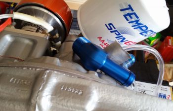
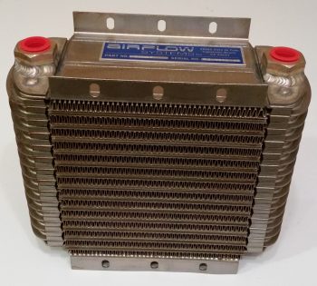
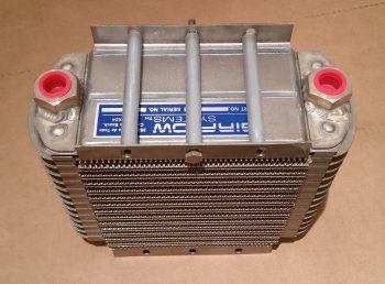
Speaking of engine components, I also received the Airflow Systems 2006X 13-row oil cooler that replaces the much too big 17-row 2008X model. I had expected that might be the case even when I ordered the 2008X, thus why I never opened the box. But again, having finalized my decision on the oil cooler model size, I quickly opened this sucker up to check it out.
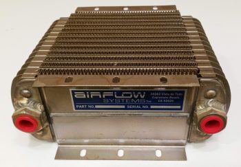
Except for one minor bend on one of the mounting flanges, it looks like a really nice unit. Moreover, I think it’s a great compromise between performance and weight/size.
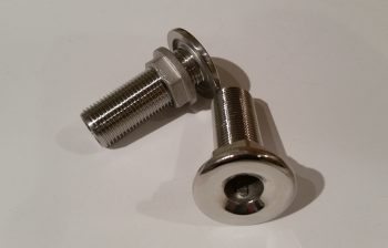
Today I also received 2 more possible stainless steel firewall pass-thrus. These are the same size (1/2″ ID) as the one I picked up for running the CHT & EGT wires through the firewall from the GRT EIS4000. I’ll test & eval this pair of firewall pass-thrus to use for traversing the throttle and mixture cables through the firewall, without having them attached to the firewall. In addition, just as with the previous one I picked up for the CHT/EGT wires, at least 2/3rds of the threaded part will be removed to reduce the weight significantly.
In a discussion I had with my engine builder, Tom Schweitz, towards the tail end of the engine build, he was adamant that I install a sniffle valve since I have a horizontal induction engine. So I undertook a significant research campaign to determine if I needed one or not.
The result of my research is that a horizontally induction engine owner will most likely never need a sniffle valve, but if a scenario ever played out where a sniffle valve was needed (pooling of fuel OR water in the cold air induction plenum), then the resulting effects of NOT having one could simply be catastrophic to an engine (kickback, etc.).
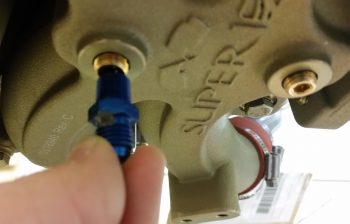
Thus, for a $25 sniffle valve from Airflow Performance, I figured I would have a nice little insurance policy in my back pocket against any untoward fuel or water flooding events in the induction plenum.

Superior actually makes two ports for sniffle valves on the bottom of their induction plenum (one might possibly be for a MAP-style fitting as well).
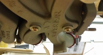
Since we park our EZs in the nose-down grazing position, and my engine is backwards (aren’t all of ours?) in regards to the cold air induction plenum, I will be mounting my sniffle valve in the forward of the 2 supplied ports on the underside of the plenum.
•••
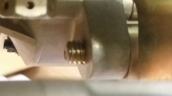
17 March 2018 — I started off today by going down to my local Village Hardware store to see if they had a #8 “aircraft grade” 1-1/4″ x 5/16-18 bolt on hand. This little hardware store rarely disappoints and they continued their tradition today. The 1″ bolt I had in place for mounting the alternator-to-starter support link was just a tad short and I wanted to keep with showing the requisite 2 threads on any given mounted bolt. As you can see, the 1-1/4″ bolt does the trick.
[If you’re wondering why I went with a #8 grade bolt here, try finding course threaded 5/16″ bolts on Aircraft Spruce, Wicks, etc. If you do, they are most likely very expensive and for a very specific purpose, such as my Lycoming starter mounting bolt].
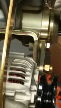
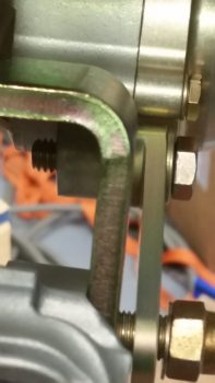
As visible in the pics above, I already have one washer in place, and with either an added lock washer or a set of Nord-Locks there will still be visible threads.
As I was returning home from NC I stopped off to check my mail and noticed my driver’s side headlight was out. I had bought my other headlight at Advanced Auto Parts, and coincidentally, this auto parts chain just bought out CarQuest, the maker of the belts that B&C sells for their alternators. Armed with that knowledge, when I went to buy a new headlight I queried the folks at Advance Auto Parts about ordering a couple new shorter alternator belts (again, since I now have a 7.5″ diameter flywheel pulley). For some reason their system wouldn’t let me backorder the belts, so when I got home I tried online. No joy.
After spending another half hour looking for these darn alternator belts, I punted and decided to simply order them from B&C. In an effort to consolidate, be efficient and have no wasted motion on my B&C order, I decided to finalize my requirements for the engine grounding strap and order it concurrently with the shorter alternator belts (primary + spare) . . . but how long did the grounding strap need to be? And what size mounting bolt holes on each end?
I spent a few hours researching the best location for the engine ground. Yes, there is a nice factory provided threaded hole on the left side of the engine casing, but since my firewall ground post and starter are on the right side, I am attempting to keep the engine ground strap on the right half engine crankcase if possible. Finding a spot to mount the engine ground strap also required spending well over an hour digging into my baffling requirements, since I am attempting as best possible to stay clear of any baffle mounting holes. Again, since both the starter and the firewall grounding lug is on the right side, I also wanted my engine grounding point location to be on the right side engine case for the cleanest electrical path.
After assessing what other builders had done, getting a decent layout of how the baffles would get mounted, and having a general targeted area of where I wanted to mount the engine grounding strap, I then mocked up my engine mount onto the firewall (lying horizontally) to get a decent swag as to the required length of the engine ground strap.
My original goal for the engine ground strap was to get it as close as possible to the starter, but besides mandating a much longer ground strap (weight), the best mounting positions for a ground strap are holes that will be used for attaching the baffles to the engine. I decided that if I have a good location on the forward right engine case (next to the accessory case but still right engine half) that the electrons will still easily be able to make their way through about 16″ of good steel. If not, I’ll readdress as required.
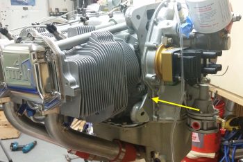
After scouring the right side of the engine for a good spot to mount the grounding strap, I finally decided on the location (yellow arrow above). I then extrapolated the required grounding strap length and double checked it with my engine mount on firewall mockup. The resulting strap length, with some room for maneuvering through the maze of hoses, etc. and generally slack for anti-vibration purposes came out to 13″, with a 5/16″ mounting hole on each end.
Thus, my final act of the evening was doing what I do best on this build: spend money! I pulled the trigger on two 7312 XL alternator belts (again, primary and spare) and 13″ engine grounding strap.
As of this date that completes the inventory for all the required major engine components, minus the fire sleeved hoses. I’m sure a few bits of hardware and fittings etc. will be required, but I’ve closed out all engine component requirements that I am currently aware of.
•••
18 March 2018 — Today I took a hard look at my engine preservation steps. I’m not exactly sure what’s going on with my engine dehydrator. It’s definitely doing something because the “dilithium” crystals (desiccant) are turning pink, but the humidity sensor on my out air line keeps showing an internal relative humidity only about 5% less than ambient in the shop. An example for clarity, say the shop RH is 37%, than the air out of engine will be around 32-34%. Maybe the 40 gal fish tank air pump I’m using is not big enough and I need more air getting pushed through? Or the fact that this engine has gaping holes (albeit taped up) in it since it’s not all put together? Not sure.
I did rewicker the dry air to enter the engine via the oil filler neck and out the crankcase vent vs. the other way around. Also, I disconnected the out line that was going back into the air pump and instead of a closed system I’m trying a simple dry air in and then wetter air out to shop air. I’ll assess if this has any impact on reducing the internal moisture in the engine.
I then tried my hand at baking all the pink desiccant I had collected in a small plastic tub. I put it all on aluminum foil on a baking pan, fired up the oven to 240° F and cooked them for about 1.5 hours.
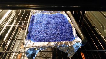
As you can see (although I guess a before pic would have been a good idea eh?) this baking thing really works and turns the quite pink desiccant crystals back to blue. It’s hard to capture the brilliant blue with a camera, but it’s a drastic difference. Pretty cool.

Although I have no doubt that my desiccant efforts is vastly helping keeping my engine internals dry-er, it doesn’t negate the fact that I need to get this engine pickled… and soon! Thus, weather be damned I’m going back into the shop.
I had 2 major issues regarding engine preservation that until this afternoon were unresolvable: 1) I need to be able to cycle through each cylinder to TDC and BDC for spraying preservation oil into the cylinders. Clearly I can’t do this with the engine dangling by a chain on a hoist. 2) I need to be able to rotate the entire engine upside down to bath the cam in oil/preservation juice. To solve both these issues –and be able to have the engine on-hand but stored in a smaller form factor– I bought an engine stand from Harbor Freight that will allow me to mount the engine to the stand so that I can handle the 2 issues that I mention above.

•••
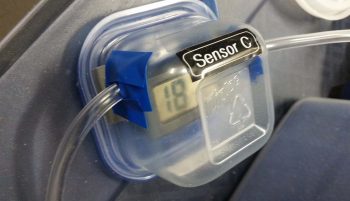
19 March 2018 — Today I was very pleased that with an ambient humidity reading of 36% in the shop . . .
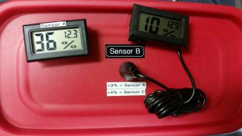
that my new engine dehydrator configuration yielded only 18% humidity internal to the engine! Now, that’s more like it! Anything under 30% is good and means minimal moisture in the engine, so obviously 18% is way better . . . that helps, but I still want to get this engine pickled soon.
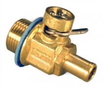
 I then called it a night for shop work and did a bit more research on installing & safety-wiring my Fumoto engine oil quick drain valve. I also did a quick inventory on some more engine fittings and hardware for my upcoming monthly (apparently) ACS order.
•••
1 April 2018 — Today I identified over 90% of my required components to roll my own fire-sleeved engine hoses (thanks Joe Coraggio for the tip on your website!). In fact, I pulled the trigger on the first of 3 major orders that I’ll be placing for the engine hoses.
•••
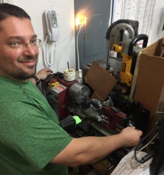
16 April 2018 — On my recent trip down to Chesapeake, Marco was gracious enough to do a bit of machining and lathed up some components for my build.
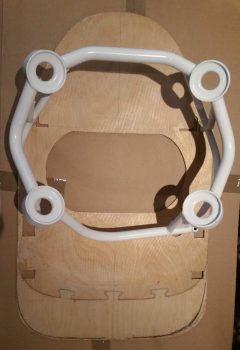
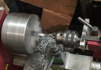
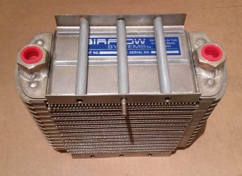
We cut two 1 foot lengths of 6061 3/8″ rods into 3 lengths that fit in-between the mounting tabs of my oil cooler.
Marco then used the lathe to drill out a 3/16″ hole down the center of each one of the oil cooler mounting spacers.
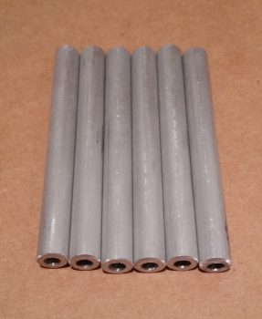
Here are the 6 oil cooler mounting spacers with holes drilled to accept AN3 sized mounting bolts.
Here are the top 3 oil cooler mounting spacers set in place, with the middle one mocked up with an AN3-41A mounting bolt.
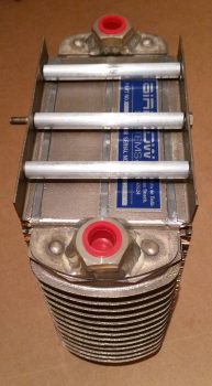
And here are another couple shots with the top 3 oil cooler mounting spacers in place with a test fit of an AN3-41A mounting bolt.
Of course Marco did an outstanding job on all the parts he machined/lathed for me (Thanks Brother!).
•••