
Chapter 17 – Pitch & Roll Trim Systems
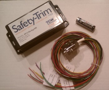
7 January 2013 — I ordered a fairly new-to-the-market 2-speed trim controller from TCW which was made specifically for heavier duty trim actuator motors (read: NOT Ray Allen servos!). Also nicely packaged and looks to be good quality. I had a few long discussions with the TCW bubbas about their different products, and these are some pretty smart guys!
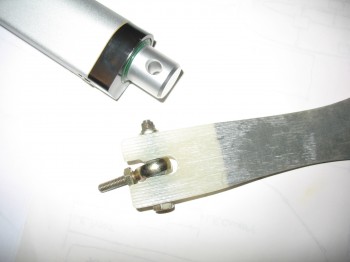
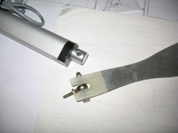
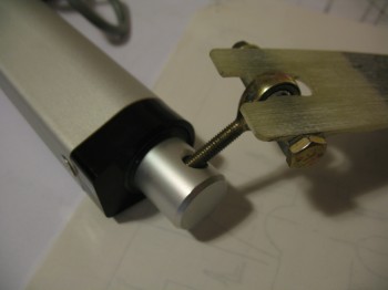
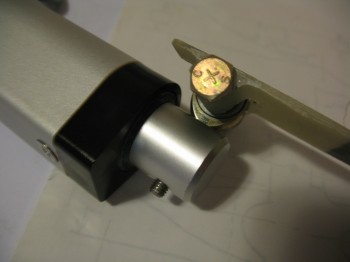
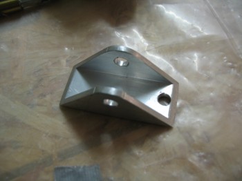
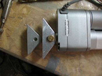
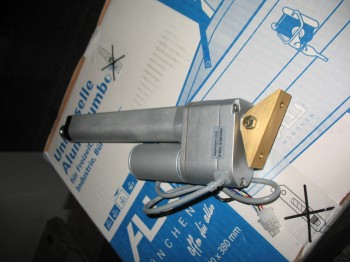
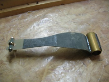
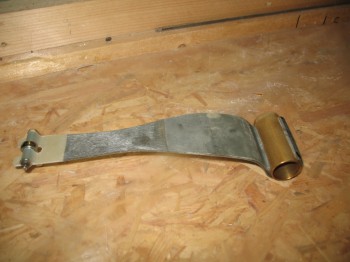
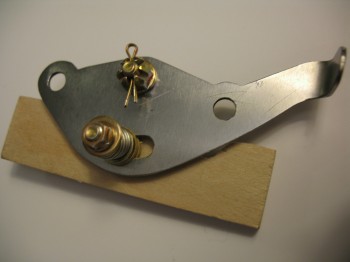
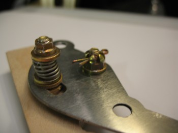
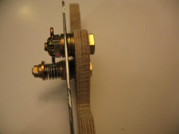
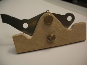
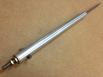
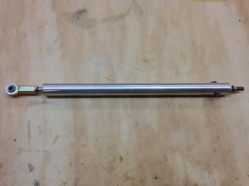
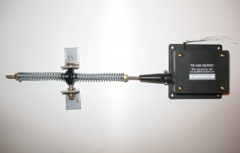
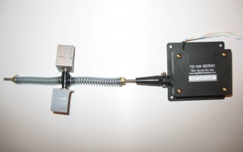
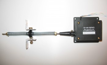
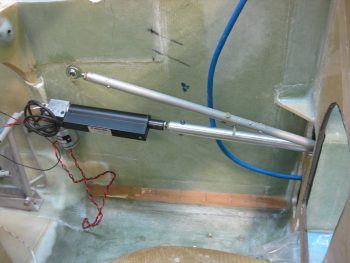
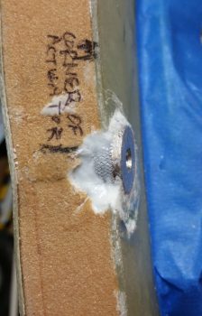
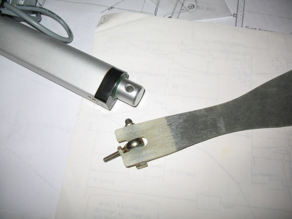
24 May 2013 — Daventport Leaf Spring Style pitch trim system from long-ez.com. The pics below show the actuator portion of the system.
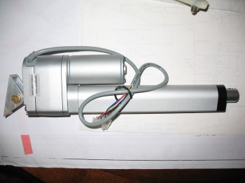
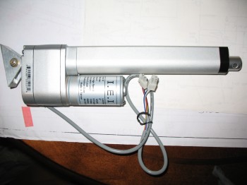
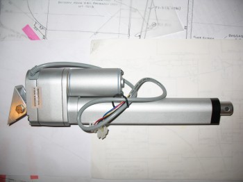
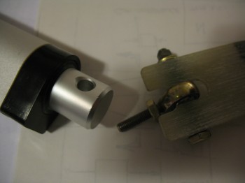
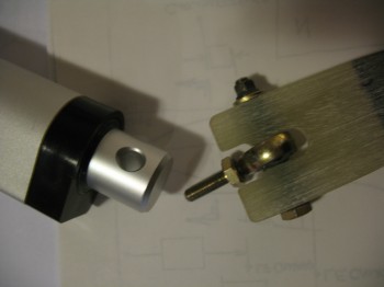
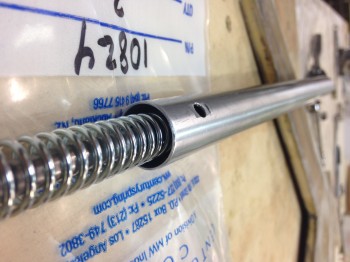
These pics below show the connection between the leaf spring that mounts on the elevator cross tube and the actuator.
•••
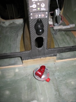
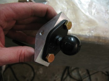
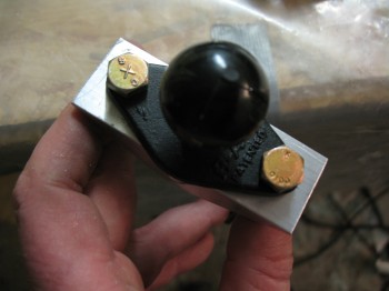
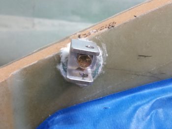
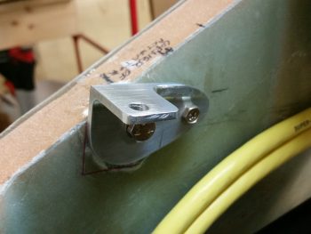
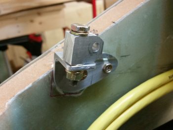
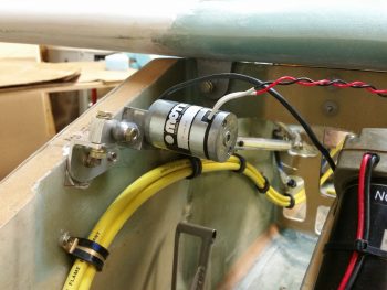
5 June 2013 — I grabbed the RAM ball mount that I had just received from Aircraft Spruce to mock it up where it will be mounted on the center instrument panel post. The bolts used to attach this RAM ball mount will also serve to attach the bracket on the pitch trim actuator for my Davenport pitch trim system (also shown in the picture below is my Andair fuel valve).
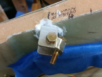
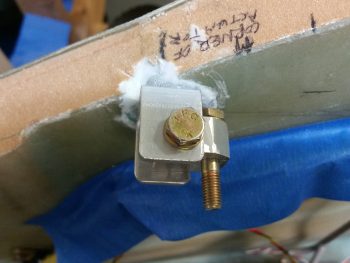
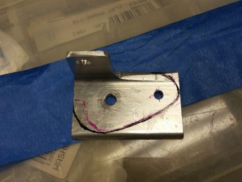
The screw used in the above picture is a AN3- (3/16″) vs an AN4- (1/4″) screw/bolt that will be used to attach the RAM mount & pitch trim actuator bracket. As I attempted to drill the 1/4″ holes on the original pitch trim actuator bracket I quickly noted that I had an issue with the bracket being too short.
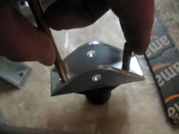
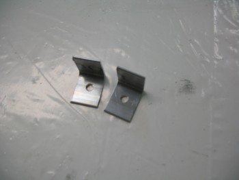
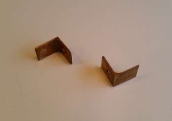
Although I got one hole drilled, and it looked like it could work, the hole wasn’t actually equidistant from the center meaning that the other hole would be even further from the center line, and actually into the angled edge. In short, I had to make another bracket to make this design work. So I cut another, slightly longer bracket out of 1″ x 1″ 2024 aluminum U-Channel.
I drilled the 1/4″ holes & test fitted the RAM ball mount.
Below is a comparison between the original bracket & the new one that I just made.
•••
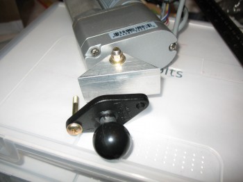
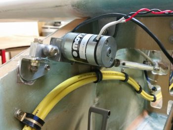
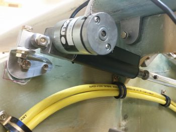
9 June 2013 — Here’s just a shot of my pitch trim actuator with its new & improved larger Alodined bracket shown attached.
•••
11 June 2013 — Today was a light build day.
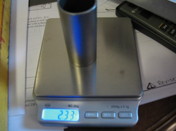
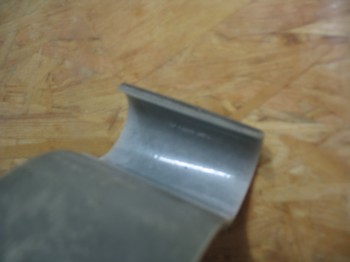
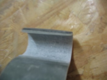
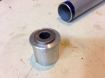
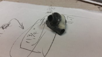
I Alodined a 2.7″ long x 1″ diameter tube that I just received from my buddy Marco. He was nice enough to cut & cross hatch this piece of 6061 aluminum for me as a replacement for a slightly corroded 4130 tube piece that had been attached to my Davenport leaf spring. This short tube slides over and is attached to the elevator torque cross tube, so when the pitch trim actuator arm extends or retracts it moves the narrow end of the leaf spring either fore or aft, thus rotating the elevator torque cross tube, in turn adjusting the elevators slightly up or down to trim out the airplane.
•••
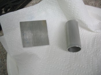
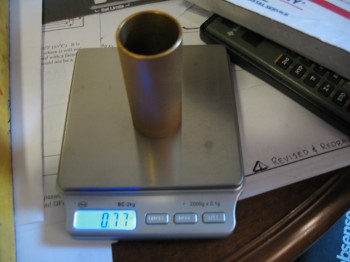
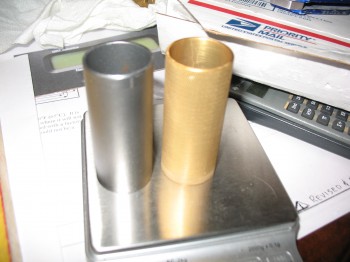
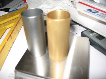
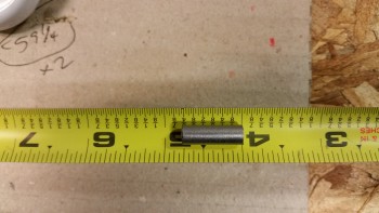
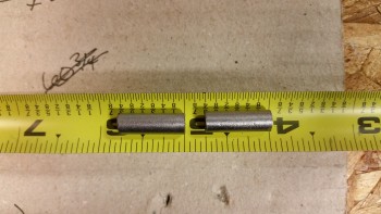
12 June 2013 — Below is the 2.7″ long x 1″ diameter tube that I just received from my buddy Marco. Again, he was nice enough to cut & cross hatch this piece of 6061 aluminum for me as a replacement for a slightly corroded 4130 tube piece that had been attached to my Davenport leaf spring.
To recap, this short tube slides over and is attached to the elevator torque tube, so when the pitch trim actuator arm extends or retracts it moves the narrow end of the leaf spring either fore or aft, thus rotating the elevator torque tube & in turn adjusting the elevators slightly up or down to trim out the airplane.
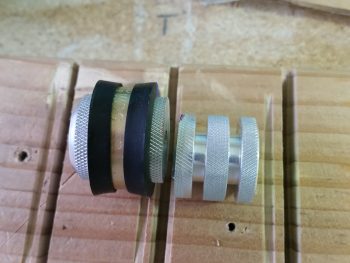
I used 6061 aluminum as a replacement to the original steel piece for 3 reasons: 1) It was available in the correct Inside & Outside diameters vs 2024 aluminum. 2) Weight. Obviously 6061 is much lighter than 4130 steel (see 2.33 vs 0.77 oz weight comparison below). 3) Although this piece won’t be mounted in the elements, 6061 has better inherent anti-corrosive properties than 2024 and especially compared to 4130 steel.
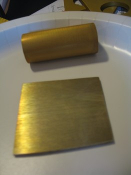
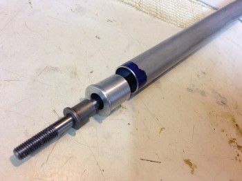
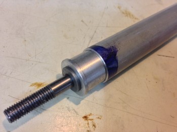
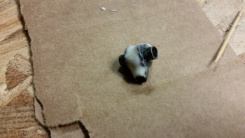
Next I prepared the surface of the Davenport leaf spring where I had previously removed the steel attach tube in order to flox in the 6061 aluminum attach tube. I used some sand paper and my ever trusty PermaGrit tools.
I then floxed in my newly machined (thanks Marco!) and Alodined 6061 attach tube into the glass attach “hook” of the Davenport leaf spring.
•••
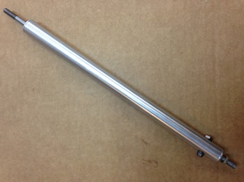
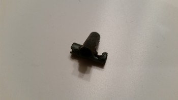
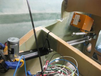
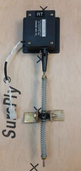
13 June 2013 — I took some time to assemble yet another new toy my buddy Marco had machined for me: the 4130 Steel RT1 Roll Trim Handle (he sent it with the Davenport mounting tube that I just covered in my previous posts). Once again, he did an awesome job in making this out of a blank steel sheet. You can see his post on the RT1 machining process here. As for the Birch plywood mounting tab, I had cut that out last year while at the wood shop on base.
OPERATIONAL NOTE: Both the actuator pitch trim and mechanical roll trim systems shown above are no longer being used, both being replaced as described below. However, the RAM ball mount made it through to the final panel cut and will be installed just a skooch higher than the spot shown.
•••
14 April 2014 — Since January I’ve had an ongoing email conversation with Vance Atkinson about his venerable EZ Electric Trim System. Vance’s pitch trim system is similar in a vein to the Strong pitch system in that it acts both in a linear motion, and some what parallel to the control inputs… or at least much more oblique than a Davenport leaf spring pitch trim system. From what I’ve read though, and not having personally flown behind any of them, the Strong system has had both good and bad reports. The Davenport system seems to get high marks, but it’s significantly heavier and in my configuration would need to be mounted on the center instrument panel leg post, and I want to free up that space for other components while of course saving weight. Moreover, the Atkinson pitch trim system uses an aircraft quality actuator and the spring assembly is made of aircraft grade metals.
Below is a picture of Bernie Siu’s Atkinson pitch trim system that he installed in his Cozy. As can be seen, the trim assembly mounts out of the way on the side of the fuselage just forward of the panel, and connects to the elevator control rod via rod end. Bernie has a great detailed explanation of his experience with both the Strong and Atkinson systems here.
So, after some discussions with my building buddy Marco, we decided to pull the trigger and make a couple of these guys. As per usual, I provided the financial backing and he provided the talent! (ha!) I ordered the materials and hardware required for two of these suckers and had it all sent to Marco’s production shop of magic and wonder.
Not surprisingly, within short order (mere minutes most likely!) of receiving the required stuff, Marco had worked his machinist’s magic on his lathe and mill to give us the beginnings of two beautiful Atkinson EZ Electric Trim Systems.
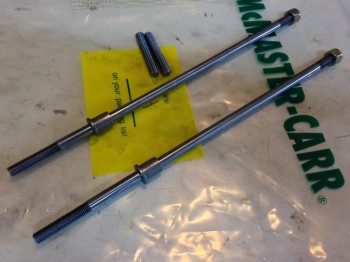
Of course, once again, Marco has done some masterful work and produced some amazingly beautiful machined pieces!
(Bravo my friend!)
•••
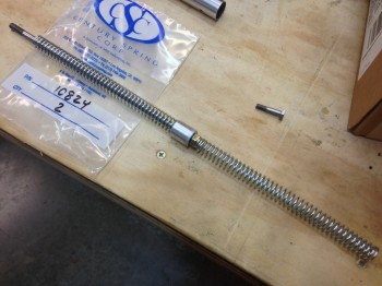
24 April 2014 — The Atkinson Pitch Trim System project marches on! After receiving new parts and materials, Marco has machined some simply beautiful spring housing assemblies. Which, speaking of springs, they seem to be the most problematic part of this whole endeavor.
When Vance designed and built this pitch trim assembly back in the 1990’s, apparently both True Value and Ace hardware stores carried a spring known as “Compression Spring p/n 196.” Well, after emailing, calling and perusing a half-dozen True Value and Ace hardware stores–and those big Blue and Orange guys as well–for those of you that are interested, I can assure you that that spring is no longer in their inventory. Nor anything close to it to serve as a suitable substitute.
However, after one Amazon & two Century Spring Co. orders for springs (I won’t bore you with Century Spring’s minimum order amount), it looks like we finally found a suitable spring, and possibly one viable candidate . . . subject to testing of course.
Now that we have a viable set of springs, and can use those specs to narrow in our search for some springs that let us lock in our control forces (FYI – Vance had three sets of springs [that fit!] that he tried out before getting the right “feel” on the pitch controls).
In addition, I’ll be ordering the actuator this week so that at least initial testing can begin, which will help in selecting some further spring candidates.
•••
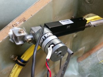
27 May 2014 — My buddy Marco finally received the Motion Systems Actuator that I ordered from them at the beginning of May. All reports from Marco are the fit & finish are excellent. We’ll most likely have to play around with various spring tensions to lock in the operating parameters for our respective Long-EZs, but of course fine-tuning is expected on any pitch trim system install.
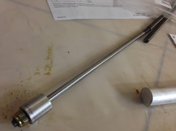
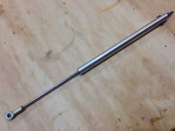
Here are some excellent shots of my completed Vance Atkinson EZ Electric Trim System. Of course the credit goes to both Vance who designed & perfected the system, and Marco who built it to perfection using the plans Vance & other builders supplied us.
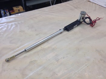
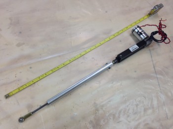
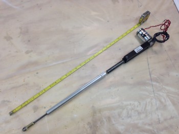
Although I have yet to actually test this system yet, I am incredibly pleased & excited to be using this pitch trim system in my bird. My initial thought is that it was definitely the right choice.
•••
27 February 2015 — The magical truck that has all the airplane parts stopped by today to deliver an order from Wicks. Since Wicks had a 10%-off special on all things composite for February I pulled the trigger on another gallon of West epoxy for the final finishing of this bird. I also ordered something that I thought I had on-hand, but after my recent 100% inventory of EVERYTHING, I realized I didn’t: a piece of 1/4″ diameter x 0.028″ wall 4130 steel tube.
What is this used for you might astutely ask? Why, my “new” roll trim system.
But first, you may remember that back in June 2013, my good friend, fellow Long-EZ builder, and MASTER machinist, Marco, made me the metal parts for my standard plan’s version roll trim. From various Canardian PIREPs roll trim is not used a lot and I wanted to keep the plane as light as possible. Then later, some other Canardians I spoke with talked about the inconvenient location of the plans positioned roll trim lever (read, at right-thigh seat level…not good for someone with more robust thighs!). A few ingenious builders from the Old Guard had clever workarounds to make the roll trim more mechanically user-friendly… and much better ergonomically.
But after a fair amount of thought I came to the conclusion to strive for K-I-S-S. I have a very nice, capable china-hat trim switch on a cool Infinity stick, so why not use it for both trims: pitch & roll. Yes, it may mean literally a few extra ounces, so I’m doing the weight rationalization dance (kind of like ordering dessert after a big meal!), but the simplified operationally convenience will optimize cockpit management in my opinion.
I looked at a myriad of different roll trim ideas out there, many using the “omega”-shaped composite spring (“Wright/Hanka Spring”) firewall aft, but I figured I would try out Waiter’s (aka John McAvoy) Roll Trim System as he describes on his site IFlyEZ.com. Since nearly all plans for EZ Roll Trim systems revolve around the most expensive item involved: the Ray Allen RAC T2-10A servo, then I’m out literally $10 in parts if I want to switch to the Wright-Hanka style trim spring in case I don’t care for Waiter’s system. A contributing reason for my choosing Waiter’s system is its location just aft of the pilot’s seat, in some real estate that isn’t being used for anything else.
 Also, although this system is light (9.5 oz vs. plan’s roll trim of 4 oz), it still puts the weight of the components forward of the firewall rather than behind it.
With my decision made, I plan to knock this out in the next day or so.
•••
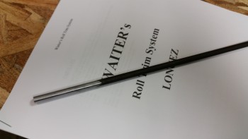
28 February 2015 — With all the parts assembled and on hand for the new Roll Trim System, I went to work making the ‘X’ tube (which is actually more akin to a plus sign +) that is created by welding two 3/4″ pieces of the 1/4″ dia 4130 steel tubing together. After welding (or soldering) these two pieces together, one tube will get a washer slid onto each end that is also welded/soldered into place.
I went to work to finalize the setup of my TIG welding corner and dial in my TIG welder.
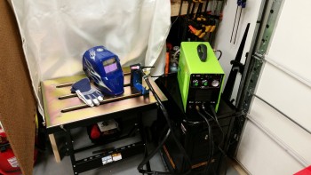
After getting the welding station situated, I ran a number of beads to get back into the swing of things. Although woefully still needing much more stick time on the TIG, I set about making the ‘X’ tube by knocking off the protective coating of the 4130 tube and then cutting the two 3/4″ pieces.
I realized after blowing a couple of holes in the thin-walled tubing on my first attempt at making the X-Tube, that I had dialed in the wrong numbers on the TIG box. Since I was using a 1/16″ Tungsten electrode, I had mistakenly dialed in the amperage for 1/16″ thick 4130 steel versus the correct amps required for 0.028″ walled tubing. Another issue I had was that my filler rod was about twice the size I needed, so getting it to flow out without burning a hole in the thin tubing was a bit tricky. Regardless, here was my first attempt at making the X-Tube:
After dialing the amps way down on the TIG welder, I was able to eke out an X-Tube that would handily do the job. X-Tube #2 was not pretty by any standards, but a quick brush up with the Dremel and some “Flocro” (Flox + Micro) using 4-year old MGS 335 proved to do the trick to make it presentable (see side note below).
Although not a beautiful specimen of welding, this little guy is strong! I had re-read some of my notes on welding 4130 steel & it stated that 4130 is some tough stuff, and boy they weren’t kidding! I had a slight bubble on the inside of one of the tubes that protruded about 60 thou (0.060″) into the tube. No problem, I grabbed a cheap Harbor Freight 3/16″ drill bit to hone out the holes to ensure both tubes were clean. That 60 thou 4130 slag bump chewed up the end of my bit like it was nothing! I had to pull out my high-end drill bits to clean this sucker out.
I let the Flocro cure until is was just still soft enough to work. I cleaned it up and then let it cure another couple of hours as I messed about with my headrest/rollover design. After it had cured, I did one final clean up and then shot it with gloss black Rustoleum primer/paint. 
I then set up a shop light about a foot away and let it dry.
After a few more hours I dry fitted the X-Tube onto the other components, and all fit well. I then left it alone to get in a good overnight cure.
OLD MGS 335 side note:
As I mentioned before, I was playing around with some old MGS 335 epoxy and hardener for a cosmetic makeover of the X-Tube. When I say old, this is stuff that I had left with Marco back in the Summer of 2011 when I went to Germany. The hardener had turned a puke brownish-green color and I had no idea what it would do. But, my experience with MGS is that the stuff is magic, and since this was for purely cosmetic use without any structural expectations, I figured what the heck. At first I thought the hardener was chemically dead, since after a couple of hours it was still pretty mushy. But I left it in front of a heater, and lo & behold, a couple hours later it was hard as a rock.
•••
1 March 2015 — Well, let’s say it’s 95% complete. I still need to cut two 1/16″ 2024 aluminum “L” brackets to attach to the X-Tube (via the 3/16″ bolt) to then be attached to the aileron control tube with a stainless steel hose clamp on each aluminum “L” bracket. I don’t have any 1/16″ angled aluminum on hand, so I’ll wait until I put in my next consolidated ACS order to pick some up (to save on shipping costs).
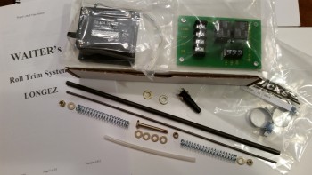
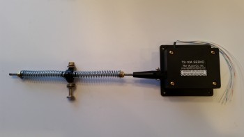
Nonetheless, here is my new, completed Roll Trim system:
•••
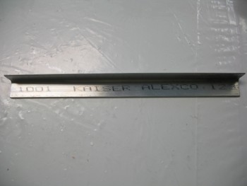
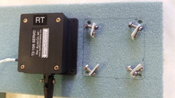
25 March 2015 — The only I thing I needed to construct to finish up the roll trim as per Waiter’s detailed instructions was the two 1/16″ thick 2024 aluminum angle tabs. These tabs hold the X-Tube to the control tube (which transits down the side of the fuselage).
I didn’t find any angled 1/16″ 2024 aluminum as I rooted around in all my metal stock, but I had a nagging feeling that I had ordered a piece. Thus, last night I carved out some time specifically to research the case of the missing angled aluminum (queue dramatic music). A significant motivation for me to look was that it was going to cost about $17 to have a $3.50 piece of aluminum sent to me from Aircraft Spruce.
First, I found it in on my master spreadsheet and I had even listed it as being for the roll trim build. That meant that I should have it on hand. With various parts of my EZ project literally having been scattered about 5 locations around the world, I thought maybe I might have lost it in transit. Well, I then checked my invoices and found the box that it had been shipped in, along with the aluminum tubing for the fuel lines. Since it was wrapped in brown paper at the bottom of a tall box, I had missed it at the bottom, dimly lit corner behind & below all the various tubing and wire bundles.
Anyways, an hour blown on looking for my aluminum angle piece, but the mystery was solved & case closed!
I set my sites on knocking out the tabs for the roll trim assembly since this will finish up the actual construction of the roll trim assembly, and all that will be left is the installation & wiring up of the roll trim system.
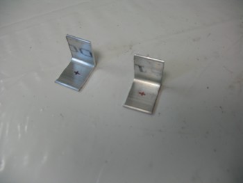
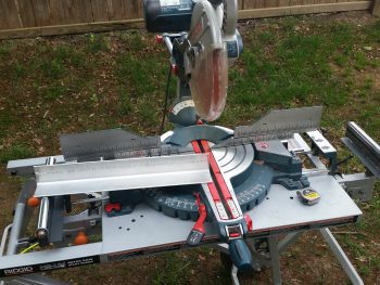
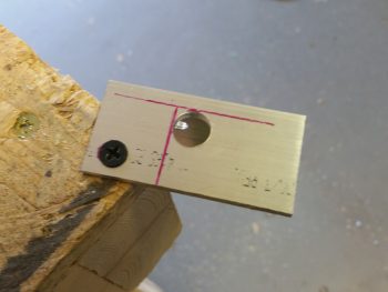
I checked each end of the 1/16″ angled 2024 to ensure it was square, which both sides were. Then after making a mark at 3/4″ I simply used my small chop saw with a wood blade, and very slowly cut the aluminum. Repeat for the second one and voila! Two tabs.
As per Waiter’s plans, I marked the spots for the mounting holes in center going top to bottom (3/8″) and 1/2″ from the side (this is 1″ x 1″ angled 2024).
I drilled a small pilot hole in each tab, then finished up with a 3/16″ hole. I deburred the holes & then checked the fit of the AN3 bolt.
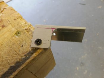
I then cleaned up the edges with the Dremel Tool and gave the non-drilled side tabs just a bit of a radius where the pipe clamps will be located as they hold the roll trim assemble to the control tube.
I then mounted the tabs to the assembly. They fit great and everything looks good. I’ll Alodine these tabs later on when I do another batch of aluminum components.
Here’s a few shots with the mounting tabs in varying positions on what I’m going to call the COMPLETED Roll Trim assembly!
•••
9 April 2015 — Today I was able to Alodine the Roll Trim attach tabs along with some other pieces for the roll bar assembly.
With these tabs Alodined, the only thing left to do is install this sucker!
•••
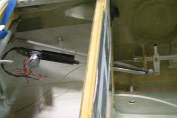
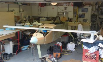
17 October 2016 — Today I spent a few minutes getting a feel for how the Atkinson pitch trim assembly was going to get mounted into place. As you can see, I wedged the pitch trim assembly up into place using a 2×4 resting on the rudder pedal.
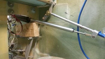
Here’s a shot from the front of the plane.
Here’s another shot with the actuator motor turned facing down, which may be required for clearance for the top of the nose. I also need to set my rudder pedals in their final position and check that my right foot has clearance with the pitch trim assembly.
After I removed the canard, I tested moving the pitch trim assembly aft into the area between F22 & the IP. Although my foot could be very close to the actuator assembly (what isn’t a tight fit in a Long-EZ???) this may just be a viable mounting position.
•••
19 October 2016 — With a really good idea of my rudder pedal geometry now (see Chapter 13 nose for rudder pedal adjustments), I decided to re-attack the placement of the Atkinson pitch trim assembly. After mocking it up in different spots for a bit, I pretty much concluded that it has to go where I had planned for it to, except with one minor modification: it most likely will have to be mounted at an angle with the actuator motor leaning from 30-45° inboard to clear the upper curvature of the nose.
•••
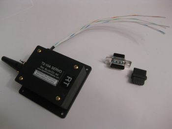
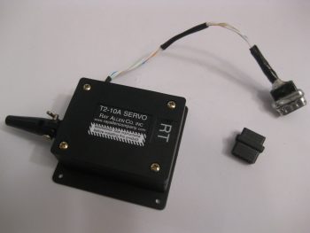
21 October 2016 — My second (the other being the autopilot roll servo) electrical-related task of the day was to terminate the 24AWG wires coming out of the RAC servo that I’m using in my roll trim system. I decided to try a little trick that Bob Nuckolls has for modifying a DB9 connector to use as an inline type connector.
Below you can see I’ve already removed the metal housing from the female side of the DB9 connector.
I then had to remove the tabs from the male side, but this being my first time making one of these I removed a bit too much of the flange, so when resoldering the sides back together I had to try to bridge the gap, which if you’ve used solder you know it’s not a good gap filler or bridging material. I later cleaned off some of this excess solder but pressed on after I took this pic to get this thing completed.
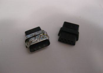
I guess I should have taken an interim pic of the individually terminated wires with the D-sub pins, but here’s the final connector after I added some E6000 adhesive for essentially a potting material & strain relief on the back side of the connector.
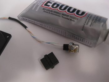
The female side of the connector will get D-sub sockets terminated onto the wires and with the wires terminated, all of this will get heat-shrinked together to complete the final connection of the 2 connector halves.
For what is essentially a 4-pin connector I’m not really sure if I’d use one of these again. I think for the future I’ll look for a more elegant off-the-shelf solution to use for the RAC servo wiring, or any smaller gauged wires for that fact.
•••
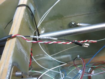
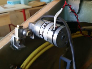
20 November 2016 — I started out today labeling the power wires coming off my Atkinson pitch trim servo motor with heat shrink labels on both ends of the wire. As you can see I had to unravel the twisted wire then retwist them back together after the labels were on. However, since the servo motor came from the supplier with these wires, I wanted to test them to see how they held up under heat & fire. I snipped a test piece off and tried to burn it with a lighter for a good couple of minutes to no avail. With my impromptu wire fire rating test complete, I then went ahead and affixed the labels and retwisted the wires.
I also went ahead and removed a good portion of the outer sheathing to the 3-wire cable coming from the Atkinson pitch trim servo positioning indicator. The black wire of the group that I labeled and terminated with a FastOn connector will be grounded on the main panel ground buss (G4), while the red & white wires will tie together into one extension wire to feed an input into the GRT HXr to show trim positioning graphically on my EFIS.
•••
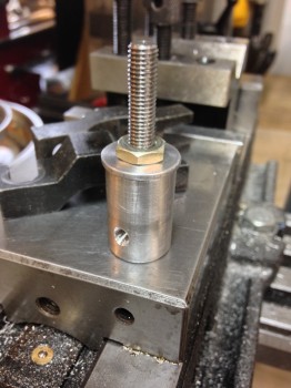
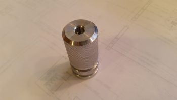
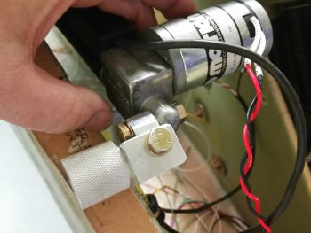
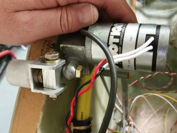
8 April 2017 — Today I received the lathed knurled insert with flox grooves that I designed as a nose sidewall mounting hardpoint for the pitch trim actuator. Of course –as fantastic as this looks– I obviously did NOT make it using my primitive neanderthal methods. Marco graciously knocked this out on his lathe in no time flat and threw it in with the AEM box that he shipped to me literally right after machining this piece.
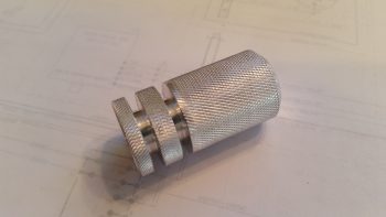
Here’s another shot of the Marco-machined flox-ready nose sidewall mounting hardpoint for the pitch trim actuator.
•••
5 May 2017 — Today I decided to focus on getting all the aluminum parts cut that I will need in the near future, and specifically focus on one of the critical completion items on my list before I can move forward with closing up the nose: the actuator assembly install for my Atkinson pitch trim system.
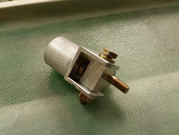
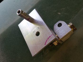
I just got some more 1/8″-thick-sided (1″x1″ overall) 6061 U-channel in from ACS that I ordered earlier this week. I pulled out the big saw and cut the U-channel 1″ wide to match the diameter of the knurled pitch trim actuator installation hard-point that Marco machined for me (shown below), and a somewhat “D” shaped rotating bracket that is the actual attach point for the pitch trim actuator… which gets installed inside the U-channel cut above (all this is shown below as well).
Here’s the U-channel bracket that attaches to the knurled pitch trim actuator installation hard-point. I ended up scrapping this one and making another one with the locations of both sets of mounting holes dialed in to better fit the tight installation requirements.

Of course, to figure out the exact installation configuration of the pitch trim actuator, I needed to reinstall the canard.
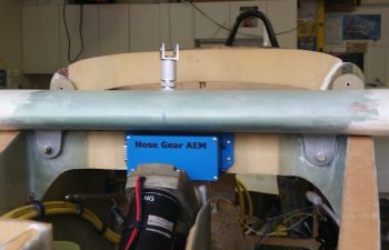
I quickly collected up yet another Marco-made item (thanks Brother!), the Nose Gear AEM box to verify that my dimensions were correct so that it fit in place with the canard installed, and it does.
Beyond reconnecting the elevator control tube I also verified clearance between the elevator control arm and the big power cables mounted just below it to the side wall. Again, plenty of clearance with the elevator control arm at its lowest point.

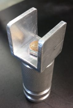
Alas, after spending a fair amount of time dialing in the installation configuration and location for the pitch trim actuator, I finally came to the point where I had to sadly cut Marco’s beautifully machined hard point creation in half. The side wall where this thing will get installed is simply much narrower than the length of this insert. I would have chosen to keep the lathed flox grooves on the aft side, but since he could only get the 1/4-28 thread tapped down about 3/4″ of the way into the bolt hole, I did’t want to risk not having enough threads left for a bolt to really bite into. So, I mounted it into a tight-fitting Adel clamp and carefully cut it on the big saw.
I then spent a good hour+ measuring, drilling, filing, sanding, and finalizing the interior pivot bracket & external mounting bracket that physically attaches the pitch trim actuator to the side wall hard-point mount.
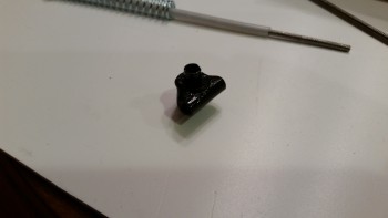
You may have seen that in installations on other builders’ projects that this actuator simple gets mounted with the actuator motor oriented vertically, either up or down. Unfortunately, if I went actuator motor up, I would need to glass in a bump on my nose to clear it. If I mounted it actuator motor down, then I would have to contend with it interfering with my right foot while working the rudder/brake pedal. This all becomes paramount with the understanding that the actuator must be able to pivot side-to-side so that the other end of the pitch trim assembly, which is mounted to the elevator control tube, is allowed to freely pivot with the left-right movement of the control stick.
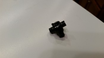
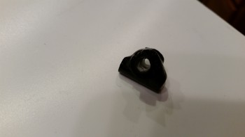
Thus, I note all this because of the way the physical mounting tab is situated on the pitch trim actuator, in its comparative ease of being mounted vertically, either up or down, which allows for the required side-to-side pivoting action. However, once mounted with the motor positioned horizontally you could easily realize an up-down pivot action –which isn’t needed or wanted– but not the required side-to-side motion. Obviously then, I had to account for the actuator mounting tab’s configuration with an intermediate bracket that provides this required side-to-side motion for the now “incorrectly” mounted actuator.
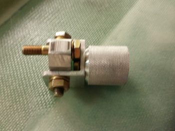
Here’s another shot of the pitch trim mounting bracket assembly.
I then detached the pitch trim mounting bracket assembly from the actuator motor mounting tab and snapped a few shots of it at different angles.
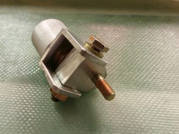
I still need to fine tune the fit & finish of the individual parts, but as you can see, the main configuration design is complete. And I haven’t noted anything thus far that will preclude this from working as designed.
•••
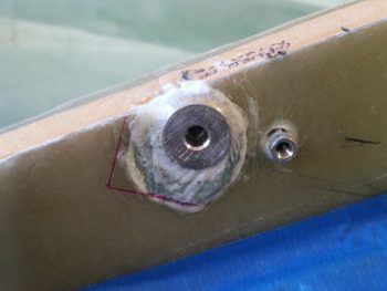
7 May 2017 — I actually took the first 2 pics yesterday, but since I was heading out to meet some friends, and was trying to field an influx of phone calls, I missed my window to mount the pitch trim hardpoint into the sidewall.
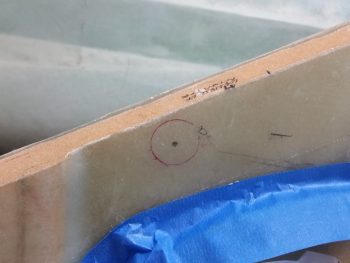
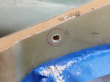
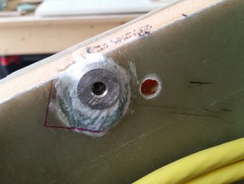
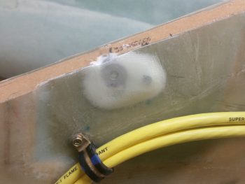
No worries since it just gave me more time to figure out my exact plan on how to embed the pitch trim hardpoint into the right sidewall. Below you can see that I started drilling out the hole where the hardpoint will get floxed/micro’d/flocro’d into place.
Today I finished the pitch trim actuator assembly hardpoint install, although when I got home my phone was dead, and it being my current camera I didn’t get a few key intermediate pics… and I really needed to proceed with this install since I’m falling behind schedule on this build!
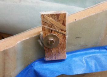
I took a scrap piece of wood, drilled a 1/4″ hole into it, then covered the outboard side with packing tape. Not shown is the clamp and the wedge that I used to keep the head of the bolt fairly parallel with the aircraft CL, and the face of the mounting hardpoint near 90° vertical. This pic was taken a little while after I had removed the clamp and the wedge, when clearly my phone was recharged.
Here’s another something that I didn’t get a pic of earlier. Apparently, when I drew my install point target circle, the geometry of how the mounting hardpoint fit into the sidewall was different when I could actually test fit the hardpoint piece IN the sidewall. The original hole started in the lower left corner in relation to where I eventually mounted the hardpoint, which of course meant backfilling the open area of the hole with spare Divinycell foam.
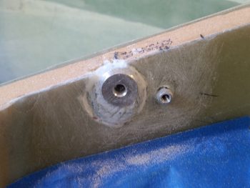
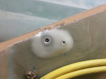
I also knew that even though I drove the position of the mounting hardpoint as far forward and up as I could, that I still may very well need to rewicker the mounting bracket to get the spacing and/or alignment of the pitch trim assembly correct. In addition, I know this hard point install won’t win any beauty contests, but just keep in mind that this will all get sanded, floxed, and covered with 2-3 plies of BID when the nose top gets constructed.
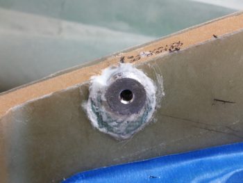
Here’s a downward shot of the pitch trim mounting hardpoint showing the mounting face of it straight in comparison to the sidewall. Also, although hard to tell in the pic, the face is also vertical where the sidewall tapers out slightly as its height increases.
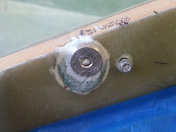
With the micro & flox pretty much cured, I then attached the mounting bracket to test fit this sucker!
I took about 10 minutes to file down both the top & bottom edge of the swivel bracket to allow for a better fit inside the U-channel mounting bracket. Below you can see it swiveled inboard.
And here it’s swiveled outboard. If it doesn’t look like it’s swiveled outboard much, you’d be right! I still need to shave down the width of the swivel bracket on the outboard side by about 0.10″ so that it has clearance to swivel outboard the required amount.
I then mounted the pitch trim actuator and assembly. I could instantly tell that this entire assembly was sitting about an inch low. My suspicion when mounting the hardpoint proved correct, meaning I’ll have to rework the mounting bracket assembly. I’m still very happy with this install though since I’ve refined my target positioning from about 50 meters down to 5 meters . . . meaning that while not in it’s final, spot-on position, it’s very close and very workable!
Here’s a wide angle shot of the entire pitch trim assemble. In his install directions, Vance Atkinson states to mount the pitch trim assembly at a point on the elevator control tube about 1.5″ forward of where the control tube passes through the instrument panel. Right now, I’m about 3/8″ (0.375″) forward of that (so, 1-7/8″ forward of the panel). I’m hoping since Vance had his assembly pretty much parallel with the aircraft waterline, and mine is much more aligned with the actual angle of the elevator control tube, that the added 3/8″ won’t be an issue.
[Note: As I understand it, some Strong pitch trim units installed in the same position where I’m mounting mine proved to be a little problematic, with resulting minor oscillations and difficulty in trimming the aircraft. Of course I’m not using a Strong unit, but nonetheless I’ll keep my eye on these potential issues and work to correct them if need be.]
Ok, although not a slam dunk right out of the gate, I am –again– very happy with how the pitch trim unit install is going. I like it up front here because although it’s tight quarters where I’m installing it, it moves weight forward, keeps the aft part of the airplane more clear of components, results in much shorter power wires, and should keep my comms clearer & more noise free due to the motor works being away from any of my comm circuits.
•••
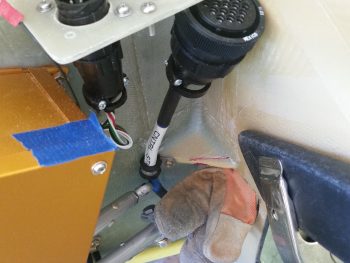
8 May 2017 — I started off today checking the clearance for both sides of the pitch trim actuator and realized that in extreme forward and aft stick situations, the elevator control tube had its motion limited by the corner panel reinforcement plate that I added. I marked the corner plate and then Dremeled out the offending area (camera side of the magenta line).
As you can see, before actually starting I wedged a leather glove in place above the control tube to keep from inadvertently nicking it with the Dremel. Before I did any cutting, I also taped a spare piece of small angled aluminum to the blue control stick cable to protect it as well. Of course, I forgot to get an after pic, but it’s pretty much a shot of everything from the magenta line out simple not being there.
So here’s a shot of the first significant mod of the pitch trim actuator bracket, which I’m calling “Mod 2”. Note that I pulled the swivel bracket from between the sides of the U-channel bracket and mounted it up top. This really got the pitch trim arm up where I wanted it, at a line above the big yellow power cables. Also, I did play around some with the bolt hole positions before moving on to “Mod 3”.
For Mod 3, I redesigned a whole new 1/8″ 2024 aluminum bracket.
I drilled the mounting holes and then removed the area on the top plate where the actuator will fit into.
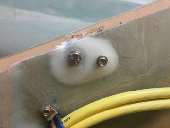
I then mocked it up and marked where a second hardpoint will go into the sidewall. This will help alleviate the stress on the front bolt from the forward and aft pushing & pulling action (which places either forward or aft twisting action on the mounting plate).
I then located and drilled the hole for the second pitch trim actuator mounting hardpoint.
After the second pitch trim mounting hardpoint was cured, I then pulled the plate and marked it up for cutting to reduce its footprint and shave off a little weight.
Here’s the pitch trim actuator mounting bracket reinstalled. Note the second, smaller, bolt holding the aft side of the bracket securely.
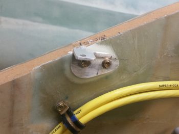
I then reattached the swivel bracket atop the sidewall mounting bracket.
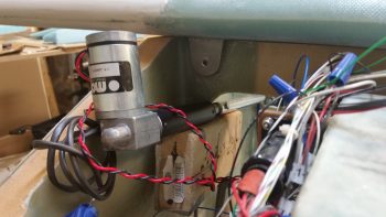
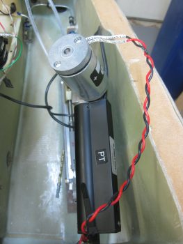
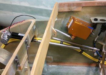
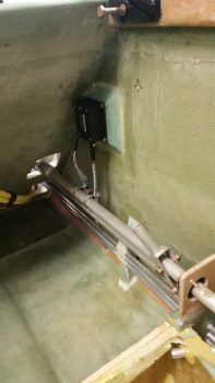
And finally, here are a couple of shots showing the installed pitch trim actuator unit.
And one more shot that provides a good view of the mounting bracket assembly.
I thought this post would contain overwhelmingly good news on my pitch trim actuator installation, but it looks like more mods will be required. As you can see in the video, since the nose sides curve inward at a fairly decent rate from the instrument panel forward, then aligning the pitch trim actuator in line with the elevator control tube is simple impossible to do in a Long-EZ (it may be doable in a Cozy, I don’t know) . . . at least this Long-EZ.
So, as you’ll see in the video, after trying different ways to mount the aft end of the pitch trim actuator arm to the elevator control tube, I eventually had to settle on mounting the rod end onto the inboard side of the control tube clamp bracket that Marco made for me. Unfortunately, that created another issue:
Obviously I still have some more work to do to dial in the pitch trim unit so that it will be fully functional as designed . . . thus, the slog continues!
•••
11 May 2017 — Today I set my sights back onto the Atkinson pitch trim system. Having received my reamers via UPS this AM, I was ready to drill and ream a nice round 1/4″ hole in the elevator tube to mount the control arm of the pitch trim actuator.
First, I spent a good 45 min dialing in the new configuration and physical mounting of the pitch trim actuator by redrilling the 2 mounting holes in the mounting bracket. Not only was I moving the entire unit aft a hair, I was also rotating the front of bracket down a bit more while the aft side dropped down some as well, but not as much as the front.
Once I got the pitch trim actuator assembly newly aligned, and the mounting hole in the elevator tube was ready to be drilled, I set up the control system within the plan’s specs with the elevators at neutral and the control stick at ailerons level, which is actually about a 5° stick grip lean to the left — again, as per plans. I then drilled out the hole in the elevator tube and mounted the control arm of the pitch trim actuator.
Once I tested the newly realigned pitch trim system, the up trim worked fine but the down trim didn’t work at all. Apparently, if you’re prone to moments of just being dumb, then you can expect issues like this! Apparently, in my haste to get this pitch trim actuator in this bird, I forgot to double check its current position. Since the actuator arm was all the way in, then when I threw the switch for it to push the elevators up, it did so with no issue. But then when I went the other way, well, by the time the actuator throw ended the elevators were merely back at level . . . and didn’t go down below the level line at all.
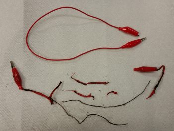
Another issue I had was just a little battery fire, or so I thought –after I removed the actuator to set it at its midpoint position– as I was coming around the nose and had moved the actuator power wires. Well, as I rounded the nose I could see a bit of fire right on top of the battery. Not sure what was actually burning, I yanked the wires off the battery and kicked it across the floor so if it decided to do something violent I had the fuselage between me and it.
Well, the fire went out immediately, but there was a good bit of smoke. Apparently one of my patch cords shorted out and literally blew apart and started burning. It’s interesting that none of the mil spec wires had any issues, but a couple of the cheaper leads were destroyed. A few minutes later I felt the battery to see if it was warm, and it wasn’t. I then checked voltage on it and it was a bit low at 12.59 volts. But then again, I haven’t charged it in a few weeks and I have been using it a lot. An exciting little sideshow to be certain, but with that out of the way, I got back to the task at hand.
After about 10 minutes of having the garage open and a fan turned on to clear out the smoke and smell from the burning battery wires, I went to work to fix the actuator configuration by simply taking the actuator out of the nose and extending it until it was half out (1.5″ out, with a 3″ total extension). I then remounted it, verified and reset the control system to specs, and the drilled the new hole. When I tested it the second time around it worked like a champ (see video below).
•••
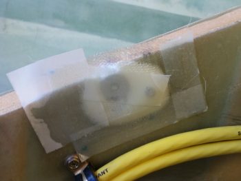
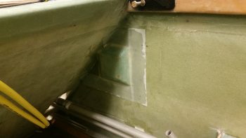
15 May 2017 — Today I started off by prepping the two hard points for the pitch trim actuator to be glassed over with 2 plies of BID. Here’s the before pic of how it looked when I started.
And then after a few minutes of good sanding.
I then cleaned it up & prepped it for glassing.
I was going to use foam to fill the space in-between the two hard points and the around the aft side of the small hard point, but it turned out to be more trouble than what it was worth. At least in my opinion. So, I just made the flocro a little dryer so it wouldn’t run and used it as the filler all the way around.
I then prepregged 2 plies of BID and laid them up. I also peel plied those areas that would easily take peel ply without a hassle.
I did do one more task (not pictured) with the leftover epoxy: I mixed it into thick flox –only flox– and sealed the parts of the bolt holes in the pitch trim bracket where I had drilled them out in search of the right position. Their latest position had each of the bolts covering about 60-75% of there own hole edges, so instead of cutting a whole new bracket, I decided to flox up the open areas of the holes and leave the bolts alone in their own holes.
I ran out to run some errands and when I returned all my composite tasks of the day had cured.
I pulled the peel ply from the pitch trim actuator mount hardpoint layup and cleaned it up a bit. I then redrilled the holes and removed the protective saran wrap I had placed in the holes to keep unwanted epoxy out. I then tweaked the glass around the holes just a bit more to allow for each respective bolt to fit back into their hole. I then test mounted the pitch trim actuator bracket back onto its new hardpoint base.
If you’re thinking 2 plies of BID might not be robust enough for the pitch trim bracket, no worries! When I glass the nose top in place these hard points, being right on the edge, will get another 2 plies of BID over them.
•••
9 June 2017 — Today I whipped up some flox to mount the slightly undersized threaded rod of the lower roll trim spring assembly into the RAC servo’s clevis.
•••
13 June 2017 — Today I was able to work on the Roll Trim mounting pad. I had ordered K1000-06 nutplates for the 6-32 screws that will be used to mount the RAC servo to the fuselage sidewall. Well, I had a “Doh!” moment when I realized that since the RAC servo has corner mounting holes, I should have ordered 90° corner nutplates. Oh well, since the Roll Servo is fairly light and in normal ops not an overly used device, I made a command decision that one rivet tab would do to hold each nutplate in place on its respective G10 Garolate nutplate base.
[Note: Normally this servo would get mounted straight to the sidewall, but since I had to kick in my control tubes about 3/4″ inboard to allow for the CG controls, I am simply “extending” the fuselage sidewall inboard 3/4″ with this foam base]
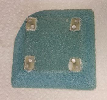
Once I got all the nutplates riveted to their 1/16″ G10 base, I mounted them to the RAC servo and figured out their exact location in the foam. I then notched the foam at each corner and embedded each nutplate assembly.
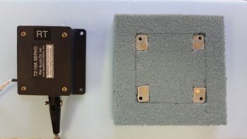
I then taped up the bottom of the RAC servo to use it as a guide, and then mounted the nutplate assemblies back onto the servo. I then micro’d up the bottom of each nutplate assembly and the corner notches in the foam. I set the nutplates (with servo) in place, and once satisfied that they were all in the right position, weighed down the servo to press the nutplates into their respective notched corners (I failed to get a pic prior to this of having shaped the edges of the foam to allow for glass transition to the fuselage sidewall).
Later, after it all cured, I filled each nutplate with plastic/saran wrap to keep the micro out of the nutplate threads.
Later still, I prepped the foam roll trim servo base with micro and micro’d it to the right fuselage sidewall just aft of the pilot’s seat. I then laid up 3 plies of BID over the foam base and then peel plied the edges with 2″ peel ply tapes. I double checked the elevation a few times using the RAC servo with the spring push/pull assembly attached.
With only a few minor tasks left, like drilling the screw holes and pulling the protective plastic wrap out, I’m calling Chapter 17 – Pitch & Roll Trim Systems, complete!
•••
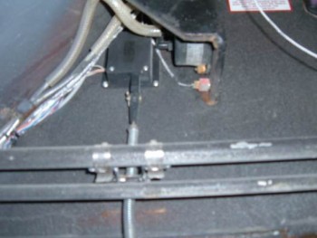
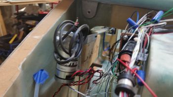
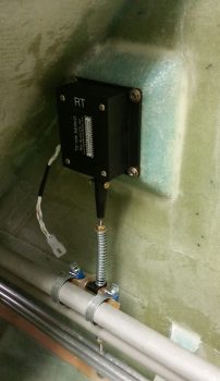
14 June 2017 — Today, for the Roll Trim servo mounting, I carefully drilled out the glass covering the 4 corner #6 screw nutplates. I then pulled out the plastic wrap that I had stuffed into each nutplate to protect it from epoxy. Once all the mounting holes were clear, I then mounted the RAC Roll Trim servo in place. After a slight adjustment upwards of the spring assembly, I then set it in place and loosely attached the 2 hose clamps that when eventually installed for good will allow the servo assembly to rotate the control tube (spring arm up or down), which translates into aileron left or right movement for trim.
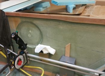
Here’s a closer shot of the mounted roll trim assembly.
•••
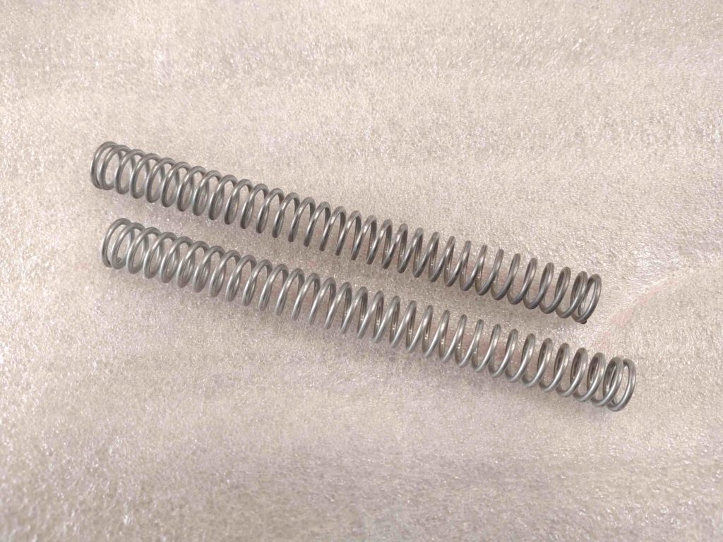
10 November 2019 — After 5+ years of looking, I found ’em! Thanks Mike!
One system in the Long-EZ that is not well-covered out there in the building community ether is the pitch trim system. That is, if you’re not going with the original stock springs and mechanical lever.
For electrical pitch trim the overarching style in use on the Long-EZ seems to be the Davenport style, where a composite paddle is secured to the elevator torque tube and then connected to typically the same size actuator as used for the Landing Brake. Reportedly this works fine and I had planned on going in that direction, but fairly quickly realized that with the shear amount of stuff I had packed into the panel –not to mention my odd-duck Triparagon– that the Davenport style was not going to work for me.
My seemingly-elusive search culminated in my choosing an Electric Pitch Trim system that was designed by Cozy IV builder Vance Atkinson. Most canardians know Vance since he makes & sells the spiffy fuel site gauges. Well, after a discussion in January 2014 regarding his pitch trim system, I decided to use his design in my Long-EZ.
One issue I spoke with Vance about was where to secure the springs he identified on his system overview page. He called out an Ace/True Value Hardware spring #196 that had dimensions of 6.25″ long x 5/16″ diameter. Well, as hard as I and Marco looked for these darn things, we never found them. Even contacting the Ace main office to see if they carried them anymore, to which they replied that they were not in their system any longer.
A few months ago Mike Beasley contacted me to discuss his pitch trim system. He had noted that I was not using my Davenport Leaf Spring + Firgelli Actuator system and wanted to buy it from me. I sent it off to him and wished him luck.
Well, unknown to me until Rough River, Mike had gone down virtually the same decision matrix I had with his own final realization that the Davenport style took up a bit too much real estate and wasn’t going to work for him neither. In fact, Mike, Marco and I had a fairly in-depth brain-storming session on the Atkinson pitch trim system, the result of which was Mike leaning strongly toward it.
Ok, so today I get a text from Mike that he found the ever elusive #196 springs at his local Ace Hardware store! I was flabbergasted since I had looked in at least 15 stores over the past few years, just in case they still had some by any off chance.
Curiosity got the best of me and I went to two local Ace Hardware stores, and wouldn’t you know it –in somewhat of irony– the store a mile from the airport had a bunch of them! I grabbed 4 of them to ensure I had extras, and will probably grab a few more.
Amazing, but here is photographic proof! ha!
Crazy adventure this airplane building. Strange how things work out and how patience truly does pay off sometimes!
One big side note: During the first half of 2014, while Marco was machining my Atkinson pitch trim spring housing, I bought close to $200 worth of springs looking for a 6.25″ x 5/16″ diameter spring. As grateful as I am to Vance for sharing his electric pitch trim system design, after actually getting these #196 springs in hand, I realized he had inadvertently/mistakenly sent me on a wild goose chase. Yes, these springs are 6.25″ long, but they ARE NOT 5/16″ in diameter, ID nor OD. These fit inside the 0.75″ tube and are close to 5/8″ diameter. Might have been a typo on Vance’s diagram, but it definitely made my life an adventure for quite some time trying out springs –based on those specs– that were simply to small to work in the spring tube.
•••