
Chapter 22 – Lights Page
In addition to the main electrical page that is ordered chronologically, I’ve added a separate web page specifically for lights.
3 December 2013 — Well, this past week I was hornswoggled by Wicks Aircraft . . . darn them! They have a really nice sale going on for all their AeroLEDs and Aveo lighting products up until 31 December… 20% off to be exact. Which is a lot of money for expensive lights. Thus, I threw myself headlong into the assessment & evaluation phase of the available nav lights so I could spend money to save money. That’s my logic here & I’m sticking to it!
Ok, I’ve had my mind set on Aveo Engineering’s Andromeda Aurora for well over a year now. However, two things made my buying them from Wicks a no-go . . . the first issue being rather insurmountable: Wicks simply didn’t carry them. So no money to be saved there.
Then there was the other issue. As absolutely beautiful as these Andromeda lights are, I’m getting really tired of the incessant trash talk campaign that Aveo has going on against AeroLEDs. This dynamic was highlighted even further in my research–much of it on the Van’s forum–where the AeroLEDs guy would come on the forum boards, state his points, letting the customer make up his mind, and not relying on trash talking Aveo to make his case. Plus, the RV guys gave consistent resounding thumbs up on the AeroLEDs and the company’s customer service.
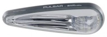
Moreover, Wicks had AeroLEDs in stock… money to be saved! After some more research, and talking with the guys at AeroLEDs, I decided to save almost $200 and nab a pair of Pulsar LED Nav/Strobe/Position lights. Although admittedly these lights aren’t TSO’d right now, they are up for it the near future. And after having seen the statements by the bubbas at AeroLED on the forums, I’m more than comfortable that it will happen before I have this bird finished.
And besides all that, I think they are just really nice looking lights! (oh yeah, lightweight and fairly low current draw as well).
•••
12 December 2013 — Well, ’tis the season, eh? I guess I couldn’t leave well enough on a such a good sale that Wicks was having. After doing a bunch more reading, blog surfing and research, I decided to pull the trigger on a pair of AeroLEDs MicroSun wig wag/taxi/landing lights. Although highly unorthodox in a Long-EZ, I plan on mounting these guys on the wingtips primarily as wig wag lights, then taxi/landing assist lights (I still plan on having one good lightweight nose mounted light for landing).
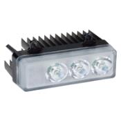
I’ll offer up a few justifications of my purchase here! First, currently when I home in the states I normally fly in the Washington, DC area. Of course DC has some very busy airspace, as does most of the Eastern Seaboard/Mid-Atlantic region. The Long-EZ is of course a small plane with a significantly narrow profile compared to most other GA aircraft. Quite simply, I want wig wag lights because I WANT TO BE SEEN! And as one person noted on a blog (probably VAF), LEDs often tend to be better at getting noticed (seeing the LEDs) then projecting light to actually see what’s in front of them (LED illumination). The AeroLEDs MicroSuns are small, very lightweight, and draw very little power. And they should give off enough light to really help during night landings and taxi ops. Which leads me to point #2:
I like to fly at night. I have ever since I was a kid and flew often at night with my Dad. To me it’s just very peaceful, calm and serene… and I truly enjoy it. I think Dale Martin (another night flying lover) said it best when he noted, “Amazingly enough, airplanes don’t know if they’re flying during the day or at night . . .” (Yes, we all know pilots are the ones that make the mistakes that cause nighttime aviation boo-boos, but I think you understand his point … and mine). Regardless, these will assist both in flight safety at all times and during night flying missions.
My last point of justification is simply this: They were 20% off!!!
•••
30 May 2014 — Well, here it goes. After literally years of wondering, pondering, scheming and hypothesizing as to what I should do for a nose landing light I decided to go with a light that is simple, lightweight, with low power draw … albeit bright. Notice I didn’t say cheap!
I finally decided that I didn’t want to mess around with any contraption, mechanical or electro-mechanical device that would move a light from point A into position B so that it could be used to illuminate the runway. One concern I had with the plans type landing light set-up is that it doesn’t easily allow for incorporating & using wig wag technology . . . not without some drag penalty. Over the years I’ve spoke with a number of builders & EZ drivers on this subject, and there is an overwhelming consensus that our Long-EZs are simply difficult to see in the skies, and that we simply need to be as visible as we can possibly get to enhance safety of flight.
Another concern I had was having a single-use light. I’ve heard many builders, and read many others, discussing having a movable light so that it can be dual-use, serving as both a landing light, then a taxi light. I really didn’t want to mess around with having to adjust my light to use it as either a landing or taxi light, although I wholeheartedly agree that having the capability for both landing and taxi lights is a valid requirement.
My epiphany finally came from Squadron III’s newsletter, sent out by David Orr (AKA “Beagle”). Beagle has a beautiful Berkut and guess what he has on the front of it? Two, small, round beautiful lights! There was my answer! No drop down lights, no mechanical levers to push or pull, no extra switch to flip . . . the answer was so obvious! Just use two small bright lights, and point one at the appropriate angle for landing, and set the other at the right angle for taxiing . . . or close enough to it. I’m not overly concerned about the taxi lighting because I have two taxi/wigwag lights designed into the wings. But by having two small ~2″ lights in the nose it meets all my design criteria: Simple, no moving parts, lightweight, low current draw, minimal drag, and incorporates full-time wig wag capability.
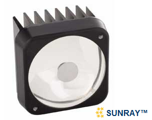
I looked around for a while for an appropriate light to use. Beagle and I spoke and he gave me some pointers, managing heat being one critical aspect of using nose-mounted landing lights. I finally decided to stay with my current exterior lighting brand choice by sticking with AeroLEDs. I ended up buying one of their Sunray Plus LED landing lights. I figure I’ll test it out & if I like it I’ll simply buy another one to use in tandem.
•••
9 June 2014 — I spoke with electronics guru, Eric Jones, from Perihelion Design for a couple of hours a few days ago. Eric is a regular contributor to Bob Nuckolls’ Aeroelectric Connection forum. IMO, two indispensable resources if you’re working your electrical system are Bob Nuckolls’ book, The Aeroelectric Connection, and his forum hosted on the Matt Dralle’s Matronics forums, which covers far more than just electrical systems. My discussion with Eric turned to LED landing/taxi lights, which he is infinitely familiar with. I wanted to see if there was a lower cost LED solution to those sold on Aircraft Spruce, Wicks, etc. Eric recommended the MR16 light, which has many different derivatives, and sent me this specific model pictured below as his recommendation to try out. As you can see in the pic below, it looks very solid with a robust heat sink & cooling air flow design.
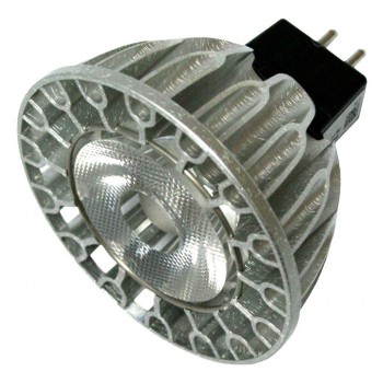
I bought the Soraa MR16, Model # 00235, which is an 11.5-Watt Dimmable LED light. In addition, this MR16 is a 75 Watt bulb equivalent with 3700 Candlepower. It produces a 20° narrow flood beam and looks to be perfect as an ancillary landing/taxi light in the nose along with the AeroLED Sunray Plus LED landing light that I picked up about a week ago. However, at less than $40 off of Amazon, including shipping, it may just work out to be an excellent deal. Of course I will test the light, configurations, etc. before incorporating it into my nose light design, but for now it looks highly promising. I’ll report more on it when I get to that stage of the build.
•••
19 February 2015 — Sorry, but I don’t have any pics to load just yet, but I quickly knocked out a few items on my list that I thought were important to complete in order to establish some data points, one of them being the Landing & Taxi Light Test.
I grabbed my LED landing and taxi lights, and quickly connected them up to a 12V battery to ensure that they all worked, first off, and to also get a good idea of the light strength and beam pattern of each respective light. I have to say that I was quite impressed with the lights and I will definitely move forward with my designed electrical plan for the landing and taxi lights.
I was really impressed with 11.5-Watt Soraa MR16 LED light for use as a taxi light. For only about $38, it really gives off a strong beam, albeit not very concentrated. I think the diffuse pattern will complement the very focused beam of the AeroLEDs Sunray landing light. And I’m still currently planning on mounting both of those in the nose.
•••
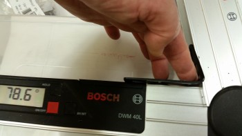
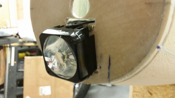
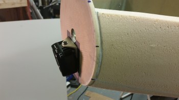
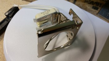
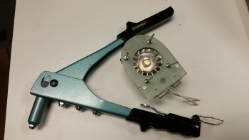
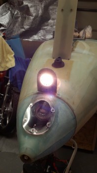
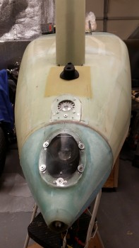
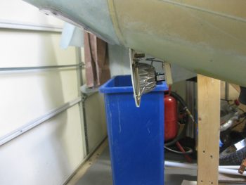
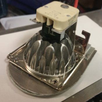
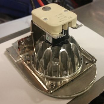
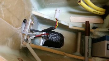
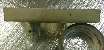
26 December 2015 — Today I messed around with the landing light to get an idea of how to mount it. The landing light is an AeroLED MicroSun light that includes the wig wag feature. I bent the mount (that I bought separately) so that it positioned the light at an 11.4° down angle as shown below:
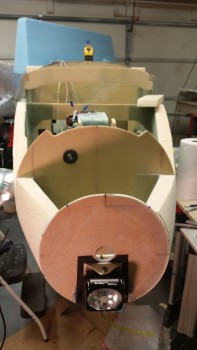
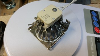
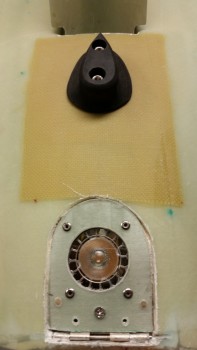
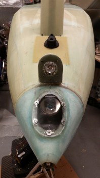
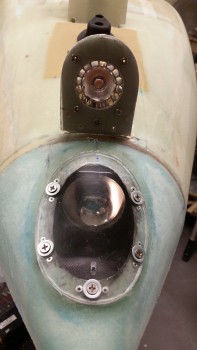
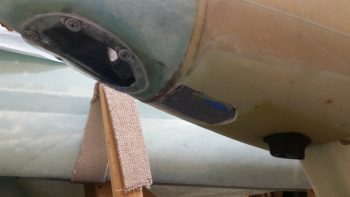
Below is a front view of the landing light installed.
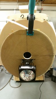
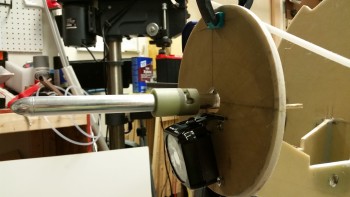
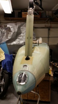
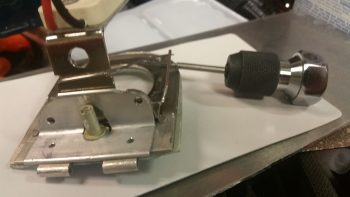
This is the crux of what I was after by messing with the landing light & the pitot tube at this juncture: the clearance & space between the pitot tube and landing light, and of course getting a handle on the wire runs for both of these components.
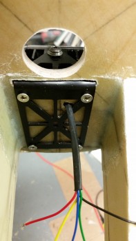
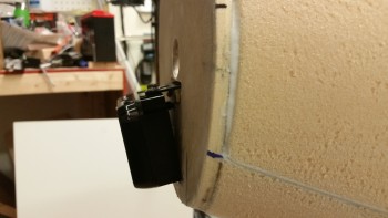
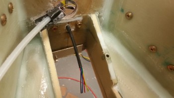
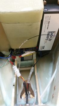
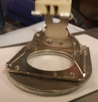
And here’s the aft side of F-7.75 in the batter compartment where the majority of the landing light bracket will reside.
I grabbed a couple of alligator clip wire connectors from upstairs along with an inline 3 amp fuse and quickly fired up both the light and the wig wag feature to ensure all was good with my light (and do some mental night landings!)
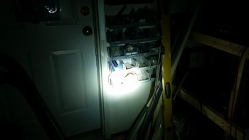
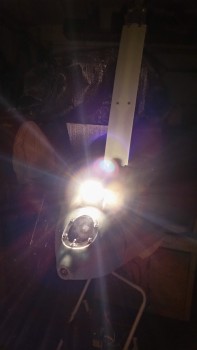
Here’s the beam on the wall about 6-7 feet in front of the nose. As you can see, this beam is very tight, so it will need to be aimed correctly, but will make for a nice landing light. This is just the beginning since I’ll end up having enough lights on this thing to make it look like a UFO!
Here’s a very short video I made showing the landing light’s wig wag feature:
•••
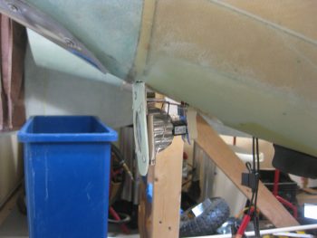
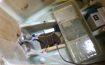
31 December 2015 — Here’s a couple shots of the landing light after I put spacers on between the aft side of the F-7.75 bulkhead and the landing light mount to move the mount, and thus the light, farther aft. If I could move the light up, which I can’t due to the pitot tube G10 sleeve, than this would resolve this issue of the light hanging too low as well. But my only option is to move the light assembly aft, which means the bottom aft corner of the light will have to occupy space that currently is the front face of the F-7.75 bulkhead.
I took my Dremel and grinded a channel that is perhaps about 0.1″ deep where the bottom aft corner of the light would contact the bulkhead. It still needs to go a bit farther back so I’ll continue to mess around with it until I get it dialed in.
•••
1 January 2016 — Today I mounted the landing light for the last time in what I hope will be a very long time! I used a very small dab of blue Loctite on each screw.
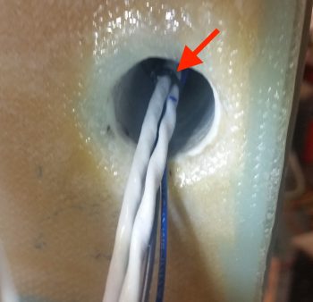
Something that isn’t visible in the pics is that I put 3 layers of heat shrink on the first inch or more of the already covered bundle of wires. Since I couldn’t get a grommet in there with the way the mount was configured, I figured 3 layers should do fairly well. Of course this will be an item that I check on my condition inspections.
One item of note is that when I slid the wires through the new hole I drilled in the bulkhead, it was fairly tight. I think this tight fit in the wood hole should act as a natural grommet keeping the wires secure from vibrating or flopping around.
Here’s a front view of the light. I did a final check on the angle, and it’s sitting right at 13°. Since I have a nose taxi light and will have wing lights too, I’m absolutely happy with 13°. I also pulled out the square and checked each side with the bulkhead… perfect at 90° left & right.
•••
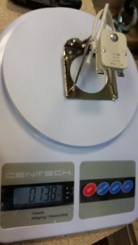
4 January 2016 — I received my mounting bracket for my Taxi Light this morning. It felt a bit hefty so I weighed it. As you can see it weighs in at 0.138 lbs, but I see a number of lightening opportunities so I’ll be thinning it down a bit in a few areas.
Here’s another shot.
And here’s a shot with the actual LED taxi light mounted into the mounting bracket.

And the aft view of the taxi light in its mounting bracket.
•••
22 January 2016 — Although I haven’t terminated the wiring or added the connector, I wanted to show that the landing light is operational. After installing the nutplates on the landing light lens cover mounting flange, I started pulling the tape off the face of the landing light that protected it while it was buried away in the nose foam.
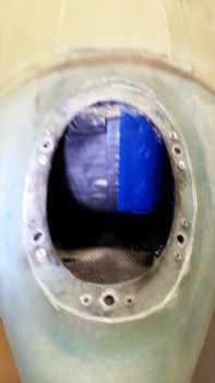
I then mounted the Lexan lens cover to the landing light mounting flange. [You can read more about the specific installation details on the Chapter 13 page.]
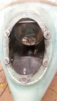
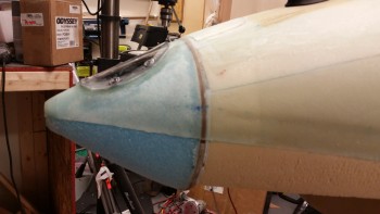
Here’s a side shot of the mounted lens cover.
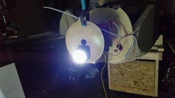
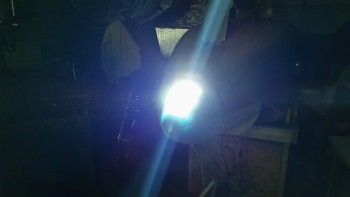
I then fired up the landing light to check out how it’s looking through the lens cover.
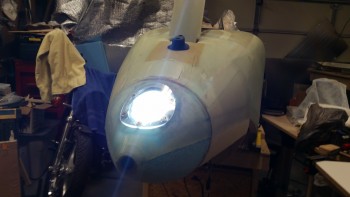
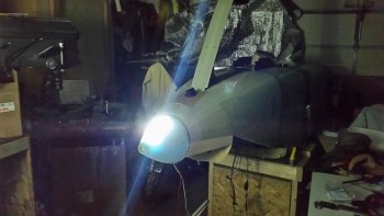
I then turned out the shop lights t see how the light illuminates in pitch dark conditions. Looking good!
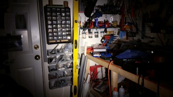
I shot a laser dot out from the pitot tube which hit level with he black handhold that you can see at the bottom of the yellow level in the pic, which tells me that there’s a good difference in angle as there’s supposed to be.
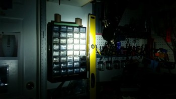
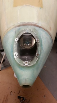
Here’s a closer in shot of the landing light, still with the shop lights off.
•••
25 January 2016 — I started today by exposing the taxi light door/mount hinge from under the nose skin glass & also digging out the foam to allow the taxi light to retract in the nose (see Chapter 13 – Nose & Nose Gear for installation details). I then mounted the Plexiglass lens to the nose taxi light door/mount assembly with silicone RTV. Here’s a shot of the cured silicone RTV-mounted lens cover on the taxi light door/mount.
After a good hour+ cure on the silicone RTV, I then set up to mount the taxi light bulb mounting bracket to the door/mount. Note that I already mounted the two lower outboard flush rivets.
I inserted the Pop Cherry rivets into place in prep for mounting the bulb mounting bracket to the taxi light door/mount.
I then riveted the bulb mounting bracket to the taxi light door/mount. Here’s a shot below with the taxi light assembly in the retracted position. If the light assembly looks a little off center it’s because it is. The assembly sits 0.15″ to the left to allow space on the inside of the battery compartment for the extension hardware. In addition, there’s a very slight offset to the LED bulb bracket as well. In the end, although I would prefer that the taxi light be aligned dead on the CL, it is still completely functional so I’ll live with the slight offset.
And here’s a couple of shots with the taxi light assembly in the down/extended position.
I then hooked up the taxi light to power & fire it up!
I then turned off the shop lights to check it out.
And here’s a shot of the light pattern on the wall. At 20° wide, the taxi light pattern is much more diffuse than the landing light’s 6° pattern, which is of course why this LED bulb makes such a great taxi light.
Of course I had to get a pic with both the taxi light and landing light fired up!
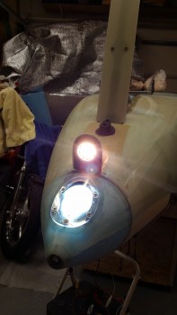
You can see the clear difference between the taxi & landing light beams on the wall, shown in the pic below. Obviously, there is a blue & yellow color difference, but the landing light is also a focused 6° beam angle aimed around 13° down that is optimized to light up the runway in the landing configuration of the Long-EZ on final approach. On the other hand, the taxi light is a more 20° broad beamed light aimed straight ahead when the aircraft is taxiing on the ground which is also optimized for its purpose of ground use.
Here are a couple of shots with the taxi light in the retracted (“stowed”) position.
I’m going to leave the rest of the taxi light install for a later date. I need to put some more thought & R&D into exactly how the mechanism will work to get the light to extend & retract. As you know, I’m trying to link it to the nose gear extension/retraction, but that needs a lot more work & refinement as well. However, since the major installation of the taxi light is complete, I’m happy with leaving the final install actions for later.
•••
9 December 2016 — Today I decided to go ahead and get the landing landing light and taxi light wiring/cabling knocked out.
First up was the landing light. The installation manual for the AeroLEDs Sunray Plus landing light calls for using 20 AWG shielded wiring to power the light. I only had 22 AWG on hand, so I used it since I’m confident that it will work since the actual run is only about 5 ft vs 3-5 longer than that if it was buried out at the end of a wing somewhere in a “typical” install.
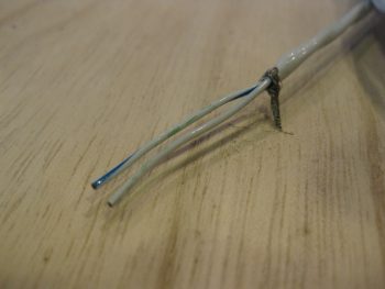
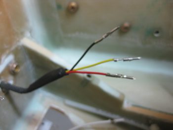
I started by stripping away about 2″ of the outer jacket.
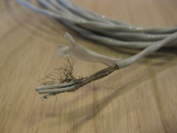
I then wrangled and cut the shielding wire.
And soldered a piece of 22AWG black wire for the ground wire.
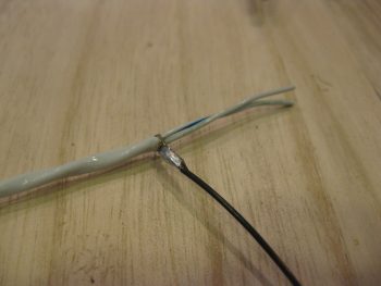
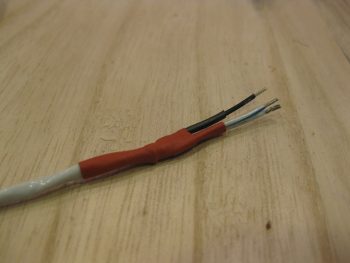
I then heat shrinked it all up: red to symbolize positive power, and black for the negative ground wire.
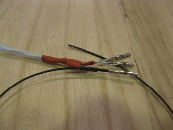
I then terminated the wire ends with mini-Molex socket connectors. Note that the black pigtail wire will actually terminated on a mini ground tabs block that I’ll have mounted onto the negative post of the battery. [Note: Although I’m not a fan of Molex connectors for the larger, multi-pinned connectors, the mini-Molex connectors work just fine for 2-6 wire applications … just my opinion, YMMV].
I then prepped the landing light side. I had 2 extra wires that I simply folded back onto the main cable and heat shrinked in place. I then terminated the remaining 3 active wires (red for light power, black for ground, yellow for wig-wag) with mini-Molex pin connectors.
And then attached the 4-pin mini-Molex connector (J0, A side).
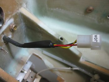
After running the landing light cable through the hole & grommet in Napster, I then connected the J0B side of the landing light connector to the J0A side. Looking good! Note in the pic above and below the white wire leads of the taxi light, those will change in a bit.
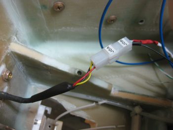
Here’s a long view of the open nose with the landing light wires & J0 connector visible.
I then set to work to terminate and wire up the Taxi Light with a 22 AWG blue wire for power (blue just happens to be the color of the wires used in the Infinity stick grip for that switch, so I carried that color all the way through) and a 22 AWG black wire for ground. Note that I also labeled the wires on the light side, something I didn’t have space to do on the landing light. I finished off the installation using a 2-pin mini-Molex connector (J7) that I bought well over a year ago specifically for the taxi light connection.
•••
10 December 2016 — Today was all about solving one of the last big mysteries concerning my electrical system. How to get the Taxi Light to open & close into position? More precisely perhaps, how to get the taxi light in its swing down bracket to open & close, but then also how to get the light to turn on & off concurrently.
The process was as most when designing something like this: a constant battle of cart-before-horse and chicken-vs-egg arguments. I needed to figure out what hardware was available for use, and bounce those against my defined requirements for the taxi light.
After Marco’s recent visit, and again since this really is one of the last big questions needing answered on my electrical system, we discussed it at length. Upon returning home, Marco sent me a few links to some Arduino-based servos, boards & programming. To be fair, since I’m much more of a Neanderthal than Marco, I wanted something more my style: 2 wires, red & black! ha! (Ya know, simple!)
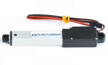
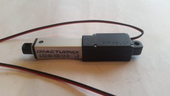
Well, after a couple of hours of on-again, off-again pre-bed late night research, I found a very viable candidate: the Firgelli/Actuonix L12-S Miniature Linear Actuator with limit switches. After figuring out if it would fit in my nose battery compartment area, which it does (barely of course), I then had to decide some specs: speed, torque/force, extension/retraction length, etc. (pic from Robotshop.com).
First off, the -S designation denotes that the actuator arm travels the full length out/in before hitting a limit switch to turn itself off. This was important since it allowed me to simply use an off/off switch, which … hey! I conveniently have one of those on my control stick that’s tagged to control this thing!
Before actually ordering one of these puppies, I pondered and compared the speed and force of the actuator, since those two are in an inverse relationship: as speed goes up, force goes down, and vice versa. The speeds are determined by gearing ratio, with 210:1 being the slowest, then 100:1, and finally 50:1. Again, the speed determines the force. Here’s a very short video of the speed & force difference between these actuators:
I decided to go center of mass with a 100:1 gearing option, giving me about 2.5 seconds opening time for a 30mm (1.18″) stroke actuator. Since I’m limiting the extension of the taxi light to only when the airplane is traveling 70 knots or less, than I figured the 100:1 gearing option will provide a good balance of extension speed & force. If not, I can always swap it out for the slower geared 210:1 version. Of course, my next question was if the 30mm or 50mm stroke was the better option?
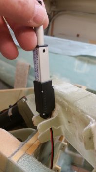
I took a couple of pics of the actual taxi light in its swing-forward position. I’m actually holding it back just slightly aft of its normal resting vertical position with the wire leads. I’ll of course dial in the light position to optimize the light pattern, but this is about where I want the taxi light in its down position.
Another shot showing more of the face of the light.
I then determined and replicated the bottom profile of the nose onto a piece of cardboard, with the -7.7 vertical bulkhead depicted as well. I then crafted an initial cardboard prototype of the bracket that will attach to both the swing-down taxi light assembly, and the actuator arm. I then marked dots 1.18″ aft of the actuator arm attach point and tried a few different positions to see if that was the correct stroke.
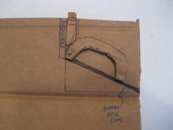
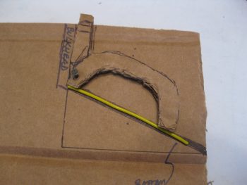
For these pics, I used a scrap piece of yellow 18 ga wire to show the swing-down light assembly positioning. Here the light is retracted flush with the skin of the nose.
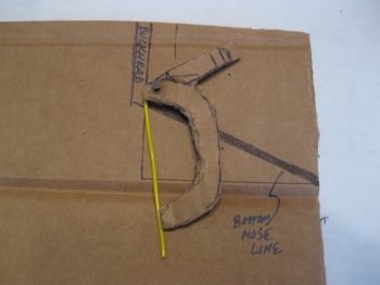
Here’s estimated position #1 for the taxi light position when deployed.
And estimated position #2, if perhaps a more vertical position provides better light projection.
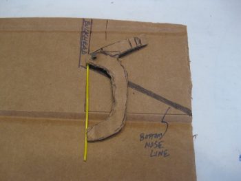
With my mini-test out of the way, I determined that the 30mm (1.18″) stroke is definitely workable. With that, I pulled the trigger and ordered an L12-S miniature linear actuator with limit switches that is geared at 100:1 and has a 30mm (1.18″) stroke.
I then spent a good couple of hours reworking the electrical connection side of installing this actuator via an 8-pin DPDT relay, with the requisite wiring diagram update completed as well.
The taxi light extending/retracting on/off sequence works as follows: Once the actuator moves the taxi light swing-down bracket into the deployed (down) position, it will depress a micro-switch which will then turn on the landing light. Thus, in actuality, the blue Taxi Light switch button on my Infinity control stick ONLY controls the retracting or extending of the taxi light assembly through the L12-S actuator. Completely separate to the actuator circuit, the mechanical opening and closing of the taxi light assembly electrically turns on the taxi light… meaning there is NO electrical connection to the taxi light from the switch on the control stick!
•••
4 January 2017 — Over the holidays I’ve been quietly working on the odd & end aspects of various areas of electrical stuff in my push to get as far as I can on finalizing the electrical system before moving on with the rest of the build.
Yesterday I finalized a 2-day process to figure out the wiring going out to the wing Nav, Strobe & Landing lights. I had a quick but informative discussion with Dean from AeroLEDs and pulled the trigger on a couple different types of shielded 20 AWG electrical wire and some more connectors from Stein. I also assessed & designed a reroute of my com radio antenna cables to get them away from the noisy wing tip light wire runs.
With final decisions made on the wing wiring, I finalized updating my wiring diagram for the Landing/Taxi/Nav/Strobe lights.
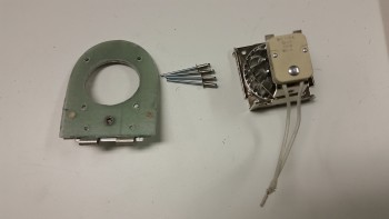
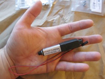
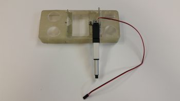
Today I finally received my L12-S mini-actuator for driving the Taxi Light assembly deployment and retraction. As you can see in the pic below I bought a number of ancillary parts that should facilitate the install.
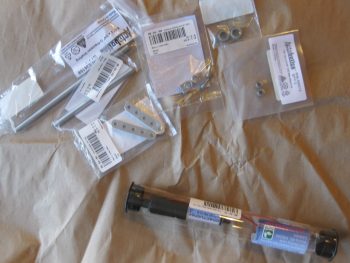
Although I knew it when I ordered it, the tiny size of this actuator is really hard to believe until you actually hold it in your hand, which is exactly what I did! Again, seeing this pic it’s not hard to believe that this thing only weighs 34 grams.
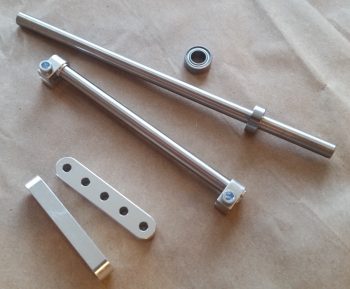
Here’s a shot of the Taxi Light swing down assembly parts that I picked up with the L12-S mini-actuator.
•••
5 January 2017 — Today I performed a final test for the circuit that drives the Firgelli/Actuonix L12-S mini-Actuator for the swing-down Taxi Light assembly in the nose of the aircraft.
I actually set this up last night and messed around with it a bit. Unfortunately, I had one power connection off so it wasn’t working in both directions with a simple ON-OFF switch. For a bit I thought I might need a more esoteric relay along the lines of a latching relay until I found my wiring miscue.
This morning I made the correction and Voila! . . . the actuator worked like a champ with the up/down throw of a simple ON-OFF switch! The ON-OFF switch of course mimics the blue ON-OFF push button located at the bottom front of my Infinity stick grip.
I shot a short video to show how nicely this mini-actuator works, and show a bit of the wiring behind it, including the core part of this circuit: the DPDT relay:
•••
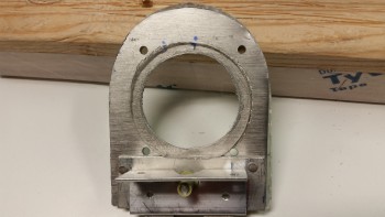
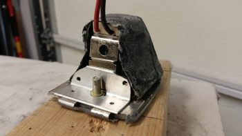
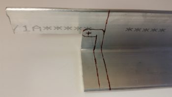
6 April 2017 — Today I removed the swingdown taxi light assembly from the fuselage to work on it in preparation for the final taxi light system install. The first order of business was a long overdue trim of all extraneous metal to get this thing lightened up a bit. I marked the areas to be trimmed in brown Sharpie, as you can see below on the right side . . .
and the left.
Here’s a not-so-great shot of it after I trimmed off the excess metal areas. I also drilled the hole in the aft upright arm a little bigger as well. In all, I trimmed well over 25% of the weight off of this taxi light assembly.
I then drilled and tapped the lower side taxi light bulb frame for two 4-40 screws on each side, to eventually use to keep the taxi light cover mounted.
After reinserting the bulb, I then cut out some cardboard pieces and taped them to the taxi light frame for a mold for the taxi light cover.
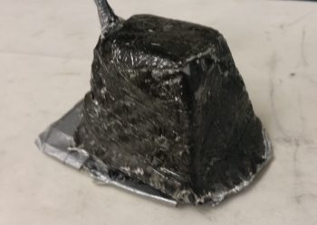
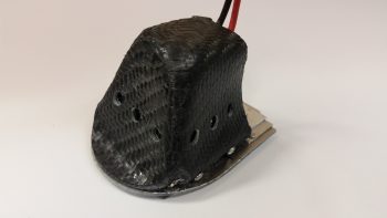
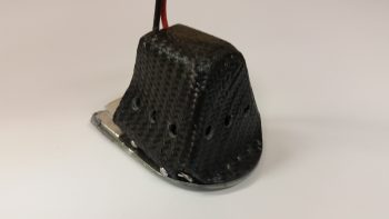
I then prepped 1 ply of BID, 1 ply of UNI (because I have a ton of spare UNI) and 1 ply of carbon fiber in a prepreg setup to layup on the taxi light cover. Well, using prepreg here didn’t work so well, since I didn’t allow enough flex with 3 plies for the sharp corners. Worse yet, the CF started splitting at the tight corners and the whole layup quickly devolved towards sheer calamity.
I ended up pulling the entire layup off the taxi light cover, cutting it into about 5 manageable pieces, and then inverting it so the areas of separated carbon fiber were on the inside of the layup. After placing the disparate pieces of glass in place, I wrapped the whole thing with Saran (plastic) wrap and taped the hell out of all of it. I figured it would require a fair amount of subsequent work, but I wasn’t just about to through all that glass away.
Here’s another shot of my taped “layup from hell!”
•••
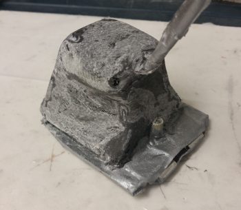
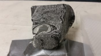
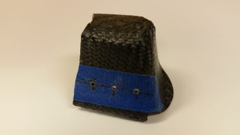
7 April 2017 — Today was the Big Reveal day for the taxi light cover. Since my layup was practicing the truest form of accelerated entropy last night, I simply covered it with Saran wrap and taped it up profusely! This morning I took off the long cross pieces of tape that I used to keep the whole layup from squeezing up the sides of the taped form, really making the cover unusable if it had. I was now at the precipice of finding out what I had underneath of all this tape. Would it be usable? Would have I have to start all over again from square zero?Let’s find out . . .
Ok, so here’s the result in Airdog’s crazy layup experiment emporium. Quite an interesting specimen I’d say, but it really does look usable. As I’ve mentioned many times before, so much of these one-off custom jobs are ITERATIVE processes!
I grabbed my sanding block and my Perm-A-Grit tools and went to town on the taxi light cover. I knew that I would most likely create some holes in this cover to get the shape worked out correctly . . . and I was right. It is interesting that the resulting pics all look quite a bit like snake skin.

Here’s the opposite side. It may be a bit difficult to see, but because I taped the top of the cover down, it resulted in 2 actions: One negative, and one ok. The negative action was that it created “shoulders” on each side of the cover just below the top. My plan was to cut these off and layup a ply of BID that will bridge across the resulting hole. The squashing of the top resulted in the 2nd action, which was that it pushed the sides just below the “shoulders” inboard more…. which was fine and actually allowed for a tighter fitting cover (i.e. takes up less room).
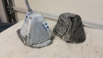
Here’s the sanded taxi light cover next to the taped up taxi light that I used as the cover form.
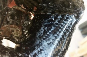
Also, here’s a shot of the inside of the taxi light cover. Aside from scratches from the scribe I used to pry the cover off, the carbon fiber really looks nice. Overall, this pic again has a snakeskin look to it (Marco also pointed this out when he saw it).
After assessing the cover’s usability –including cover mounting & removal– I decided that because the lips on each side clamp around the flanged base of the taxi light bulb mounting assembly, that I it was not practical to keep the forward side of the cover in place. I cut off the forward face of the cover to simply allow the cover to be slid on from the bottom (if it’s deployed/out) or aft (retracted) side of the taxi light. After testing this configuration I could tell immediately that I had made the right call on removing the forward cover side. Much easier!
I then prepped it for more glass (repair layup, if you will . . .) by sanding it to shape. This prep also included using the Fein Saw to remove the right “shoulder” just below the cover top, which left a decent-sized hole in the cover.
I’m jumping ahead here with my pics. The pic below is exactly what I did above, but on the cover’s left side. The yellow epoxy spreader is being employed as a form weight to keep the overhanging glass flat against the side lip. Besides wrapping around the taxi light bulb mounting base to keep the cover securely in place, this side lip will get drilled in 2 places, and be held in place with two 4-40 screws.

•••
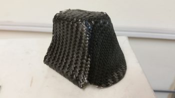
10 April 2017 — I laid up a ply of Carbon Fiber over the left side and aft/bottom side of the taxi light cover. I did get about half of the top as well, so when I do the last Carbon Fiber ply layup, I’ll work to get a nice overlap on the top and a good seam between the aft/bottom side and the right side. One point of note is that the pic below is of the taxi light cover layup after I did a rough cleanup. I need to do a good cleanup of the edges, align sides, etc. before I layup the final ply of Carbon Fiber.
•••
13 April 2017 — After redrilling the 4 holes in the lower taxi light cover to allow me to mount the cover with two 4-40 screws each side, I then spent a good 45 minutes trimming the existing glass and foam in the nose to allow the taxi light to be stowed into the nose side position when it was in its retracted state.
Here’s a good approximation of what the taxi light will look like when it’s deployed with the light turned on. Remember, the taxi light extension and light coming on all happens with the push of one button on my control stick.
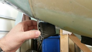
Getting the taxi light nestled back into the nose took a fair bit of trial & error to figure out exactly where the light was snagging on the foam and glass, but after 5-6 rounds of cutting & trimming I was able to get the taxi light –with cover– to seat properly in the hole.
Here’s a shot of what the taxi light looks from the outside. There will need to be a bit of fancy micro finishing work to clean all this up for sure, but I think its well worth it!
•••
19 April 2017 — The first thing I did today was cut out another battery tray lower flange out of G10 Garolite that will be paired up with the existing right flange –with a gap– to make up a composite U-channel for mounting the taxi light mini- actuator.
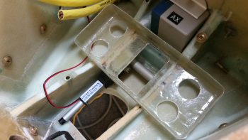
Here’s a quick mockup shot showing how the taxi light mini-actuator will look in relation to the battery tray mounting flanges. [NOTE: To be clear, the battery tray is turned up on its aft side so that my fingers in this pic would be toward the front of the battery compartment].
If you aren’t confused, good! But to show further what I’m talking about here’s a good representative shot showing pretty much how it will look when the mini-actuator is installed onto the battery tray mounting flanges.
[NOTE: For actual battery tray and mini-actuator mounting flange construction, see Chapter 13 – Nose & Nose Gear]
•••
20 April 2017 — Today I drilled and mounted the battery tray mounting flanges for bracket and screw for the mini-actuator.
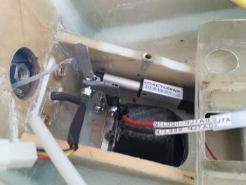
I then mounted the taxi light mini-actuator to the battery tray. Out of curiosity I weighed the entire assembly pictured below and it came out to 2.9 oz.
I then did a test fit with the whole setup in the nose battery compartment.
I had removed the taxi light cover to fill a couple of holes on the lower left side that I had mis-drilled for the mounting screws. Before I remounted it, I sanded out a small rounded half-moon shaped indention on the top aft to provide clearance for the power wires. I then decided, before remounting the taxi light cover, to go ahead and drill the vent holes on each side and the bottom/aft of the cover.
I then drilled 3 vent holes on each side.
To test the initial actuator geometry that I figured out, I cut a test bracket out of a spare big piece of 6061 angle aluminum.
I don’t have any pics, but I messed around with the taxi light actuator and lever configuration for quite a while. Unfortunately, I think my initial 1″ throw estimate for my mini-actuator is about 0.4″ too short. Thus, I have to now start employing brain power –which I really was trying to avoid– to figure out how to implement some sort of mechanical trickery to turn the actuator throw from 1″ into 1.4″.
•••
1 May 2017 — I started off today continuing the work that Marco and I had started on –the P5 connector (stick grip)– and knock out another 5-6 wires.
One of those wires in that connector is the wire that goes from the taxi light switch to the taxi light actuator relay in the nose (RL011). I terminated the wire with a pin and then quickly realized that I was supposed to have TWO (2) wires in that pin terminal: 1) one going to relay RL011 and, 2) another going to the “TAXI LIGHT” LED indicator on my panel.
Being cheap and not wanting to waste a pin terminal, I decided that instead of cutting off the pin and reterminating the wire, that I would simply find the point on the wire that I had just run that was physically closest to where the taxi light ON LED indicator would be located. I then stripped away the insulator on the wire I had just run, cut a new 22AWG brown wire with blue stripe, and solder-spliced it into place.
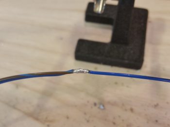
Since these wires both carry positive current, I covered the solder splice joint with a nice long piece of red shrink tube.
•••
2 May 2017 — Today I spent a couple of hours working on the taxi light actuator linkage geometry. I really dialed it in much closer, but still have some stuff to figure out on it. The actuator does a good job moving the taxi light assembly down in place and then back up close to seating back into the hole. With the linkage between the actuator lever and taxi light being variable, it currently doesn’t have enough pull to keep the light up in its bay that last 3/16″. I’m much closer to a solution, so I’ll let this germinate another day or two while I tackle other nose-related stuff.
•••
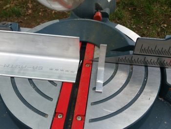
5 May 2017 — Today I decided to focus on getting all the aluminum parts cut that I will need in the near future, and specifically focus on one of the critical completion items on my list before I can move forward with closing up the nose, like the taxi light bits n pieces.
I pulled out the big saw and cut another fresh bracket lever arm piece for the taxi light actuator (shown getting cut below), and a narrow piece of 1/8″ thick 2024 for the other taxi light lever arm.
•••
26 March 2018 — I started off today assessing the configuration of all the hell hole components and the wires in, around and through the hell hole. I did some research on drilling into the CS Spar, knowing that the Spar Caps were sacrosanct, but what about the other areas?
So today I set my sights on getting the wing NAV/Strobe and Wig-Wag lights wiring runs in the most unobtrusive, out-of-site way possible. As I mentioned at the start of this post, I had done a fair amount of research both in the plans, and online, in regards to drilling holes in the CS Spar. The results of my research was of course to stay away from the Spar Caps, no drilling through the shear web (which is actually common for the one hole required for the Autopilot roll servo, if used) and remain clear of the extrusion hard point areas.
I’m not sure exactly what #3 is all about since I have no plans on drilling INTO the hard points, but any viable hole for cable runs is going to be within 2″ of the hard points… and that is “in the area” in my book…. so of the 3 sacred “No-drill” rules I found, I’m apparently violating all the but the spar cap rule.
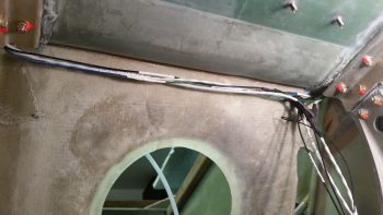
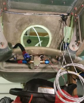
So, in probing around in my hell hole I discovered a spot up in each corner just aft of the CS Spar-GIB seat back intersection where there is sparse glass/flox. It’s actually the lower angled “bull nose” of the CS Spar and that is where I placed my bullseye for drilling a 1/4″ hole diagonally/aft on each side to run my wing lighting wires from hell hole to CS Spar (or vise versa). Here’s the result.
Might I say for my friends in the southern hemisphere: it worked a treat!
I then pulled the wiring out of the hell hole/CS Spar and took it upstairs for further processing (i.e. soldering). I then soldered the left and right CS Spar wing NAV/Strove light wiring together along with the shielded cable run to the light switch on the panel.
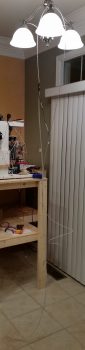
I know it’s fairly difficult to see the wires, but I looped them up over my kitchen light with both sides dangling down just to get an idea of how long the wiring harness is that we’re dealing with here. And this only gets out to the end of the CS Spar. The internal wiring that goes through the actual wings is yet to come!
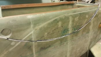
Here’s the completed wiring harness for the wingtip NAV/Strobe lights. It’s late so I stopped on this harness, but I will also have wing tip (or outer wing let’s say) mounted landing/taxiing/wig-wag lights as well, which I still need to make up that harness for. BTW, the left/right CS Spar portion of the wiring is on the left in the pic below, the black ground wire will tie into the “Forest of Tabs” in the hell hole, and the wire bundle on the right goes forward to the switch on the instrument panel.
•••
27 March 2018 — I started off today finishing up the wing lights wiring harness #2 for the wings’ landing, taxi and Wig-Wag lights that will be mounted on the leading edge of the wing anywhere between the end of the wing and the outboard 1/3 of the wing…. with the goal to get them as outboard as possible.
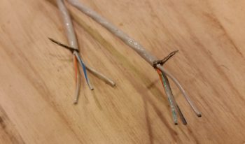
This wiring harness actually involves a 20 AWG 2-wire shielded cable and then 2 external wire runs as well. On the shielded cable, I started by separating the internal wires and tying all the white wires, white/blue wires and the shield from the 3 separate cables: Left wing, Right wing and panel switch/power.
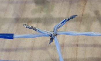 I then soldered spliced the bundled wires.
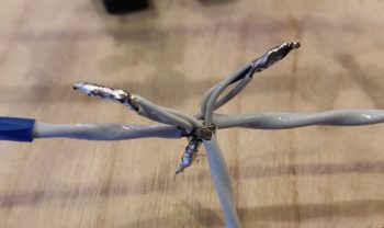
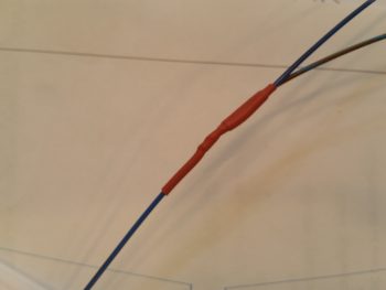
With the cables in a “T” configuration, it made it a bit challenging to heat shrink it all. So I did what I could on each leg, then used flight line tape around the center axis and secured that with some wire lace. Yes, Dr. Frankenstein would be proud, but it is secure!
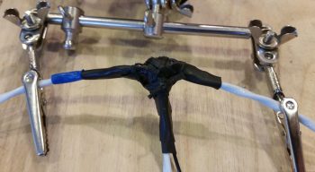
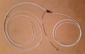
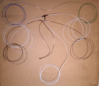
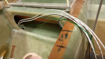
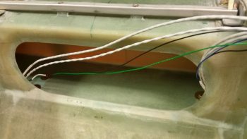
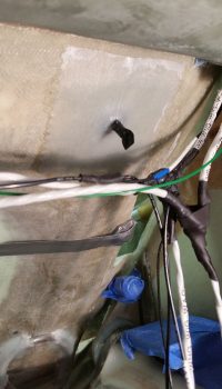
Here’s the end result for the wings landing, taxi and Wig-Wag lights harness. Along the top is a blue (L) and green (R) wig-wag sync control cable, then the shielded 2-wire cable that provides separate power feeds for the taxi/landing light and the Wig-Wag functions. On the lower side you can see a black wire which is of course the ground wire. It shares a ground terminal with the shield ground lead from the 2-wire shielded cable.
I should point out that I had a good in-depth conversation today with AeroLEDs confirming my wiring scheme for all my wing lights, and they confirmed that I was installing them in the best configuration for a Long-EZ.
You may also note from the pic below that I spent a bit of time printing out wire labels and affixing them to the wires, both on this harness and on the Nav/Strobe lights harness I made last night.
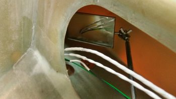
I then grabbed my wiring harnesses and a handful of unattached wiring labels and headed to the shop. I ran the wing wires up through the holes from the hell hole side.
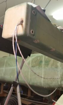
Once the wires were through the holes, I then attached labels for the wires running inside the CS Spar.
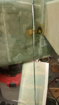
If you look closely, you can make out the wire channel that I drilled through the angled part of the front lower corner of the CS Spar.
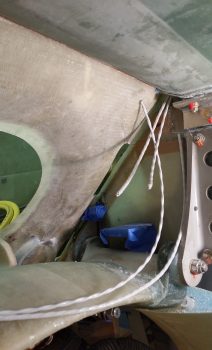
Here’s a Hell Hole shot of the wing lights wiring harnesses from below.
And a taller shot of the wing lights wiring harnesses. The coiled up wires in the lower right of the pic will head forward to the respective light switches on the panel.
 Admittedly, I have a fair bit of slack for the wires exiting out the ends of the CS Spar, especially on the right side. But better to have a little excess than not enough, eh?
With the wing wiring harnesses in place in the hell hole/CS Spar, then came the questions regarding routing and securing. I wanted to ensure the wires were routed in an optimized fashion, to include accounting for the aileron control tube that transits through the Hell Hole.
After assessing and fiddling about with possible wire runs and securing options for a good 20 minutes, I finally decided on securing the wing light wiring harness “T” junctions with an Adel clamp set up high on the aft side of the GIB seat back bulkhead, well over to the right side. Although I had originally planned on keeping the “noisy” wing light wires as far from the “normal” wires as possible, I have accepted why this area has the moniker “the Hell Hole” as there is just not enough space to keep them all separated. What this means in practical terms is that the upper Adel clamp will secure pretty much all the wires entering/exiting the Hell Hole from the sides and above: both the special “noisy” wires and the “normal” wires.
I also added 2 plastic wire tiedown points in the middle and left on the upper seat back. If they look a bit low and askew, well… they are! When I installed them the wire bundle was higher up (read: in the way) and I placed a dab of 5-min glue in the center of each one. Well, as I was installing each one, the angle of the seat got the best of me and the original sticky backed pad on each tiedown point caught the seat just enough to pivot the tiedown forward and set it on permanently where it hit. Yes, this got me on both of the tiedown points… so they sit where they caught the seat! If I screw up, I like to do it twice to confirm that I screwed it up right!! (ha!) Luckily, they aren’t too low and will work fine. Thank goodness they’re in the Hell Hole… don’t tell anybody how crappy they look!
Besides the Clickbond that I bonded/glassed in place high on the seat back for a wire-routing/securing Adel clamp, I also added another RivNut hardpoint a few inches below and outboard (next to the seat access hole) for the same reason. You can see I floxed it in and taped it into place with gray duct tape.
I actually added a third hardpoint with yet another RivNut going straight down in the GIB seat back opening (it’s covered in black electrical tape). This Adel will essentially be the Gatekeeper for all the smaller wiring transiting into and out of the Hell Hole from the forward fuselage. With this setup what I’ve done is stay inline with Bob Nuckoll’s advice of keeping the big power wires separated from the little wires since this Adel sits a good 4-5″ above the big power wires coming from the battery compartment. Of course I will do all I can to maintain this separation the entire length of the fuselage.
•••
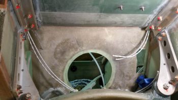
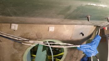
29 March 2018 — I started out today by drilling a hole inside the CS Spar floor down at an angle from outboard to inboard so that the wiring coming up from the Hell Hole would better follow the contour of the side of the oval opening in the CS Spar. My goal is to have the wires accessible and situated just inside the CS Spar oval opening.
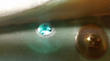
I drilled only through the top layer of glass and then spent almost a half hour digging out as much foam as I could get to, which if you look at the circular empty cavity next to the hole as visible due to a light placed below, it’s roughly the same size as the AN970-4 washer next to it. That’s quite a solid hardpoint considering this foam is 1″ thick [As a point of note I used Divinycell for the spar vs the Urethane called out for in the plans… so slightly heavier spar, but inherently stronger].
I filled this cavity up with about a 60/40 mix of flocro, slightly heavier on the flox, and let it cure before drilling out the hole all the way. In addition, I concurrently laid up a 2-ply BID pad measuring 2″ x 4″ on the underside surface of the CS Spar in the Hell Hole that encircles this hole (I didn’t get a pic of that layup…)
While the stuff above cured, I then pulled the wing lights’ wiring harness back out to wire lace the wires. Once finished I reran the wiring harness through the CS Spar.
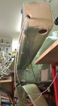
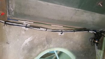
I stopped the wire lacing just shy of each end of the CS Spar (cable lace shown by red arrow).
Here’s the right side wing wiring harness cable laced, draped over the left fuselage side.
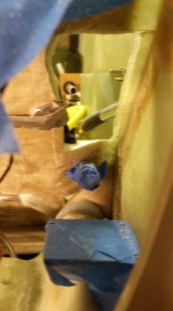
I then cable laced the wing wiring inside the Hell Hole and secured it to the seat back via my plastic wire tie-down points. The loose wire at the top apparently got away from me and at the angle I was working at I simply didn’t see it until I looked at this pic! No worries, I’ll simple secure it as well. I will say that where that loose wire is located is where I was aiming to put the wire tie-down points before the seat “reached out” and grabbed them! Still, the setup works fine and all the wires are nice and secure.
•••