
Chapter 16 – Flight Controls & Armrest Consoles
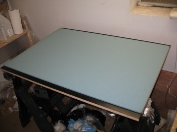
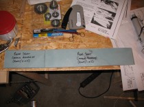
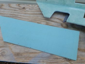
28 June 2012 — I took a bunch of large pieces of scrap BID and laid them out on a FRESH piece of 32″ x 48″ sheet of 3/8″ thick foam. I planned out the layup for the back/inside of the armrests and interior-cockpit consoles and pilot seat back. (I had already created a “cut-sheet” diagram depicting how I would layout and then cut the console pieces from a 32″ x 48″ piece of foam).
I then began the layup of 1-ply BID onto a 32″ x 48″ on a fresh sheet of 3/8″ foam. Since I would be adding different layers of glass, corner tapes, etc, I peel plied the entire sheet.
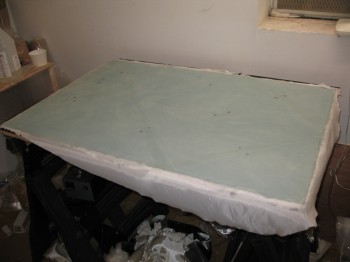
After it cured I knife edged the sides, but left the the peel ply intact.
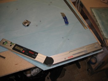
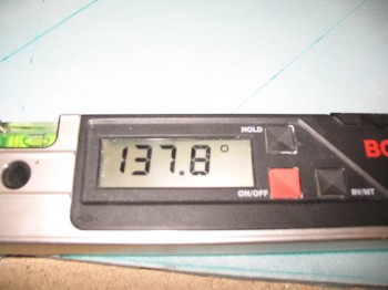
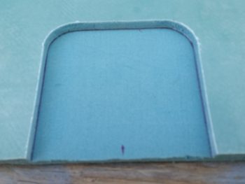
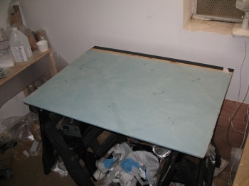 I then marked the Right-side front console & cut it out. I also drew up the Right & Left rear console sides, but before I cut anything out I played around with & tested the angles a bit.
•••
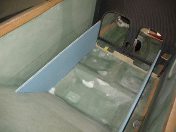
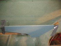
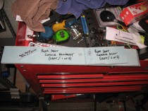
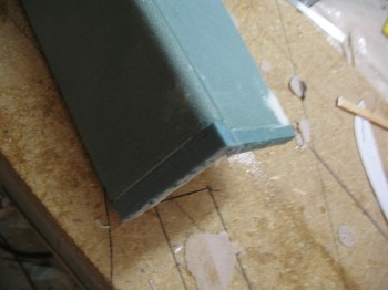
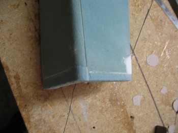
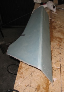
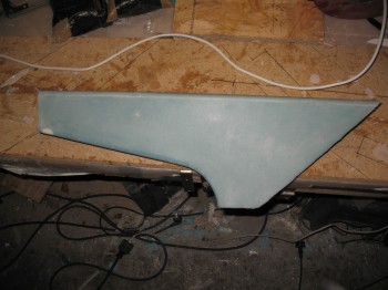
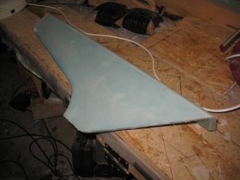
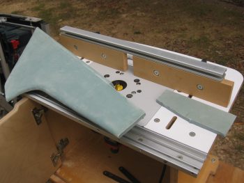
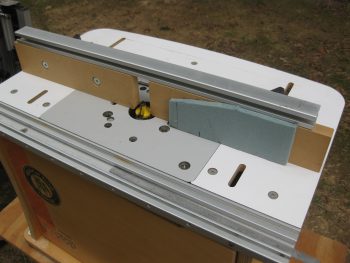
29 June 2012 — I marked the Right-side front console & cut it out from the 3/8″ foam sheet I laid up yesterday. After flipping the fuselage right side up, I took the Right front console out to the garage for a test fit. After a few extra cuts and and a bit of sanding, it fit really well.
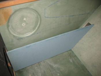
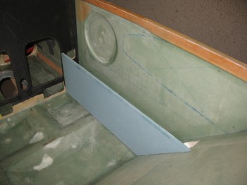
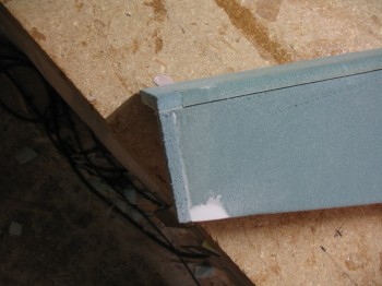
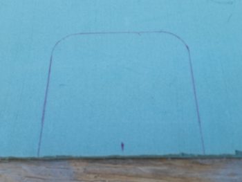
I also drew up the Right rear console side, but before I cut anything out I played around & tested the angles a bit.
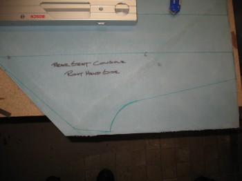
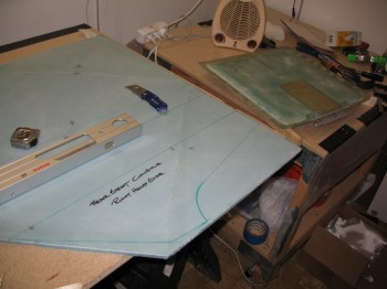
I marked the Right rear console side.
FYI – the Right side consoles are detailed in Chapter 16 while the Left side consoles are detailed out in Chapter 24.
•••
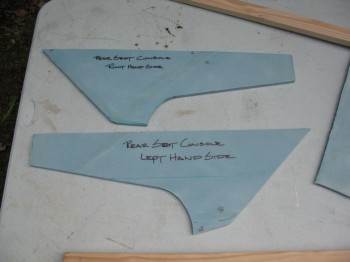
30 June 2012 — I pulled the foldout table outside and cut up the 3/8″ foam sheet into Chapter 16 Right-hand side panels, Chapter 24 Left-hand side panels, and Chapter 8 Rollover structure base (front seat back cap). First, I cut the Left rear console (You may notice that the Left rear console is not per plans. Instead of making it more like a basic triangle, I made it a mirror of the Right rear console).
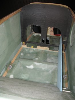
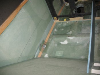
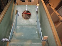
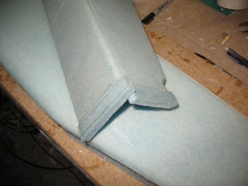
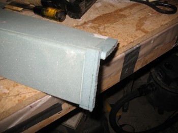
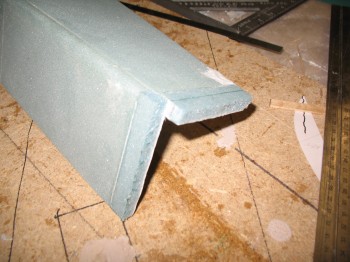
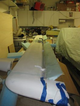
I mocked up the sides of both front seat consoles.
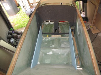
Then I turned my attention to the rear seat consoles. It took a little bit of time fine tuning the angles, mainly between the rear seat back and console junction.
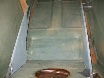
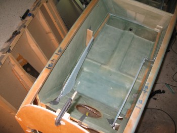
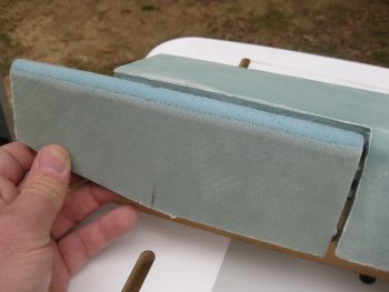
After I got the sides of the consoles fitting decently, I cut the tops and checked out how those fit. Grant it, I had to take into account that their sides are straight and the fuselage walls are curved, so their fit obviously wasn’t exactly like they will be when ready to install.
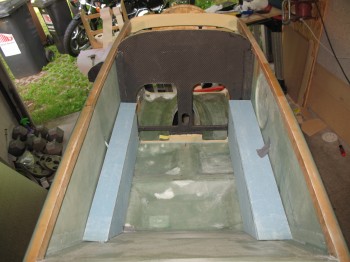
The front console sides are wedged in nice and tight, so mocking up the tops are no problem. However, the rear consoles are jury-rigged in place with tape, so even though I did a cursory check, I didn’t mock them up like I did the front… or take any pics.
•••
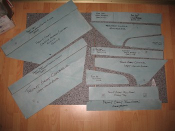
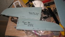
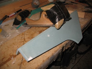
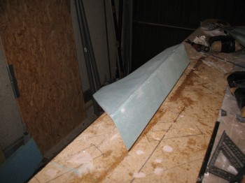
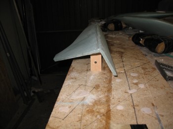
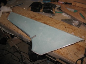
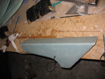
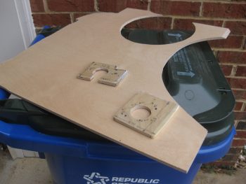
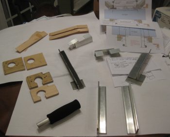
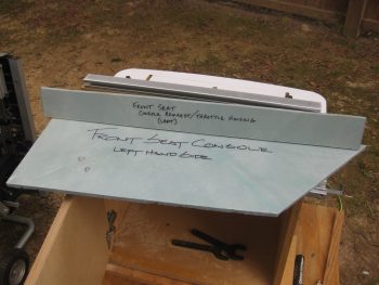
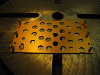
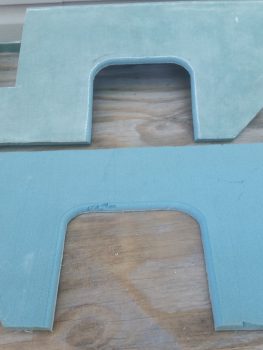
9 July 2012 — I gathered up all the individual parts of the Chapter 16 and 24 consoles, arm rests & front seat ribs for some pics, as shown below:
•••
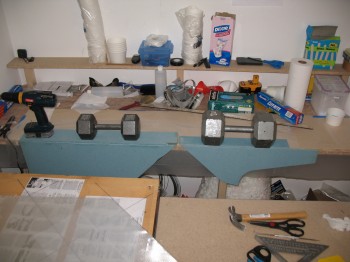
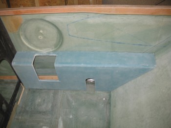
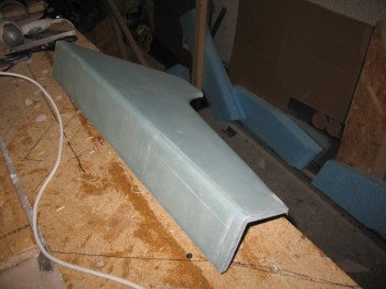
19 July 2012 — I went to work on the fuselage interior consoles (arm rests) in the downstairs shop. On the Right front and the Left & Right rear seat consoles, I mounted the top to the sides with finish nails through the foam. I then pre-pregged about a 1-1/2″ of strip of 1-ply BID and laid it up in the corner along the seam between the tops and the sides of the 3 respective consoles. These will get more glass later when they get installed into the fuselage, so about a 3/4″-1″ overlap on each part will hold it fine.
I used straight fast hardener & let the consoles set for around 15 min, then I turned them right side up and set them on the side of the work bench, held in place with weights so that they would cure at the proper right 90°angle between top and sides.
•••
20 July 2012 — I started the day off focusing on the fuselage consoles. I cleaned up the BID tapes I glassed last night on the consoles/armrests & removed the nails holding the console tops to the sides.
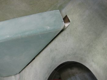
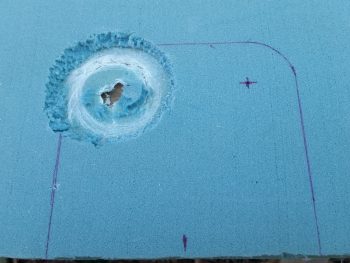
I then took the consoles out to the garage and mocked them up in the fuselage. Again, since the fuselage side is curved and the console side edges are straight, I was just looking for the general look, fit & position of the consoles. That being said, I did take some time to shape the outer edge of the front right console & carve the depression near where the control stick area mates to the side wall/control stick depression. I then rounded over all the corner edges with a 3/8″ router bit.

I cleaned up any left over/excess micro and errant strands of glass on the 3 consoles. I’m waiting to build the front Left console until I nail down the mounting configuration for my throttle quadrant. The final tally on the consoles today is that the Right front & Left rear consoles are ready for exterior glass.
Now, the plans call for simply glassing 2 plies of BID over the entire exterior of the console and overlapping the layup onto the sidewall, fuselage floor, seats, etc. to secure it into place. Since I won’t install these before they get shipped back to the States, I want to provide the foam with a little protection. Thus, I’ll be glassing one ply of BID onto the exterior of the consoles, and then using a 2″ BID tape AND one more entire layer of BID to attach the consoles to the fuselage later on. It will add just a bit more weight, but then I don’t have to worry about my foam getting all dinked up in the upcoming move back stateside.
•••
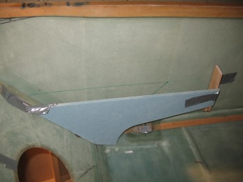
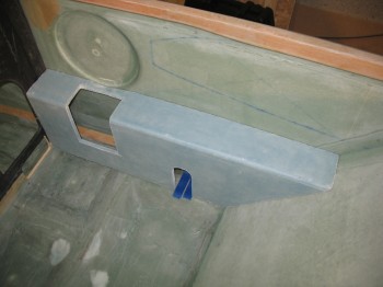
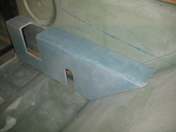
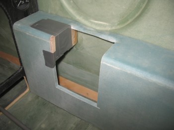
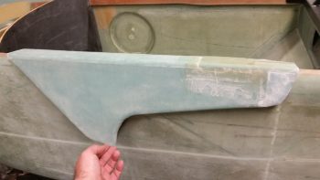
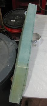
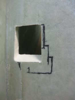
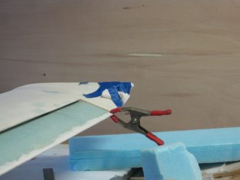
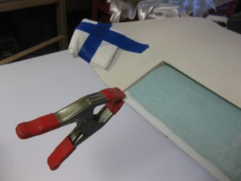
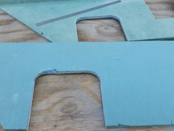
22 July 2012 — I knife trimmed the Right front & Left rear consoles. I marked up the dimensions on the Right front control console, and then cut out the panel for the control stick & seatbelt access (yes, in my haste I cut the seatbelt cutout too narrow, and simply left it to cut wider later on) . . . I also removed the peel ply.
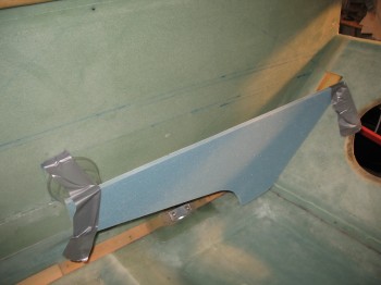
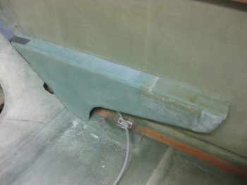
I then took the Right front console out to the fuselage to mock it up & check out how it fit.
•••
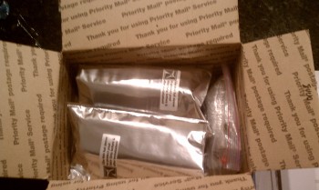
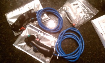
28 January 2013 — After a few discussions with JD Newman, I figured out all my buttons & switches (I think!) and then ordered my Infinity stick grips. Very nice grips! And pre-wired too!
•••
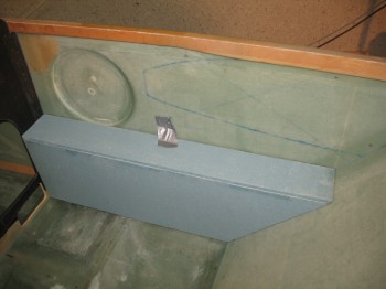
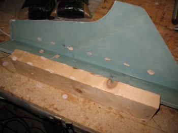
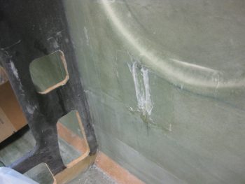
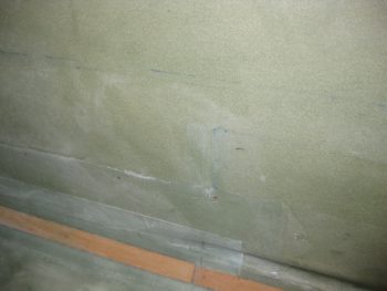
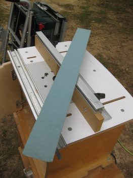
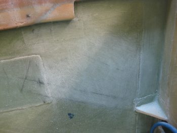
8 June 2013 — As I was working on the lower winglets filling in the TE troughs with micro, I used the leftover micro to add 2 small foam pieces to the front of the Right rear armrest console to extend it just a little bit to meet the plans’ dimensions. For some reason I had cut it too short, so I needed to fix that before I glass the outside surface of the armrest.
•••
9 June 2013 — I measured, marked & cut the foam I had micro’d to the front of the Right rear armrest console.
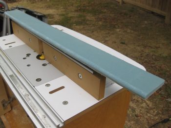
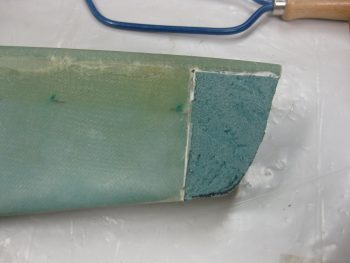
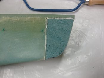
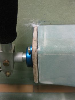
Once I had cut the Rear right armrest to the correct length I shaped the corner by rounding it over to match the existing corner radius. I also radiused the bottom edge of the armrest as well (including the white micro repair patch).
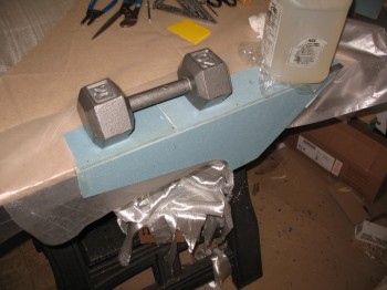
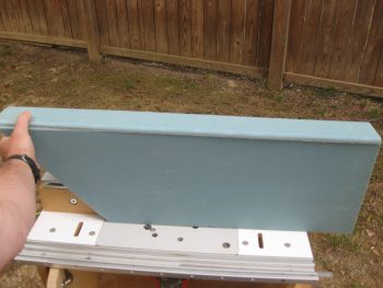
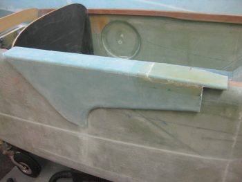
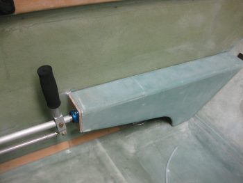
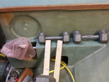
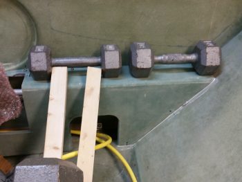
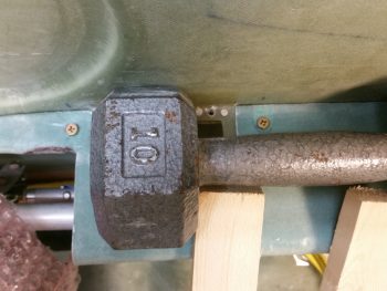
I mounted a 2×4 on the workbench with wood screws and then bondo’d the armrest to the 2×4 to give me a nice solid, elevated surface to glass.
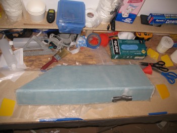
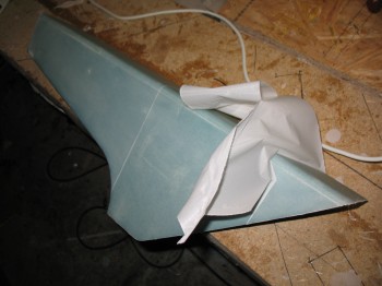
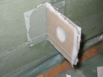
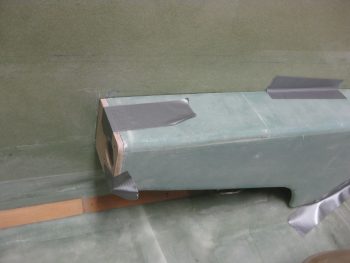
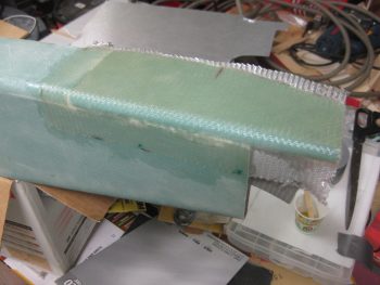
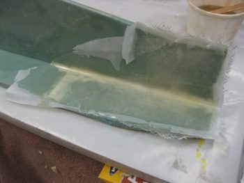
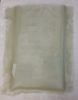
I mixed up some epoxy with fast hardener & made up some thick micro to fill the gaps & dings. I then covered the rest of the armrest foam with micro slurry. Once I was good to go with my micro prep, I glassed the armrest with 1 ply of BID. I of course peel plied it as well (as well as a little duct tape to hold the glass to the foam on the bottom edge radius).
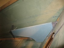
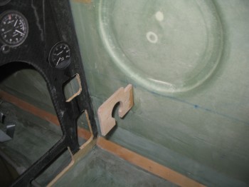
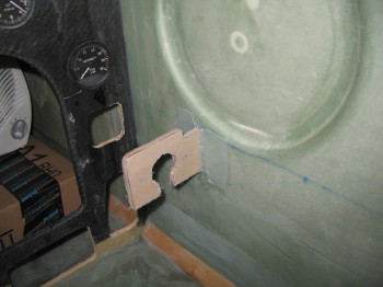
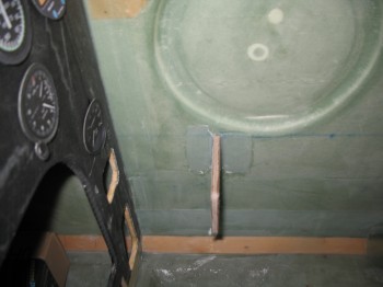
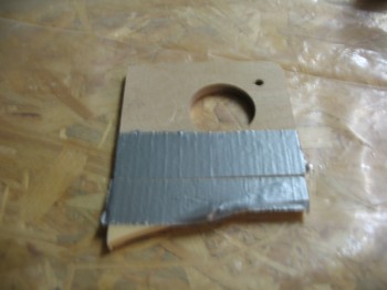
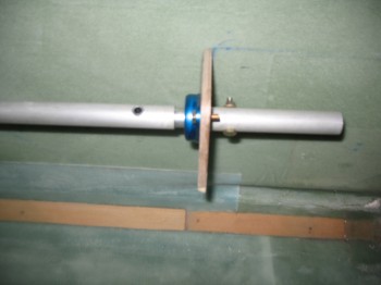
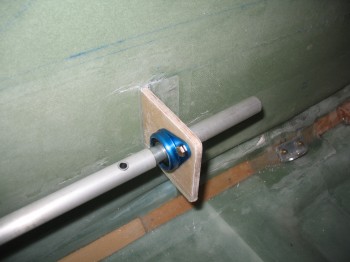
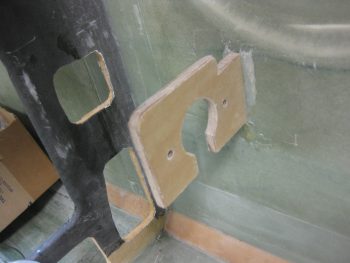
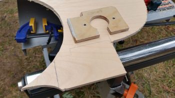
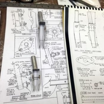
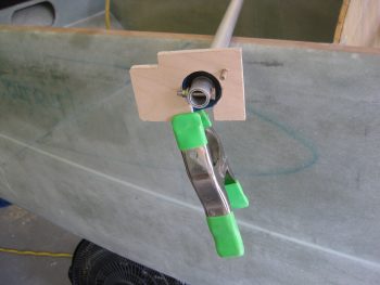
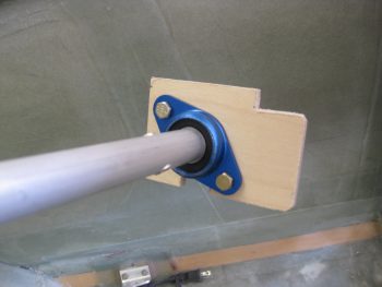
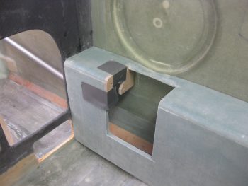
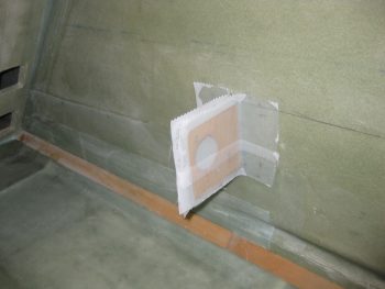
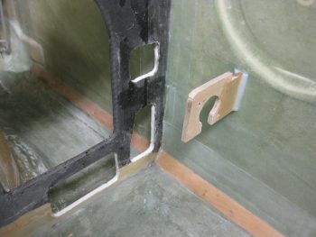
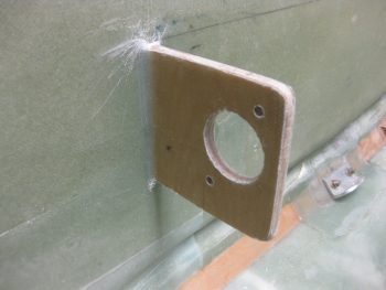
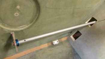
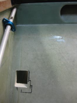
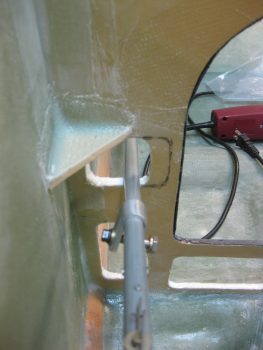
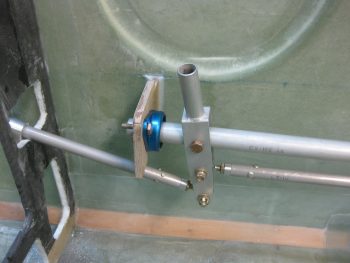
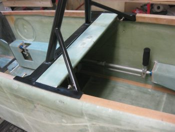
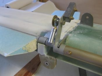
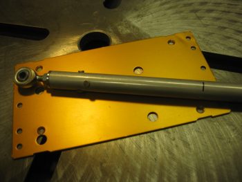
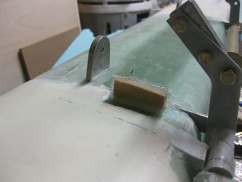
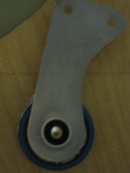
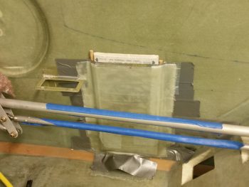
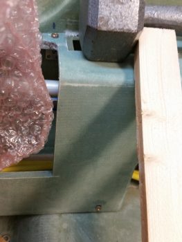
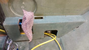
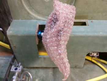
With the Right rear armrest BID layup curing I went to work on installing the front control bracket (CS109) for the flight control grip stick assembly onto the inside Right side of the fuselage. To start I had to mark & drill 2 each #12 holes into CS109 (Birch plywood). I checked the fit of the 2 bolts that will attach the control bearing assembly to CS109.
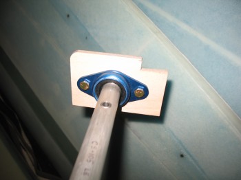
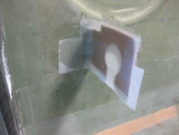
I then taped the control rod/bearing/CS109 assembly in position onto the Right front armrest console. Once I was sure that it was positioned correctly, I 5-min glued the edge of JUST the CS109 bracket to the Right interior fuselage wall.
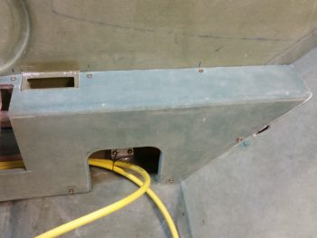
I waited a little while (admittedly more than 5 minutes!) & then removed the tape and the Right front console, leaving behind just the now attached CS109 control assembly bracket.
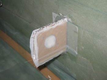
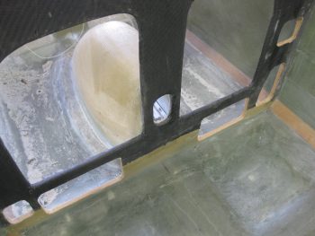
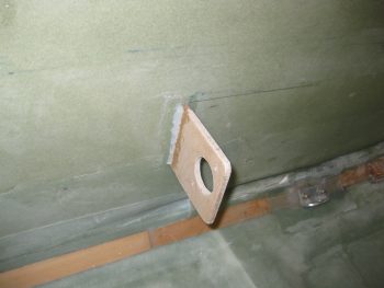
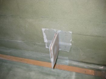
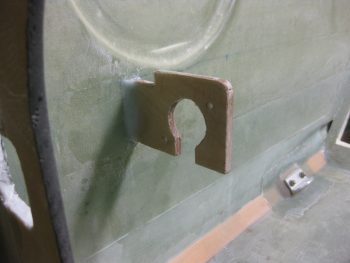
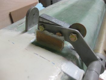
I then floxed filleted the corner between the CS109 bracket & the fuselage sidewall on both the fore & aft side of CS109. I glassed a 1-ply BID layup on each side of CS109 that overlapped about 1 inch onto the fuselage side wall, and then peel plied the layup on each side of CS109 as well.
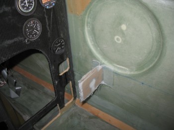
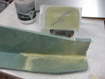
While the CS109 bracket layup cured I returned to the garage to check on my Right rear armrest layup. It looked good & cured enough that I could remove the duct tape. I did, however, leave the peel ply on (I learned that lesson of removing peel ply too soon on my NG30!).
[Also, remember I peel plied the entire surface because per plans the armrests simply get installed into the fuselage with 2 plies of BID overlapping 1 inch onto the fuselage sidewall. However, since I’m not mounting these right now & don’t want them to get tore up in the move, I’m glassing only 1 ply now. Then later I’ll layup a corner BID tape & another full ply of BID when I do a final glass of the armrests into place.]
I then went back to check on my CS109 bracket. I checked the layup and it was nearly completely cured (I used fast hardener) so I razor trimmed the bracket & fuselage side wall.
•••
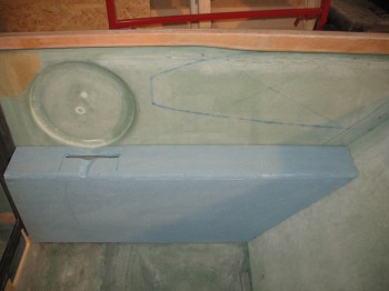
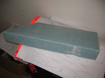
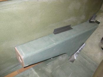
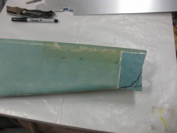
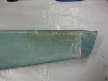
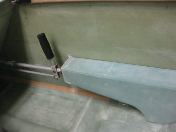
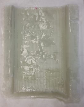
10 June 2013 — I really didn’t do too much today since I was busy prepping for my upcoming move. I started out finishing up on the Right rear armrest console. I razor trimmed & sanded the edges, and then I pulled the peel ply.
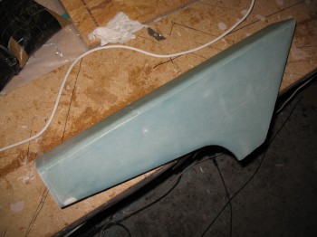
After I pulled the peel ply off I inspected the layup. It looked pretty good & I was happy with my repair actions.
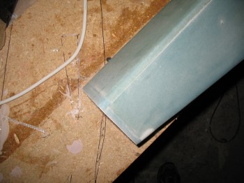
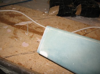
Since it all looked good, I went ahead and popped the armrest off its 2×4 wood perch.
Clearly I had a few bondo blobs to clean up.
•••
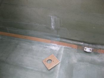
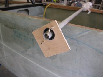
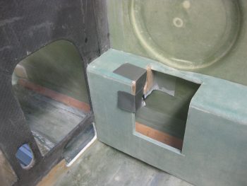
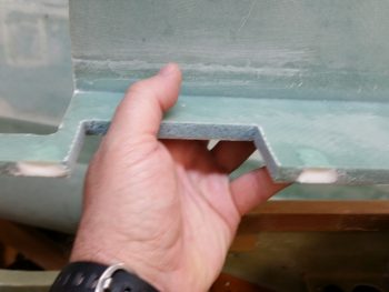
12 June 2013 — I have no idea where my brain was when I initially worked out my dimensions for my Right rear armrest console configuration, but somehow I even managed to come up short on my rear control system mounting bracket (CS118). The CS118 attaches to the front of the rear Right armrest & has a hole in it (like the front attach point) that allows the aileron control tube bearing assembly to be mounted to the bracket with the actual control tube traversing through the mounting bracket, behind/under the Right rear armrest as it travels on its way back to the firewall. Thus, due to my apparent inability to measure anything correctly that day I had to add to its height. I had some Birch plywood that would have worked, but since it was just about 1/4″ that needed adding I used H250 foam to make it lighter.
When I mixed up the flox for installing the Davenport leaf spring attach tube, I also made up enough to attach this H250 foam extension to CS118.
•••
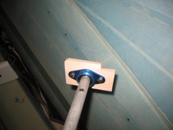
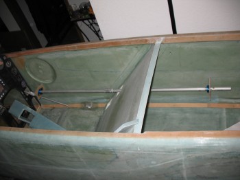
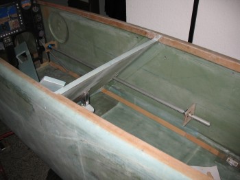
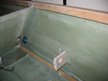
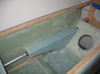
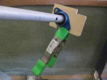
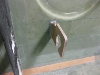
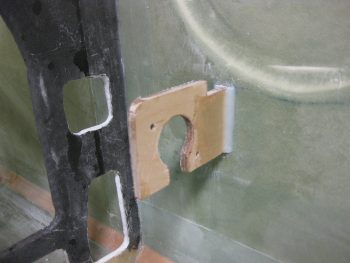
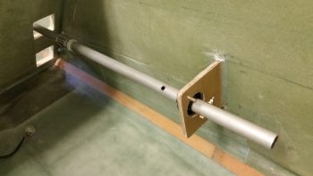
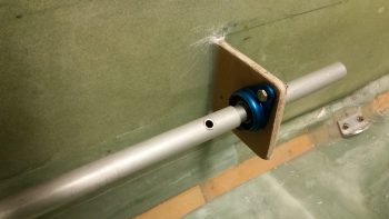
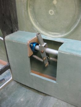
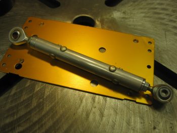
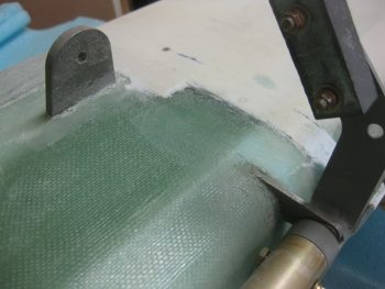
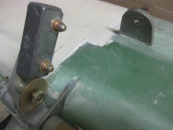
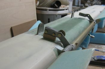
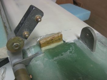
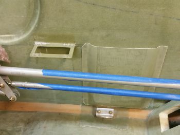
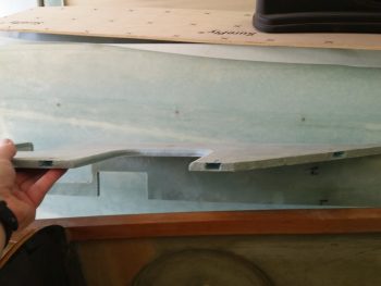
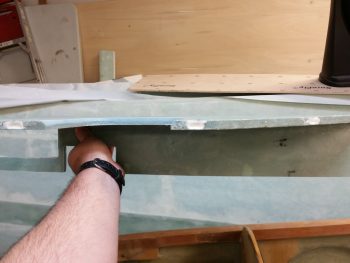
13 June 2013 — I started today by temporarily mounting the Right rear armrest console with tape. In addition, I mocked up the rear control tube mounting bracket (CS118) to both the rear armrest & the right Rear fuselage sidewall.
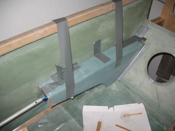
Also, the control tube was mounted into place at the forward control system mounting bracket (CS109).
I had to recut the front of the Right rear armrest console in the tried & true mount-cut-remount-repeat process that is commonplace in building a Long-EZ. I also had to slightly reshape the side of the rear armrest with the sanding block to get the fit locked in as close to perfect as possible, as well as getting the CS118 as close to 90° to the fuselage sidewall as possible. Once it was all looking good & the fit was locked in, I 5-min glued the edge of CS118 bracket to the fuselage like I did previously in mounting the front CS109 bracket.
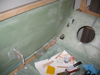
After the 5-min glue cured, I pulled off the duct tape-mounted rear armrest.
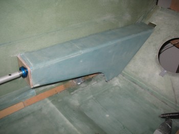
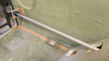
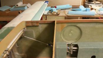
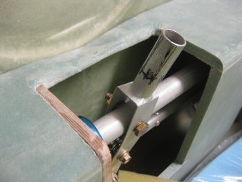
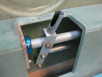
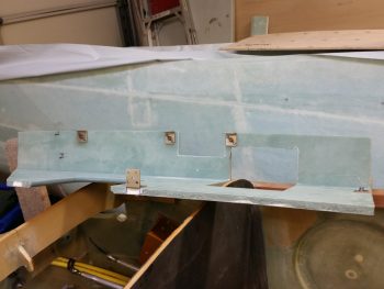
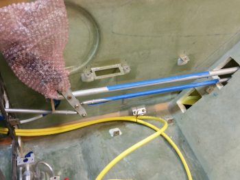
Here’s a couple shots of the initial barebones control system.
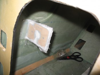
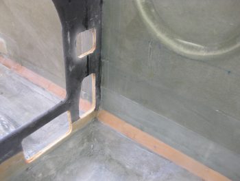
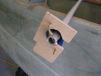
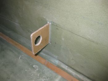
As I did with the foreward CS109 bracket I floxed in a small fillet in the corner between the CS118 bracket & the fuselage sidewall on both the front & back side of CS118 for a nice glass transition. I then glassed a 1-ply BID layup on each side of the CS118 bracket overlapping about 1 inch onto the Right fuselage sidewall. I then of course peel plied the BID layup on both the fore & aft side of CS118 & fuselage sidewall.
[I just wanted to add a quick note on my quality assurance during the layups here in these posts. As I post these pictures I notice a number of them show peel ply with a number of dry splotches in the layup. I just want to say that I’m sure like most builders, after the pics are snapped I go back over & over (some what obsessively often times) my layups to make sure they’re as close to perfect as possible, especially in getting that balance between having just enough epoxy to wet out the glass, but not having too much epoxy either. I just wanted to clarify that a time gap often exists between the point a lot these pics are taken compared to the actual end of my layup efforts, and that while I’m trying to finish my Long-EZ in fairly quick fashion, quantity does not win out over quality.]
•••
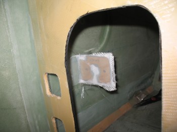
14 June 2013 — Today I started out by knife trimming the CS118 control system mounting bracket. I then pulled the peel ply, sanded the edges, and cleaned up the peel ply goobers & glass. I then redrilled the #12 holes through the glass so I could reinsert the control system tube & bearing assembly. The control tube fit between the aft CS118 bracket & the front CS109 bracket seemed pert near perfect.
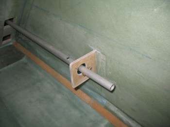
I then reinstalled the Right rear armrest to test fit & finish. It too seemed to fit just right.
As it’s finally acting like Summer here in Germany, it brings with it something we’re normally not unaccustomed to in the States: very late sunsets. Here’s the sun setting last night at around 1030 pm while I was out on my back patio updating my builder’s log.
•••
17 April 2015 — The other night I was on the computer when my Spidey sense started tingling, and I started poking around eBay for throttle handles & quadrants. For some reason I was off on a mental tangent concerning my throttle handle since, if you recall, in early 2013 in response from a discussion with my buddy Marco, I found a source for some F-16 throttle handles for us. We both like the thought of HOTAS (Hands On Throttle And Stick), and an F-16 throttle handle, besides being cool, obviously offered a way of putting switches on the throttle.
Fast forward a couple of years, with both F-16 throttle & fuselage in hand, I started realizing that the Long-EZ cockpit is just not that big. Obviously, the F-16 doesn’t have a lot of real estate either, but the Long-EZ specifically has a narrow left-side console & there’s just not a lot of room for a larger throttle handle taking up a lot space in that area. In addition, the F-16 throttle handle sticks out over the pilot’s leg, which I could see getting in the way during ingress & egress to the bird.
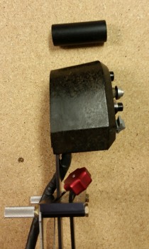
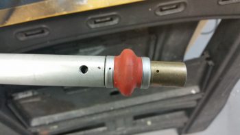
Now, back to my foray on eBay. I was actually looking for an F-100 style throttle handle, and found a couple when I searched for “throttle quadrants.” If you haven’t seen an F-100 throttle handle, it’s rather cylindrical with just 3 buttons on the top. I was actually thinking of incorporating that style into a new design, and maybe work with Marco to build a unique one out of some lightweight 2024 aluminum. But right before I logged off eBay, I searched for “throttle handle” and found a military surplus F-15 throttle handle for sale. It was $69 and seemed to be in pretty good shape (pics below). I did some quick research & felt it was a good deal, so I pulled the trigger.
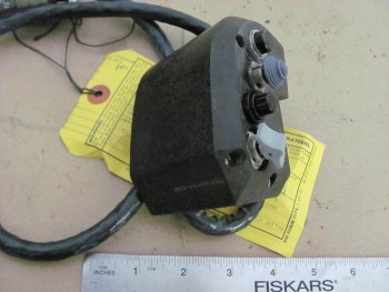
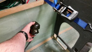
Once I received it a couple of days later, I pulled it out of the box and quickly checked the size & fit in the cockpit. The first thing that struck me was the great fit of the throttle handle in the Long-EZ’s fuselage since the throttle handle’s outboard side is completely flat vertically. This is of course because technically this is just half, or one of, the F-15’s throttle handle assembly.
Since the F-15 has two engines, this is actually the right-hand engine’s throttle handle and is located next to the left engine’s throttle handle in the F-15. If I remember correctly (I supported F-15’s years ago at Langley AFB), they are typically physically paired so they move in unison, thus their mating edges are completely flat . . . which again works perfectly in a Long-EZ!
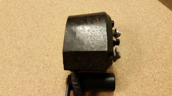
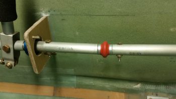
Curiosity got the best of me so I pulled out the existing throttle quadrant and laid the new F-15 throttle handle next to it. As you can see from the pic below, the new handle is only slightly wider the existing black plastic tube handle only because of the switches mounted on the side of the F-15 throttle handle.
BTW, the cost of those aviation grade switches alone was a big factor in my thoughts on this being a great deal. Unfortunately, as you can also see in the pics, I’ll have to spend some time on cleaning up the surface of the new handle too if I want to improve its curb appeal (which I will).
Now, every once in a while when I’m off on one my quests to incorporate some unique “unauthorized” modification to my Long-EZ, and am way, way off the path of approved build actions, I actually get a break. Not just a break, a BIG break that makes something really EZ to incorporate into the design. Thus, was the case with this throttle handle.
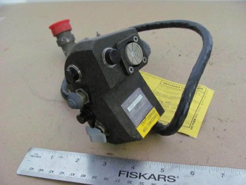
Remember, I had originally just opened the box to ensure that what I had purchased was correct and undamaged. But after checking the size & fit in the cockpit (GOOD!) and the initial size & fit on the throttle quadrant (GOOD!), I noticed the throttle handle had 3 threaded attach points on the outboard (flat) side of the handle. These 3 points all were threaded for AN3 (3/16″) bolts, which is exactly what was used to hold the black tubular handle on the the throttle quadrant that I have (AWESOME!)
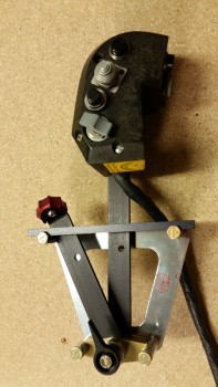
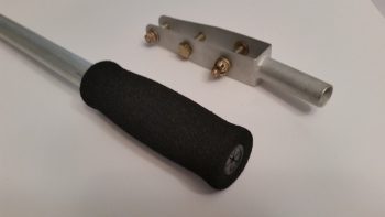
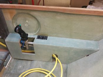
I quickly took off the existing tubular throttle handle and within mere minutes had the new F-15 throttle handle MOUNTED to the throttle quadrant. Clearly I’ll have to drill a second hole to finalize the installation, but that will be all that’s required to physically mount this throttle handle. Of course I will have to contend with routing the wiring as well, but I don’t see that as terribly difficult.
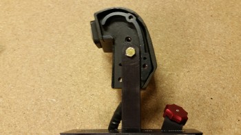
One important note on fit: you’ll notice that with the attach point of the throttle quadrant lever being located close the center of the new throttle handle, the overall space used to employ this throttle handle in the cockpit is quite negligible. It literally just adds a hair more aft of the original handle, a little over an inch to the front, and the vast difference in height between old & new is minimized by mounting the new handle “low.” Thus, there’s really only a true height increase of the throttle quadrant by about 1.5″.
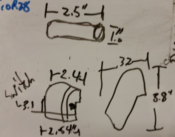
In fact, I keep a small whiteboard on the door of my shop for taking notes, listing glass cut schedules, etc. and I use it constantly throughout my build sessions. I don’t usually show my chicken scratchings on this blog, but here are the size differences I noted between the two throttle handles:
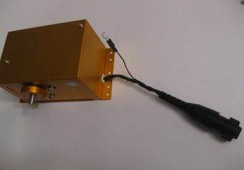
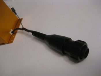
With my NEW throttle QUADRANT assembly in hand, I then checked to see how it looked & fit in the cockpit. In my opinion, it fits like a glove & is exactly what I was looking for… I couldn’t be happier!
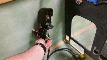
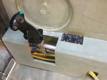
Here’s a side view of the freshly mounted throttle handle.
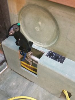
And a view from front looking aft:
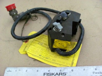
I snapped a few shot to show the size comparison between the old throttle handle & the new one (note the old handle resting on the new one).
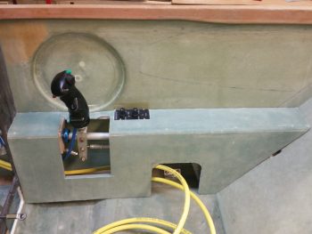
And an aft view.
 As you can see, the new F-15 throttle handle fits much better than my existing F-16 throttle handle (I guess I actually didn’t show the F-16 handle, so I’ll try to get a pic of that in a future blog post). It’s a little ironic, because as I mentioned before I actually worked on & supported F-15s while in the Air Force, and although I was trained on F-16s, I was never stationed where I was in direct support of them.
Another point in this handle blowing the F-16 handle out of the contest, is clearly this handle comes with switches mounted! That makes the task of identifying and employing switches for the landing brake, PTT, COM flip-flop, etc. much easier. Over the next week, I’ll be identifying the wiring schema for the throttle handle, and figuring out how the handle-mounted switches will be incorporated into the overall electrical system plan.
A quick clerical note, I’ll be posting this both in the Chapter 16 (Controls) & Chapter 23 (Engine) build log sections of this site (the original F-16 throttle handle posts were listed only in the engine chapter).
•••
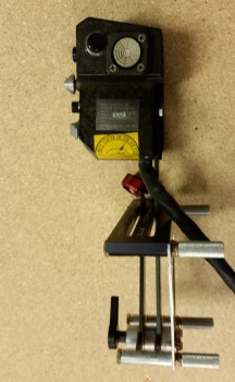
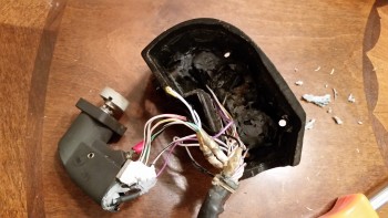
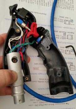
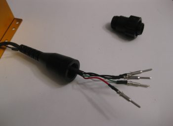
19 April 2015 — My original thought when I acquired my new F-15 throttle handle was to simply test all the individual pins & create a wire map of all the switch circuits. Well, with a 37-pin cannon plug, that was a little easier in thought than in practice. After hunting & pecking for a while, I decided that it was time to dissect the throttle handle and see what exactly I was dealing with . . . and I’m glad I did.
I had already made up a pin-out diagram for the cannon plug & numbered each pin. Since I wasn’t able to figure out the circuits for the switches or visually see them, I clearly wouldn’t know their functioning until I cracked this thing open.
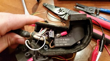
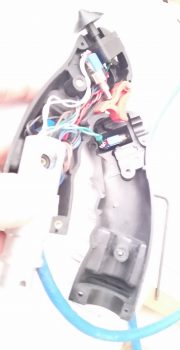
The first thing I saw when I opened the throttle handle up was the flat joystick-style switch that sits on the outboard, front side of the throttle handle. It took me a while to carefully dig out the potting material & get the wires situated to the point that I could finagle this thing out of there. It was a very tight fit!
I then began digging out the other top switch from its potting goop. I identified the wires & listed them by color on another sheet of paper. I set about confirming their connections by performing a continuity check by placing one side of my test lead on a switch terminal, then at the cannon plug side I would simply swirl the test lead around until the voltmeter rang out. Then I would annotate it on my diagram.
After I finished the top switch & had all its info documented, I would then spend another 20 minutes or so excavating the next switch from its potting material prison. Once its leads were exposed, I again performed a continuity check to figure out the cannon plug pins.
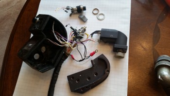
After determining the wiring schema for all the switches on the throttle handle, I discovered some key pieces of information:
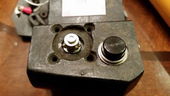
a. I am going to completely rewire the switches in this throttle handle. Clearly these switches are configured for specific discreet electrical components on the F-15, as evident by the myriad of capacitors, resistors, etc. hanging all over each switch. Plus, there is far more extra capacity with a 37-pin cannon plug than I am going to need to drive my components with the switches on hand. My initial thought is that even a 23-pin plug will give me plenty of future scalability.
b. I’ll be removing the pistol-shaped switch that engulfs the entire interior left side of the throttle handle. It may provide more capability when linked to specific F-15 systems, but in my case it only offers me a single-position momentary on. It takes up a lot of real estate and it’s heavy, accounting for almost 20% of the current weight of this handle. If I get rid of this switch by replacing it with a nearly externally identical Otto switch (with much smaller internal guts), reduce my throttle handle wiring harness by nearly half the wires, and use a smaller plastic AMP connector, I think I could reduce the weight of this handle by about half (about 0.65 lbs).
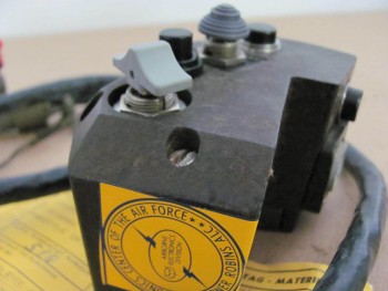
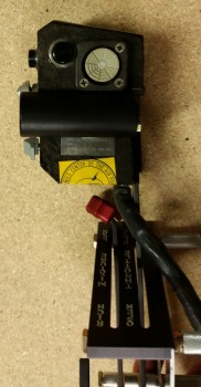
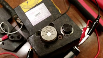
For those of you that are curious about the current throttle handle switch functions, they are listed below this pic in order starting at the top right-hand switch (flat grey) moving CCW.
1. Grey flat joystick style: single momentary on (TBD).
2. Black push button: PTT – single momentary on.
3. Black push button: single momentary on (GTN650 remote or Trio AP fuel data)
4. Metal china-hat toggle: ON-OFF-ON (possibly air brake)
5. Black push button: DPDT dual momentary on (TBD).
6. Grey-capped toggle: 3-position (broken lead/functioning TBD… ON-OFF-ON?)
_________________________________________________________________________
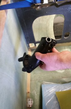
Also, as I mentioned in my last post, for those of you that are curious about the size & fit of the F-16 throttle handle, I shot a couple pics to show what I was talking about.
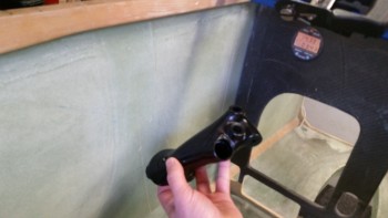
Not terrible at all, but definitely takes up more space than I’d like it to inside the Long-EZ cockpit.
•••
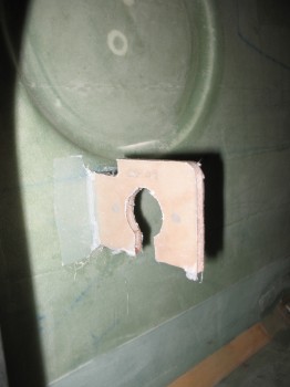
12 September 2016 — Since I had my Fein saw and was using it today, I chose to start to finalize another thing on my bucket list: the CS109 control stick tab. The problem with this tab simply has its roots in the fact that I bought the control system from the Cozy Girls. This isn’t to say anything bad about their components, because they’re awesome. The problem is that their stick mount straddles the round control stick tube while the old control stick setup sits on the inboard side of it, or shall I say 3/4″ inboard of the Cozy Girrrls stick setup.
My buddy & fellow EZ builder Dave Berenholtz points this out on his blog. I took heed after a discussion with him, and will be remounting a new one further inboard which will provide a bit more clearance for the Cozy Girrrls’ control stick between the stick and the immovable fuselage side wall. Since the back seat area was a bit cluttered, I’ll get to CS118 later. For now though I know it will be a 3 minute job to remove CS118.
•••
20 September 2016 — Today I finally got around to removing the CS118 plate in the back seat in prep for moving the control stick mount just a hair inboard! It took less than a minute to remove CS118 using the Fein saw (amazing in comparison to how long it took to glass on there!)
•••
29 September 2016 — Today I made a huge design departure on my aircraft where the GIB control stick is concerned, which I’m very grateful that I made the discovery on how exactly it works back there. Why the change? Well, after spending a considerable amount of time in the back seat of Marco’s Long-EZ, I realize that during any period of heavy control usage: takeoffs, landings, pattern work, etc. that I have to move my right leg over to one side ESPECIALLY if the stick is mounted (his is removable).
When I queried the old guard on this, including Terry Lamp, the builder of Marco’s bird, they all said to make the stick removable! It’s interesting how it takes a bit to reset our own paradigms, since mine in this area had always been to have the back seat control stick hard mounted. Somewhat of an instant replacement (as JD sells it! Good job JD! ha!) in case the front stick has issues. After the flight back to Chesapeake from RR, I concluded that the only real logical thing to do was in fact make the GIB control stick removable. With the design of the right side arm rest and the engineered plans version of the flight control system, there’s no viable way of getting around NOT having a permanently mounting control stick if you want to save the GIB’s thigh from being pummeled black & blue during any maneuvering flight. Ok, big breath, big sigh … AND decision made to not hard mount the aft Infinity Control Stick! In fact, it stays at home as an extra stick and instead a simple, lightweight, removable stick gets put in its place …
something like this:
I dug out the control stick that I bought from the Cozy Girrrls, measured the OD at 0.617″ and then found some spare 2024 tubing stock that fit it. The ID of this stock is 0.634″ and the OD is 3/4″. I had some spare foam handle grips that I got from McMaster-Carr, so I threw one of those on the end. Wow! It fit and felt perfect! Done! For final measure, I took a plastic cable channel insert that fit into the end & slid that sucker into place. I can always swap that out, but for now –once I cut the tubing to length– I’m calling the GIB control stick COMPLETE!
•••
1 October 2016 — My goal today really was to get the new CS109 & CS118 plywood bulkheads cut and glassed back in place in the fuselage. Uh, this didn’t happen. Although I did get a lot done. My secondary goal was as I got something curing (CS109 & CS118), I would then get the shop reorganized so I could build something, let alone just move around.
Let’s just say that there was a lot of “drag” today in that instead of things taking 1 or 2 steps, the prerequisite tasks of just getting materials out of the shop closet, or finding tools, took much more time than it should have.
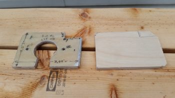
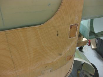
After I marked out the dimensions of CS109 & CS118, I then pulled out a scrap piece of the 1/4″ Finnish Birch plywood that is used for the firewall. Since I had no other scrap plywood pieces big enough for either plywood bulkhead, I had to get into the closet, which was a feat unto itself! ha!
I found some good spots to cut out the new plywood bulkheads, marked them up & then cut them.
[I should state that this was not my first foray into cutting wood today. I actually started by cutting the four (4) WA16 Spruce wedges for mounting the engine mount extrusions to the spar & longerons. One of them needs to be a bit taller, so I will be re-cutting one more. They are in a rough stage now & still need to be sanded. Sorry, the only pic I have of them currently is at the end of this post.]
Here’s a shot of the new CS109 plywood blank.
And the same for CS118.
As a reminder, the reason why I’m redoing the CS109 & CS118 control stick mount bulkheads is due to the fact that the Cozy Girrrls sell the Cozy style stick mounts (I’m guessing….) for the Long-EZ. In the pic below, which I shamelessly stole from my buddy Dave Berenholtz’s site, you can see that the CG stick mounts straddle the CS105 control tube, whereas in the original Long-EZ the control stick merely bolted to the inside the CS105. If this lost 3/4″ offset to the inboard side of CS105 isn’t accounted for, then clearing the side wall either top or bottom of the stick will be problematic. Interestingly, and as I told Dave in an email, since I widened my fuselage and my armrests just a hair bigger, I had already kicked the holes in CS109 & CS118 inboard by 0.4″. I might have actually been able to get away with doing nothing, but it was good that I took these off. The good part is that I only had to move the holes another 0.35″ inboard.
Below is a shot of todays machinations. I also trimmed the GIB handle tube to length (6″, at least for now) & cleaned it up. BTW, it weighed in at a whopping 0.086 lbs, and that’s with the grip in place.
•••
2 October 2016 — I started off today acting upon some information that I got from my buddy Dave Berenholtz down in OZ. He said that his Long-EZ was built in 1987 and that over the years the requisite plan’s holes in the bottom of the Instrument Panel –with the foam exposed to air, etc.– have deteriorated significantly from the edge of the foam not being treated. This jived with what my Instructor from the EAA Composites Workshop stated when he said that builders should always cover exposed foam with either micro or flox.
So today, before I got started on re-installing the CS109 & CS118 control mounts, I decided I would get the lion’s share of this task knocked out. I figured that if I channeled the foam in the lower Instrument Panel holes before I started any glassing, then I would use whatever leftover epoxy I had at each step to use for micro to edge these holes.
After I used the Dremel tool to remove a small channel of foam around each of the Instrument Panel’s lower holes, I then cleaned up the dead glass from the previous install of CS109.
I then did the same thing in the back seat, and cleaned up the existing glass from the previous CS118 install.
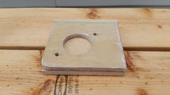
I cut 4 plies of BID on the table (not shown), one for each side of the respective control mounts, and then set about to drill the #12 holes through CS109.
Here’s a shot of the AN3 bolts test fit.
I then did the same thing for the aft-side CS118 and test fitted those AN3 bolts as well.
To ensure I could remove the arm rests after the 5 min glue stuck CS109 & CS118 to the fuselage sidewall, I covered the top inside armrests with clear packing tape.
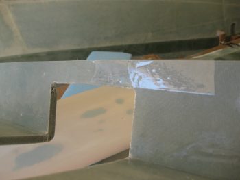
I then 5 min glued CS109 in place to the fuselage sidewall, while taping it in place with duct tape to ensure it aligned properly.
Of course I did the same thing in the back for CS118.
The forward CS109 control mount wasn’t as solidly stuck in place with the 5 min glue, so I went ahead and worked the back CS118 mount first. Below you can see that the 5 min glue did its job and kept CS118 right in place.
I whipped up some MGS285 epoxy with fast hardener, and then some flox, and added flox fillets in the corners.
I then laid up 1 ply of BID on each side of CS118 and peel plied the layups.
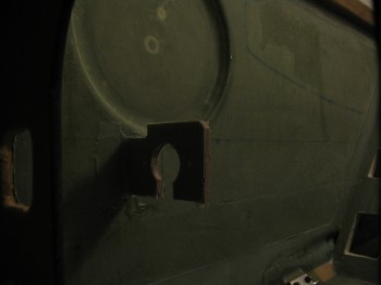
Since I still needed the tape on the front side to secure CS109 in place, I simply laid up 1 ply of BID on each side, but kept each ply small at 2″ x 2″… just enough to lock in the position of the CS109 control mount & keep it aligned properly with the arm rest. I then peel plied the layups [Note the micro in the foam edges of the lower instrument panel holes].
After the layup cured, I pulled the peel ply off the CS118 layups & razor cut the BID glass.
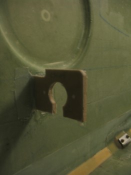
Here’s a shot of the new & improved CS118 glassed into place. Tomorrow I’ll finish sanding the edges & redrilling the bolt holes.
The CS109 mount initial attachment layup came out fine as well. I didn’t realize that I had floxed in such robust fillets, so that sucker will definitely be strong! Tomorrow I’ll add another full ply of BID to the front and aft side.
I quickly double-checked the fit & alignment with the front right arm rest, and it fit great!
•••
3 October 2016 — Today I started out by laying up the 1-ply of BID on the forward side of CS109 that I had intended to yesterday, but needed to go with smaller corner layups in order to have CS109 taped in place to the right arm rest so that it would be positioned correctly.
Normally I would glass the aft side of CS109, but after reviewing the plans, and since I do have a small corner piece of BID on the aft side, I’m going to leave it until I glass the arm rest in place (yes, I am in the current minority of builders that still plans on glassing my armrests into place & not make them removable).
[Note: I cleaned up this layup a bit more after this pic . . . in case you’re wondering (smile)]
I then sanded the cured BID on the aft control mounting bulkhead, CS118, and then redrilled the #12 holes. CS118 is complete.
•••
4 October 2016 — Today I started out by laying up the 1-ply of BID on the forward side of CS109 that I had intended to yesterday, but needed to go with smaller corner layups in order to have CS109 taped in place to the right arm rest so that it would be positioned correctly.
Normally I would glass the aft side of CS109, but after reviewing the plans, and since I do have a small corner piece of BID on the aft side, I’m going to leave it until I glass the arm rest in place (yes, I am in the current minority of builders that still plans on glassing my armrests into place & not make them removable).
[Note: I cleaned up this layup a bit more after this pic . . . in case you’re wondering (smile)]
I then sanded the cured BID on the aft control mounting bulkhead, CS118, and then redrilled the #12 holes. CS118 is complete.
After the layup cured, I pulled the peel ply and knife trimmed the CS109 front side layup.
Again, I’m going to wait to glass the aft side CS109 until I install the right arm rest. Tomorrow I’ll sand this mount down and redrill the #12 holes.
•••
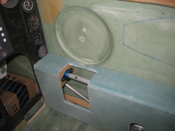
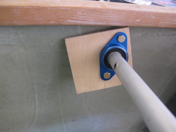
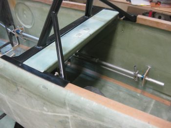
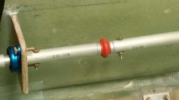
5 October 2016 — Today I mocked up the CS105 control tube & test fitted it in place in the CS109 mount. With the CS105 tube moved inboard, the hole through the front seat will have to be widened just a hair in the area I’m pointing out with scribe in the pic below left.
And did the same on the aft side with the CS105 control tube test fitted in place in CS118.
Here’s a shot of the CS105 control tube test fitted in place in both the CS109 & CS118 control mounts.
I then set the right side pilot arm rest in place, with the CS105 control tube test fitted in place.
I then did the same with the GIB armrest, with the CS105 control tube test fitted in place. Thankfully, the fit on both forward and aft right armrests are fine.
•••
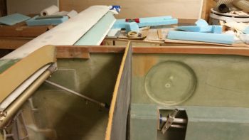
6 October 2016 — Technically, the left side consoles are Chapter 24, but I am posting them here in Chapter 16 as well. Today I unleashed the Big Dog . . . literally, my Big Dog router table from the outside shed. I went through the trouble of pulling this sucker out since there’s simply no way to get the radius I want on the top armrest pieces (and to match the pre-existing radiused edge) without using a router table.
I set up the router table to route a small scrap piece of 3/8″ foam that was probably from the same originally piece as my side consoles since it has a ply of glass on one side. I would have actually preferred to put the glassed side of this scrap piece on the inside of the left armrest and had fresh foam on the outside, but the way the scrap piece wass shaped I had to radius the side with the 1 ply of BID on it.
Here’s the end result. Sooooo EZ with a router table!
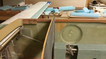
Now, me being not one to waste a good power tool while I have it out, I pulled the front left armrest pieces out and raidused the top piece of that.
Here’s the long, narrow top piece of the front left armrest console.
And here’s after I rounded over the edge.
And a quick mock-up… looks good!
With nothing left to router, I put all my tools back in the shed and got busy glassing my newly rounded extension in place on the GIB left console. I micro’d the piece in place & then used 1 ply of BID. Remember, I’ll add a complete other ply of BID to all of this when I glass in place during its final install.
If you’re curious why I needed to add this piece back in place, it’s because I had originally thought I would put my GIB throttle quadrant right there. Well, first off the position is way too far aft… so my estimated positioning was way off. Secondly, after flying in Marco’s bird and having a few rounds of discussions at RR, I decided to forego installing an aft throttle quadrant to simplify my build and save weight & complexity.
Finally, if you’re wondering why I seem to be making the front of the left arm rest longer… I am. Another benefit of having experienced flying in the back of Marco’s plane is that things that may seem like they’ll work in planning (like my original positioning of the throttle in the back) simply don’t. In Marco’s Long-EZ he has a PTT button on the front face of the left side armrest. I can’t use it because I just can’t reach it. With the tight quarters in the back seat, I can’t bend my hand around to hit the button. So, in my plane I’m going to extend the left side GIB armrest a few inches forward and see if that does the trick since I do think that’s a great place to locate the GIB’s PTT button.
I then pulled the peel ply and knife trimmed the layup on the top extension for the GIB left side armrest. I did note that there was one delam right at the junction of where the new foam was micro’d in, so I’ll have to inject it with some epoxy.
I’m getting the hint that when foam is set in place with micro, it appears that if I put it under the heat lamp it off-gasses and then causes a small dlelam right at the micro’d foam junctions. That’s exactly what happened when I glassed in yet another piece of foam to the side of left side GIB armrest. There’s another delam bubble that I’ll have to contend with…. I guess I’ll get my money’s worth out of the syringe tomorrow.
This is the last extension that I’m planning for the left side GIB armrest. I will shape it and glass the exterior side, and then I should be pretty much done with it until later when I assess whether I’ll mount a front plate or not for a possible PTT button.
•••
7 October 2016 — Again, although technically Chapter 24, I’m posting this here as well. Today I started by checking last night’s layup on the GIB left inside armrest.
I then got to work on the final piece that needs to be glassed on the GIB left armrest extension. I drew up what I wanted as the profile outline.
 Then cut the foam & shaped it a bit.
I then sanded a nice round over on the lower edge and the adjoining glass to transition it nicely in prep for glass.
Here’s a shot of the big layups in action! To the left you can see I have a ply of BID laid up on the front edge of the GIB left console.
Below is the shot of the final glassed extension on the GIB left side armrest. Yes, it looks a tad rough, but once it’s cleaned up and finished it will look stunningly normal!
•••
8 October 2016 — Today I marked the left GIB armrest to cut it at 2.1″ wide on each end (stock is 1.9″).
I then did the cut-fit-sand cycle for about 8-10 times before dialing in the fit of the left GIB armrest.
•••
13 October 2016 — Today I widened the hole in the pilot’s seat where the flight controls transition through. Due to my use of the Cozy Girrrl control sticks, and my subsequent remounting of CS109 & CS118 control mounts –to kick the control tubes 3/4″ inboard– I now have to deal with 2nd order affects in that the control tube transition hole in the front seat is too narrow. To be fair, it was nearly too narrow from day 1, no matter how I configured the controls.
Regardless, it was time to enlarge the hole in the front seat.
As you can see, I marked it off using a very scientific method called “eyeballing it”. I will state that my initial crazy pattern here is not my own, but one I plagiarized from my build buddy Dave B. So if it looks weird, blame him! ha! (Love ya Man!)
I then used my Fein saw and a hack saw blade to make the initial cuts.
I had originally planned on working on my control system at this point, but since I had whipped up so much flocro for the canard filler pieces, I went ahead and dug out a small trough of seat foam along the sides of the freshly cut extended hole areas and filled in the edges with the flocro.
A bit later, with the flocro slightly cured, so I covered the bottom of the pilot seat back control tube hole with packing tape and pressed on with the flight control system test fitting.
I quickly realized yet another 2nd/3rd/whatever order affect from moving the control tube inboard 3/4″, and that was now the hole in the Instrument Panel bulkhead was too narrow for the control tube that goes forward & links to the elevator torque tube. Thus, I marked it for cutting as well.
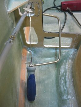
Since this is really tough foam, I drilled small holes along the cut line. I then disassembled my coping saw and put it back together with the blade on the inside of the hole that needed to be opened up.
[I opened up the hole, but apparently forgot to take any pics of it. But you can see the widened hole to a degree in the pics of the control system below.]
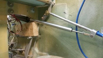
I then mounted pretty much all of the flight control system in the cockpit.
Here’s the aft (GIB) control stick.
And the pilot’s control stick.
A close up of the pilot’s control stick assembly.
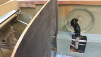
I then set the arm rest consoles in place. Both the front seat . . .
and the back seat. Of course I had to throw on the actual control stick grip as well!
And here’s the grand finale shots of the evening.
•••
15 October 2016 — Today I set my sites on making an adapter for the Infinity Stick Grip. Technically, I’m making an adapter for the adapter since JD makes these adapters for 3/4″ OD tubes. The tubing on the top of the Cozy Girrrls’ control assembly is 5/8″ (plans dimension), so another adapter is required to get the Infinity stick grip mounted onto the control stick assembly.
As with many things on this build, in prep for these steps over the last few days I had to Google some of this stuff. I got the specific information on how this adapter is made from a forum post from Bernie Siu. I can’t find it just now, and I tried going to his website, but it is out there.
I first took the plans identified 5.2″ piece of 3/4″x0.58″ walled 6061T6 aluminum tubing and cut it down so only 0.6″ hung out the bottom of the Infinity Aerospace adapter (standing on end in the pic below)… making the overall length of my new adapter about 2.75″.
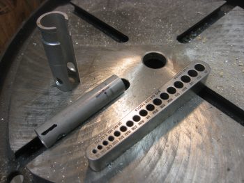
Then, as per JD’s instructions, I drilled a 29/64″ hole all the way through the new adapter to match the 29/64″ hole in the Infinity adapter. I then drilled two more 29/64″ holes perpendicular to the first set of holes & only on one side of the tube. I then essentially connected those holes to make a wide slot down the center of the tube. This slot allows the multi-wired stick grip cable to transition through these adapters. Unfortunately, my Dremel tool died so I had to cut the entire slot sides by hand!
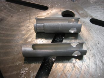
I needed 8 hands to keep the innards of the control stick from flying out everywhere when I mounted the adapters inside the stick, so unfortunately I didn’t get any pics of that insane process. As you may be able to tell below, the stock adapter slides around the adapter that I made this afternoon, which in turn slides onto the control stick assembly.
Below you can see that the control stick grip is just too high. I have to cut that same size channel into the bottom control stick assembly in order to get the cable out of the control stick without pinching it. That should let me get the correct stick height dialed in. In addition, I’l have to sit inside the front seat and test out the control stick in order to “clock it” correctly to know exactly where the front of the stick will face. This will determine precisely where I need to cut the channel in the bottom control stick assembly.
•••
17 October 2016 — I started off today by spending a good 45 minutes mounting the elevators to the canard. The hinge pins went in significantly easier than they have in the past, but I still have to flip the canard right side up to get the pin tips to natural hang point down inside the elevator tubes to get get them through the middle hinge pin bracket.
After getting the elevators mounted, I then gathered up the hardware & attached the elevator push rod end to the outboard side of the right torque tube offset arm.
With the canard & elevators remounted, I then clamped the outboard ends of the elevator to the outboard ends of the canard to set the elevator at 0°. I know that the elevator is positioned just a bit lower than this during cruise flight and I would intuitively think that the control stick position would correlate with the cruise position, but since nothing is referenced in the Roncz canard plans I went with the original Chapter 11 plan’s “neutral elevator” position… although I guess that could be interpreted a few different ways. Nonetheless, I called this 0° neutral and rigged the elevator control push tube accordingly.
[A side note: for some reason my elevators are about 3/16″ off between the two sides at the outboard tip. I’ll use the hot weather trick when the weather gets hot again next year to straighten them out. Not sure why they’re off, perhaps they settled in differently during storage].
With the elevators pinned at 0°, I then set the control stick positioned 5° forward as per plans. I then marked the CS136 control tube, cut it and then drilled & riveted the rod end into place. I then mounted the elevator push tube to make my first officially moving control surface!
Here is the elevator with the control stick at neutral.
And again with the control stick full aft.
And the stick full forward.
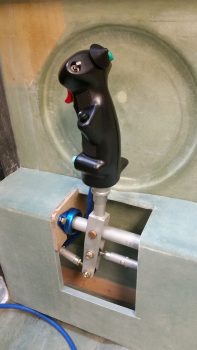
With the elevator rigging completed, I then turned to finalizing the installation of my Infinity stick grip. To make clearance for the decent-sized cable exiting the bottom front of the Infinity stick grip, I needed to mirror the cable channel on the stick grip adapter onto the CS103 control stick tube. I sat in the pilot’s seat and set the stick so it was “clocked” correctly for my hand in a natural position. I then marked the intersection of the Infinity stick grip adapter and CS103. I then removed the stick grip and finished marking the channel that would need to be cut into CS103.
Since I haven’t been able to repair my downed Dremel Tool yet, I bought a cheap HF rotary tool for less than $20 and used that to cut the channel in my CS103 control stick. I left 0.8 of full tubing on the bottom of CS103 for strength and to have an area to drill & mount an AN3 bolt which will secure the Infinity stick grip.
Then, just to make sure I got it right, I climbed back into the seat and did one final clocking of the control stick position. I marked this final position at the base of the stick . . .
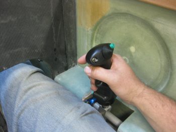
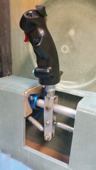
and then drilled the base to accept an AN3 bolt. I then attached the bolt & Voila! My front Infinity control stick grip is officially mounted!
Here’s a better shot.
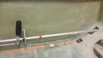
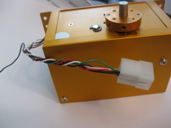
With the elevator controls rigged & my stick grip mounted, I then spent a few minutes getting a feel for how the Atkinson pitch trim assembly was going to get mounted into place. As you can see, I wedged the pitch trim assembly up into place using a 2×4 resting on the rudder pedal. [Also posted in Chap 17]
Here’s a shot from the front of the plane.
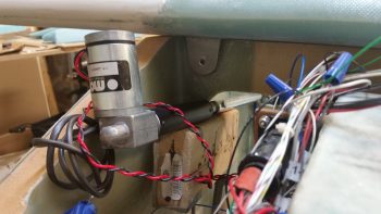
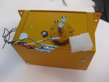
Here’s another shot with the actuator motor turned facing down, which may be required for clearance for the top of the nose. I also need to set my rudder pedals in their final position and check that my right foot has clearance with the pitch trim assembly.
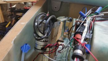
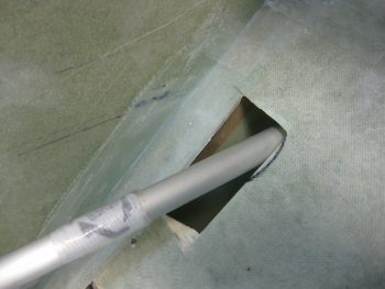
After I removed the canard, I tested moving the pitch trim assembly aft into the area between F22 & the IP. Although my foot could be very close to the actuator assembly (what isn’t a tight fit in a Long-EZ???) this may just be a viable mounting position.
Done with my pitch trim test-fitting shenanigans, I then moved forward with preparations for mounting the Trio autopilot pitch servo. Since I’m messing with the elevator control system, I figured now was a good time to knock out installing the AP pitch servo mounting.
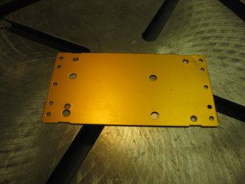
If you remember back a few months ago, I had to send my pitch servo back to Trio to have them install the auto trim option. In transit back to Trio the Postal Service decided to drop kick this sucker… enough so that even buried in inches of bubble wrap they managed to ding a corner of the mounting baseplate. Well, most things work out for a good reason in the end, and this was one of those. Chuck at Trio sent me the dinged mount back with the upgraded pitch servo. I figured it was a novelty item until it came to actually mount the pitch servo. After digging into the installation manual & documentation, I realized this dinged baseplate will serve as a perfect mounting base for my pitch servo install!
Although a bit out of order from the installation instruction sheet I got from Chuck, I cheated a bit using Nick Ugolini’s documented install instructions and went ahead with cutting the pitch servo pushrod to length (4.05″).
I then mounted an HM4 rod end on the freshly cut end (elevator side) using 1/8″ rivets.
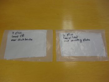
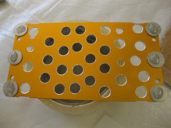
Then, to lighten an already light pitch servo mounting base, I made Swiss cheese of the previously dinged up base. More importantly, these holes are to allow flox to ooze through and better secure the mounting base. A final important note is that you can see that a compelling reason to use the dinged up mounting base is that it already has holes that align perfectly to the actual pitch servo base mount. I called Chuck earlier to confirm that it was ok to drill the out these mounting holes to accept a 10-32 bolt, thus allowing me to use Clickbonds to secure the pitch servo in place. Also, since the AP servos are sensitive to twist & minute movements that can cause slight errors in AP track functions, I’m using 3 Clickbonds per side to ensure the pitch servo is mounted securely and as little twisting action as possible is allowed during operation.
I then sanded the area on the right sidewall in prep for mounting the AP pitch servo.
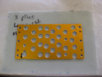
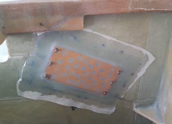
My last task of the evening was cutting 5 plies of BID for mounting the AP pitch servo. All the plies allow for 1″ overlap around the AP base mount, so they measure 5″ x 8″. The layup schedule for these will consist of the Clickbonds getting floxed into place, 3 plies of BID over the Clickbons, the base plate with liberal amounts of flox and then finally 2 plies of BID on top.
•••
18 October 2016 — Today was all about getting the Trio Pro Pilot Autopilot pitch servo mounting bracket glassed in place on the right fuselage side wall. Since I prepped everything last night, it allowed me to just jump into the fray this morning.
I started by cleaning off the Clickbonds with Acetone & then adding a dab of 5-min glue to the bottom of each one. I had them in place in the mounting bracket to allow me to align the Clickbonds to the actual pitch servo bottom mounting plate when I glue them to the sidewall.
I then lined up the whole assembly and pressed the Clickbonds into place onto the fuselage sidewall. I held it there by hand for about 3 minutes to ensure the 5-minute glue set up. I kept the bottom edge of the mounting bracket aligned with my angled alignment mark that I had made on the side wall, and my left-right alignment was my arrow on the lower left corner of the mounting bracket that aligns with the intersection of the slanted alignment mark and a point 7-3/4″ aft of F22.
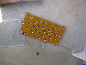
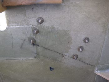
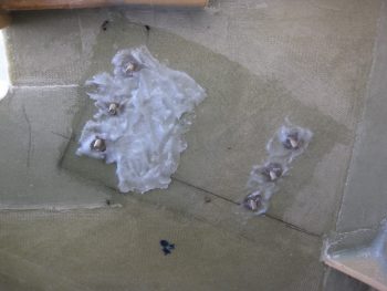
After a few more minutes I pulled off the mounting bracket from the Clickbonds, and after a few double-checks on their alignment, let them cure. The middle dark area just to the right of the left row of Clickbonds is actually a 2-ply BID layup I threw on the side wall to help fill in the elevation gap between the uber 4-ply BID that secures F22, and the sidewall just aft of all that thick BID pad [not a big deal, but perhaps the install could have been better engineered by the Trio gang to avoid this 4-ply BID pad-to-sidewall transition area?….still, no big worries].
As the Clickbonds cured I whipped up some epoxy and wet out the prepregged 3 plies of BID. I then used the mounting bracket to mark the BID to allow me to cut small holes in it for the 6 Clickbond access holes.
I then whipped up some flox and applied it around each Clickbond base and in the transition area to provide a straight foundation for the mounting bracket.
I then laid up the prepregged 3 plies of BID. While the prepreg plastic was still on, I taped up the bottom of the pitch servo for anti-gunk protection and used the actual servo to press in on the flox to attain the exact amount of flox angle required for the servo to sit flat against the sidewall.
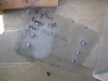
I then pulled the peel ply top plastic, applied a bunch more flox and then set the mounting bracket into place. I then laid up the 2-ply BID prepreg over the mounting bracket. Again, with the prepreg plastic still on, I once more set the actual servo on the Clickbonds and applied firm pressure to set the mounting bracket, flox and BID plies into place.
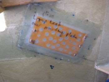
I then pulled the prepreg plastic and peel plied the entire layup.
•••
19 October 2016 — I started today off by peeling the peel ply off the autopilot pitch servo mounting pad & doing some minor cleanup around the edges of the layup.
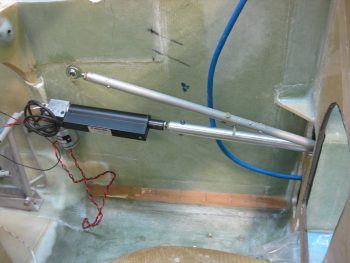
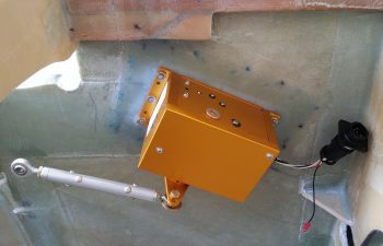
I then mounted the pitch servo with the control rod in place to show what it will pretty much look like when installed operationally.
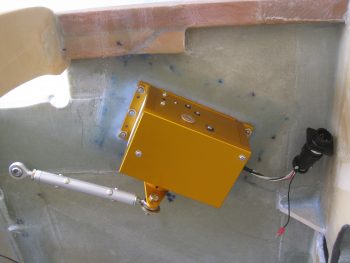
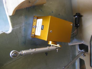
I took the pic below with my phone and included it here because it shows the actual color much better, which is a rich yam orange vs. a sweet potato gold showing up in the pics above.
I had to run out and run some errands for a few hours, but when I returned home I went to work on fixing the “crease” that was running down the middle of my Infinity stick grip. Something was misaligned inside to cause a noticeable edge of one half of the stick off from the other.
The first thing I did was to “crimp” the adapter I bought from JD at Infinity to more closely encircle the adapter I made. The second thing I did was reroute some of the internal wires that I think simply had nowhere to go so was bunching up a hair and knocking the halves just slightly askew.
Still, it was the proverbial “herding cats” game but I finally got it. I then torqued the screws down to keep it that way, only to read a few minutes later in the instructions: “Don’t over tighten the screws!” . . . oh, well. They are tight!
So far the problem is solved, but I’ll have to play around with it for a while to see if it regresses before I add blue Loctite to the threads.
For those of you more esoteric types that like more pastel colors, like turquoise, I offer you this . . . I call it, “Nouveau Grip.”
With my metal cutting tom-foolery behind me, I started working on a quasi-requirement of Trio for the autopilot. In the manual it states to not have the autopilot act as the hard stops for the aircraft control system. Although we don’t have hard control stops in most of our Long-EZs, I decided I would do what I could and put in a stop for full aft stick.
I had originally thought I would put a stop in both sides, under each torque tube offset arm. I may still do that, but for now I decided to just do it under the offset arm where the pressure is getting applied from the control system: the right side. Nonetheless, when I decided this, I had already marked the area on the bottom of the canard where the finish needed to be removed to get to bare glass (below). I did this for both left & right sides.
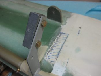
Here’s a couple shots with the finish removed, and with the glass sanded and ready for glassing.
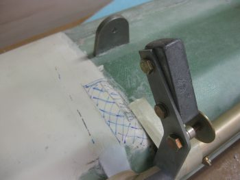
Here’s a long view with the elevator control hard stop in place. The elevators are set at just a skooch over 30° at about 30.5°, just to make sure the full operational limit is obtained.
In addition to Trio’s requirements (which apparently I’m meeting only 25% of! …. actually, I talked to Chuck Busch and he said all was good with my install plan!), I found an old CP (CP# 48 pg 4) that stated some canard pilots were having issues rotating if they pulled full aft stick and the elevators went past 30° down. This gets into the backside of the lift curve and interestingly may not get the nose of the plane off the ground. As per the CP, in this scenario one would be “on the “back side” of the lift curve, lift is less than maximum and the elevator is creating lots of drag.” Marco was having some of these same type of issues on his plane, and found that NOT going full aft stick on takeoff was giving him better liftoff. Of course I’ll test it out and adjust the stop as necessary IAW this CP.
Here’s a closer shot of the elevator control stop.
I then floxed the elevator control stop in place, made some flox fillets and glassed each side with 1 ply of BID initially. Then, since I had enough epoxy, I added one more ply of BID to the inboard side since my first NON-prepregged piece of BID decided to go just a tiny bit wonky on me. I then peel plied the glass intersection on the canard surface.
Later in the evening, I reinstalled the Infinity stick grip in the arm rest and tested it out. Alles ist gut! . . . so far.
•••
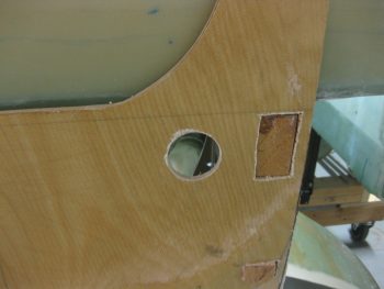
20 October 2016 — Today I really started back on the control system by marking where the aileron control system bearing (CS123) gets mounted into the firewall. The plans state W.L. 12.3 and B.L. 6.2R, so that’s what I marked up.
I then grabbed my German hole saw and drilled a 1.5″ hole (stock bearing is 1″, but the much nicer Cozy Girrrls bearing is 1.5″ in diameter).
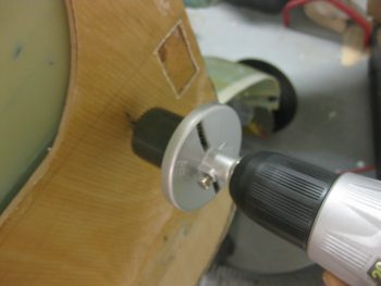
When I drilled the hole, I angled down and to the right just a bit towards the U-joint on the end of the CS116 control tube.
Since the hole I drilled was almost exactly 1.5″ in diameter, I had to sand the hole with the round Perm-a-grit tool. Just a few minutes worth of sanding did the trick, and then the bearing fit perfectly.
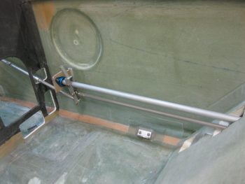
Here’s a closer view . . . both pics obviously have the CS122 control arm inserted.
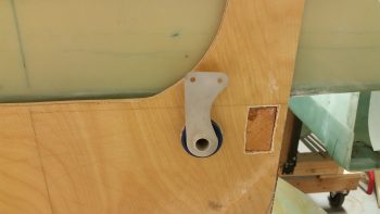
Here’s a view bore sighting down the CS122 control tube… the object at the other end is a little out of focus eh?
Well, let me help! It’s the U-joint at the end of the CS116 control tube!
Here’s a shot of the aft cockpit flight control setup
Of course there’s NO plug & play on these birds, some trimming is ALWAYS required!
OK, maybe a lot of trimming. This is what happens when it’s required to modify the aircraft for non-standard parts (in my defense, I had no idea that this control system would need so much re-wickering of stuff. I may have just not bought the CG’s control kit and rolled my own if I did!).
Even the arm rest’s front interface with CS118 is jacked up now! Clearly I’m going to have to do a little bit of tap-dancing to get all this stuff to work right . . , like it did before I went that ONE next step! ha!
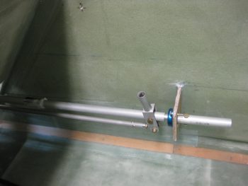
To feel like I was actually getting something accomplished, I went ahead as per plans and drilled a #12 hole through CS121 and the control U-joint (also as per plans I started with a 1/8″ pilot hole).
I then bolted in an AN3-11A bolt –which seems a hair long to me– and mocked up my new CS121 control tube assembly with the existing CS116 control tube.
Here’s another view.
•••
21 October 2016 — [This is posted here as an FYI since it relates to flight controls] My first task of the day was to prep the connection wiring and replace the connector on the Trio Pro Pilot roll trim servo somewhat like I had done with the pitch servo. The main difference here though is that the roll servo will reside in the engine compartment, not the cockpit, and thus will be subjected to higher temps and more of the elements. I wanted to completely protect this wiring and replace the Molex connector with an AMP CPC connector.
I started by removing the Molex connector.
And then removed the 4 individual Molex connector pins.
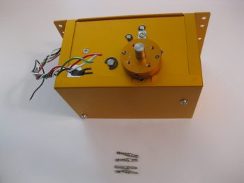
I added a couple of pieces of heat shrink, a flexible wire stay, and crimped 4 new AMP pins onto each of the wires. Technically, in the same way that as the pitch servo, there are 2 ground wires that share the ground pin connector: one to the internal electronics, and one for the case ground.
As you can see, I also crimped a ring terminal in place for the case ground wire. In addition, I snapped each AMP pin into the AMP CPC connector housing and closed it all up.
And a closer shot of the final AMP CPC connector configuration for the Trio Pro Pilot roll servo.
•••
10 May 2017 — As I was working on trying to find alternate solutions and locations for the pitch trim actuator unit, I realized that to do this right I really need to be able to test out any potential obstruction or tight fit that a component may pose north of the Instrument Panel. There’s just one issue with this however: when I sit in the pilot’s seat that itself constitutes an estimated best guess as well, since I have no mounted thigh supports, and no actual seat cushions, etc. In other words, I’m set to make foundational decisions on what goes where in the nose based on a very loose estimate of my seating position, which in some instances is very critical to figuring out what goes where without having my knee constantly banging into something during a flight.
This drove me into yet another mini-epiphany. I need to institute a slight change of direction, with a compass heading just a few degrees off of current. In other words, before I can really press on with getting the nose components in place and dialed in properly, I need to get the pilot seat area squared away. Thus, I need to work from just a bit more aft forward to get this all right.
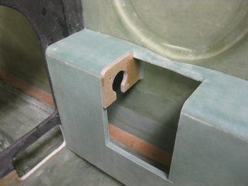
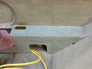
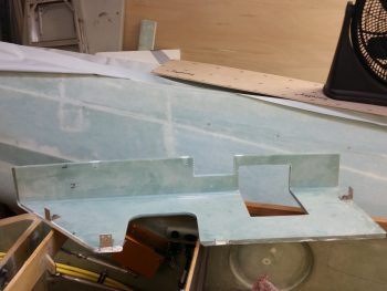
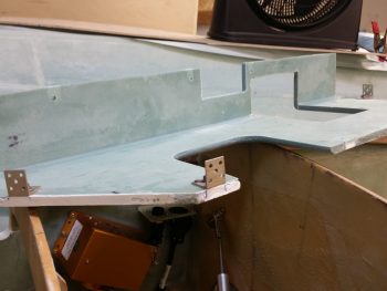
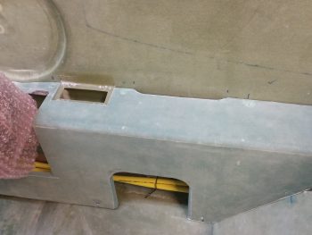
So, the first thing I did was to figure and mark up the notch in the right arm rest for the Dynon Intercom unit.
I then cut out the notch in the right arm rest for the Dynon Intercom unit.
Here’s another shot of it.
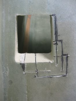
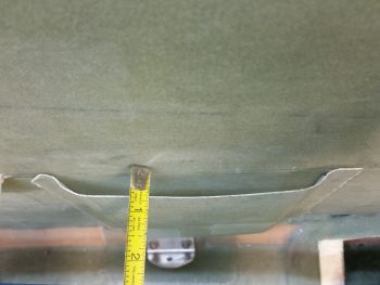
Since I was in the cutting mode on the right arm rest, I decided to finally finish what I started about 5 years ago and widen the seat belt access opening to the plan’s specs. The reason why it looked the way it did above is actually a little comical: I simply read Burt’s forward dimension as 19.5″ vs the actual 14.5″ . . . resulting in a much narrower seat belt access slot.
•••
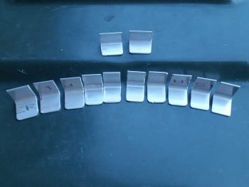
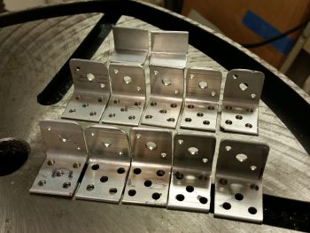
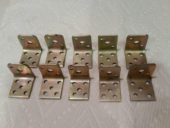
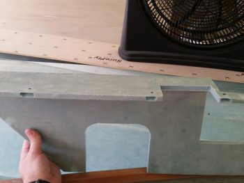
18 May 2017 — Since I had my big miter saw out today, I cut a bunch of mounting tabs out of 1/16″ 2024 aluminum angle for the right front armrest (a lightweight option idea that I stole from Dave B. after he did all the weight comparisons… thanks Dave!). The tabs are shown further below.
I also pulled out my router table to round over the edges of the lap seatbelt access port. I had planned on doing this, just as I rounded the bottom edges of both back seat armrests, but again Dave reminded me of it last week so I put it on the short task list. Now, the right armrest seatbelt access was good to go since I widened & squared it a bit last week. But the left armrest, which is still in individual pieces, I hadn’t touched since 2012 when I cut it out. [NOTE: The left armrest is actually covered in Chapter 24, so this will be posted there as well].
I verified & marked the spot of the left seatbelt bracket on the left armrest. Then I used the right armrest as a template to draw out the seatbelt access port.
I was now ready to cut this baby out!
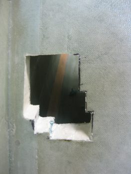
Well, I tried to use a hole saw as I had with the right side. The same exact one in fact. But as soon as the saw blade touched the fiberglass on the back it came off its mount and went absolutely ballistic. It’s done this a few distinct times before, but usually just a minor ding before. No worries. I can assure that this will never happen again with this hole saw because it is no longer with us ( . . . a moment of silent please for the POS hole saw bit).
So, I backed up the aft line about a half inch, upped the top line by about a quarter inch, and cut this sucker out! Here’s the result below.
I then radiused both left & right armrests using my router table. As you can see, now just a little bit of extra micro will fill in that gouged foam EZ’ily.
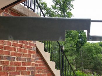
I then cleaned up the right armrest mounting tabs and rounded the corners of the edges that would be protruding out of the wall. I have to say I’m not a big fan of leaving sharp edges about the airplane so I feel like I’m entering the Gauntlet every time I have to do work or maintenance in the bowels of the plane!
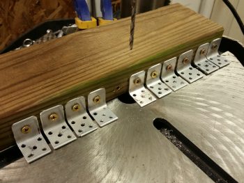
I know there’s a myriad of ways to do this, but I wanted to Alodine these along with the fuel drain valve hardpoint blocks, so I drilled all the necessary holes to flox these to the fuselage sidewall, and mount the nutplates. I started by drilling out the main hole for the screw to go through the tab top into the nutplate. I then used that hole with sheetrock screws to mount the tabs to the side of a scrap 2×4. I then drilled the 5 flox anchor holes into the fuselage mounting side of the tabs.
I’ll note that I specifically wanted these tabs a bit narrow, which meant mounting each nutplate at an angle for it to fit. This angle caused the nutplate center to be pushed out just a hair further from the sidewall by 0.55″ (center of mounting screw). This is a bit more inboard (off the wall) than I would have wanted, but because of the inside filleted corner on this angled 2024, the screw hole is at most 0.1″ farther out than if I had mounted the nutplate parallel to the corner junction, and/or perpendicular to the side edges.
A final point I’d like to make on this is that my more inboard hole placement also has a benefit in that since I’m not glassing the armrest in (as a structural piece), I am not concerned about it’s strength as a structural aircraft member as per the original plans. Thus, now it becomes simply an armrest, so I will not be adding the second ply of BID to it as I had planned to do when I would install it via glassing it in place (again, 2-plies as per plans). With only 1 ply of BID on top, the more inboard the screw (away from the wall), the screw has just a bit more meat to bite into for strength (not huge, but every bit helps).
After that, I used a K1000-3 nutplate as a template to drill out all the rivet holes.
I then counter sunk the rivet holes on the top side to allow for a nice flush fit with the inside surface of the right armrest.
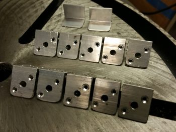
I then Alodined all the aluminum parts I created today, except for two. You’ll not the 2 pieces up at the top in the above pic that aren’t drilled out and that I left blank. Those are spares 6061 pieces that are narrower in depth, and that I may employ at the very front of the armrest where it intersects the panel.
•••
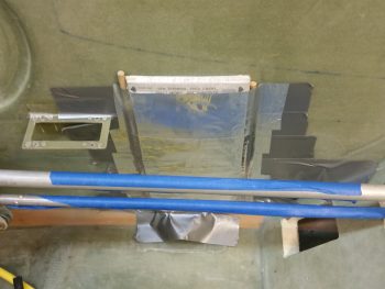
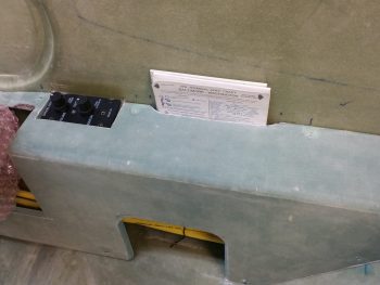
19 May 2017 — After returning home from my social outing this evening, I decided to knock out a fairly quick layup. I want a thin map-style pocket on the side of both armrests right against the sidewall to hold checklists, documents, and yes, even maps, if need be. To verify what kind of documents would fit in this area of the side wall, I pulled out an 8-1/2″ x 11″ piece of standard paper, a small binder, maps, a checklist, etc. I then checked each one to see what would feasibly fit in this area. After some messing about and pondering each one, I kept coming back to the map size, which of course would easily hold a standard sheet of paper folded in half. Or a checklist for that matter.
I didn’t want the pocket to be too thick, and was shooting for around 0.370″ deep from side wall out. I took 3 maps and pressed them together: too thin. I added a 4th map and it was too thick. So, I took one of my old maps and cut it in half and that made the pile very close to 0.370″ thick. To ensure the maps didn’t get messed up, I wrapped them in shipping style plastic wrap, then taped them with clear packing tape.
I was about ready to lay this up on a work board when I realized that the work board is totally flat, but most likely my fuselage sidewall is not. So, I checked the sidewall and sure enough, it wasn’t totally flat & straight. Thus, I decided to simply slap this map-packet up on the wall and glass it there. At first I had some issues with the vertical edges after I duct taped it up on the sidewall. I added the 1/4″ round dowels to help formulate the edge shapes better. I then covered the hole thing with aluminum foil tape, which helped smooth out a lot of the issues I was having with my duct tape base tape. I then quickly applied 1 coat of wax to the aluminum foil tape before starting in on cutting out the glass for the layup.
Since I have a ton of spare UNI laying around, I decided to put some of it to good use. I determined that I needed plies 8.5″ wide x 9.5″ high to cover all the areas with a little extra overhang. When done, the overhang will get trimmed down, but will provide a mounting edge that will allow me to mount this using RTV (or flox if desired).
The resulting layup schedule I decided on was 2 plies of UNI, biased in opposite 30° directions, and 1 ply of BID. Now, since the more robust glass should be where the docs are in contact, I put the BID on the interior side, with the 2 plies of UNI on the exterior side. I then prepregged (big surprise) the whole thing, added a strip of 2″ peel ply along each vertical edge of BID, and then laid this sucker up.
To be clear, with the tape already acting as a barrier, obviously I’m just looking for a good general shape here before I pulled the cured glass of the wall/tape, trim it to good dimensions, then slap it back up using either RTV or flox.
•••
20 May 2017 — I started off today pulling the “map” & document case off the wall. Thankfully, it came off without too much of a fight. I quickly pried away the entombed maps, freed them and threw away the ton of tape from this endeavor.
I then inspected it to see how it came out. It looks pretty good, with some obvious cleaning up required, especially on the inside.
I then pulled the peel ply and trimmed up the “map” & document case and using a couple of pieces of duct tape did a quick mockup on the fuselage sidewall.
I also checked its depth. In the pic below it’s sitting at about 0.45″ from side wall to “map” case wall. But remember, there’s tape under the tabs, and I’ll be able to control at least the top depth by the cutout in the right armrest. The end result is that it should be around 0.4″± ~0.2″.
With the “map” & document case looking ok, I moved on to the right arm rest. With the “map” case on the side wall I was able to determine where my top armrest screw attach points would be located. I then determined the rest of the attach points for the right arm rest, except the very top front and very bottom front areas. These will need special attention based on what kind of stuff traverses these spots.
With my armrest screw attach points known, I used a mounting tab to mark up where the screw hole would be (a very close approximation did fine here). I then dug the foam out so that when I filled in the resulting divot with 30/70 flocro, I would have a nice hardpoint for each screw to mount into.
Finished with my armrest screw hard points, I vacuumed them out & filled them with flocro using fast hardener (results shown later below).
Later, I checked out the flocro in the right armrest. Here’s a couple of shots (albeit crappy!).
I then drilled holes into the armrest and riveted up 5 tabs with nutplates. To limit my variables when installing the armrest, tonight I only floxed in 4 of these 5 mounting tabs (the one at the far right –which is the front side mounting tab– didn’t get floxed tonight).
Not only did I flox 4 of the mounting tabs in place, obviously attached to the right armrest, but I also filled the gap between the armrest and pilot seat bulkhead with micro. This was planned and I had already placed a long piece of clear plastic tape on the seat in position.
Just a slightly closer shot.
Here’s a shot of two of the armrest mounting tab screws.
And here’s the same one on the left, and another one just to the right of the intercom bracket.
At about 1.5 hours into mounting the right armrest with flox I started prepping 4 x 1-ply BID prepreg setups. I was checking the flox in the cup and after almost 2 hours had passed I unscrewed the armrest and pulled it free. With all that micro on the aft side that in itself was a bit of a chore.
Then I whipped up some flocro since I wanted some strength but not a lot of added weight. With the flox still just slightly tacky (green state) I cut off the flox fingers and covered the tabs with flocro, then laid up a ply of BID over each tab. I was planning on peel plying these layups, but it’s really late and I’d rather just hit the edges with some sandpaper later on.
I probably won’t layup any glass on the other right armrest mounting tabs and will let the flox just stand for itself. I did want to get about half of these with a ply of glass on them just for securing the armrest’s sake.
•••
21 May 2017 — Tonight I started by drilling out the screw mounting holes for the aft 2 brackets on the right armrest. I then riveted K1000-3 nutplates to the respective brackets. As you can see, I had already done this for the front bracket last night, but I just didn’t flox it in place yet.
Here’s another shot with the brackets bolted in place and ready to be mounted with flox onto the fuselage.
Again, here are the previous 4 right armrest mounting brackets that I did last night: nicely cured with their 1 ply of BID holding them in place.
I then floxed up the mating side of the 3 remaining right armrest mounting brackets and remounted the armrest in place.
I bolted the armrest in place using the 4 mounting brackets that I had previously installed last night. Here’s a shot of the new forward (against the instrument panel) right armrest mounting bracket . . . well, the bolt head at least.
And a shot of the 2 new lower aft right armrest mounting brackets (right in front of and on the seat bulkhead) bolt heads as well.
•••
22 May 2017 — Today I double-checked the newly floxed-in mounting brackets for the right front armrest. They all looked good.
•••
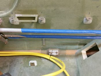
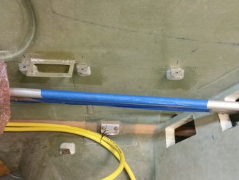
24 May 2017 — Today I needed to figure out my spacing and configuration under the right front armrest for my fuel lines and big power cables, as well as the other smaller wire bundle as well. To do that, well, guess what? I needed to mount the map pocket in its position.
So I worked for about a half hour shaping and dialing in the exact spot it would get mounted. I then transferred the opening shape over to the right armrest, and trimmed a notch in it the size & shape of the map pocket.
Here’s a test fit and a shot at how the map pocket looks with the intercom installed.
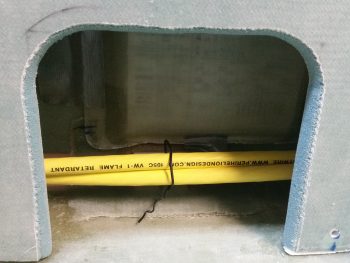
And a pic of the lower map pocket and the big power wires heading for the firewall.
•••
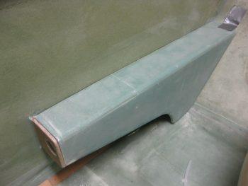
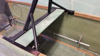
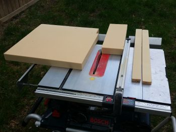
26 May 2017 — Today I pulled my table saw out and cut up some 2″ thick urethane foam for some plugs. The 2 longer strips on the right will be plugs for the heat & air ducts, while the block in the center is the GIB right armrest storage pocket plug. FYI – this storage pocket is somewhat like the “map” pocket in the front right pilot’s console, only much bigger.
I hate wasting dead space in this plane, especially since storage space is a premium in Long-EZs. Since I have just a hair wider back seat bulkhead (around 0.8″), combined with the Cozy Girrrl’s Cozy style control sticks [which straddle the control tube vs. attaching just on the inboard side], I needed to move my control tube assembling inboard about 3/4″ if I wanted the configuration to match that of the plans. All these minor mods served to create a significant gap between the aft control tube and the right fuselage sidewall. A gap that I of course exploited to use as storage.
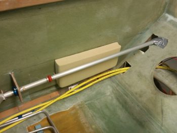
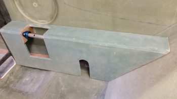
I had jotted down some initial configurations last night, and further dialed those in today to come up with a storage pocket measuring 12.5″ long x 1.7″ wide x 6″ deep (tapering up to 5.2″ deep on the aft side).
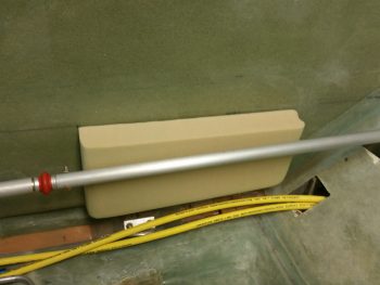
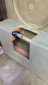
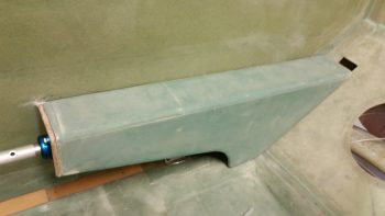
This configuration not only provides a fair amount more storage, but it also allows all the engine fuel feed line, main tank sump feed line, big power cables and a smaller electrical bundle to all traverse around or under it.
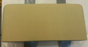
Thus, with my design good, and wanting to dial in the engine fuel feed line, specifically, I decided to go ahead and glass this baby up.
I started by taping up the urethane foam plug with silver duct tape. For a smoother interior pocket surface after it has cured, I then followed that up with a layer of clear packing tape.
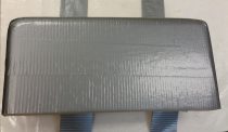
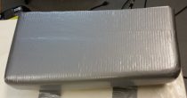
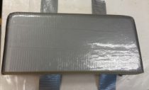
I used BID as the first ply down, followed up by 2 plies of UNI biased in opposite ~30° directions. To add a little bit more stiffness than my “map” pocket, I added 1 more ply of BID that covers the entire side and about half of the bottom and each end.
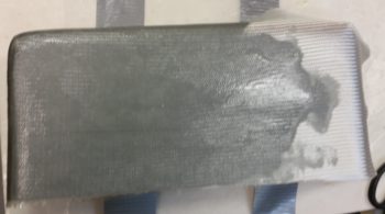
Here’s the glassed GIB right armrest storage pocket.
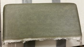
I then peel plied the bottom, front and back sides to allow for future glassing in place with BID tapes.
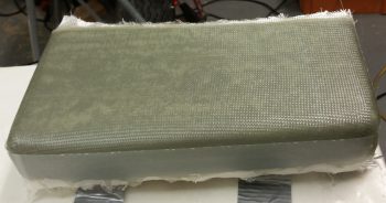
I then left it to cure as I went out for the evening.
•••
27 May 2017 — I started out today by trimming up the GIB right armrest storage pocket and removing it from the foam plug. The pics below show both the front and inside of the storage pocket.
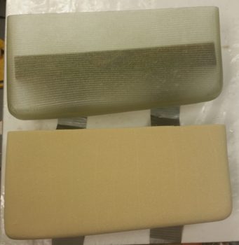
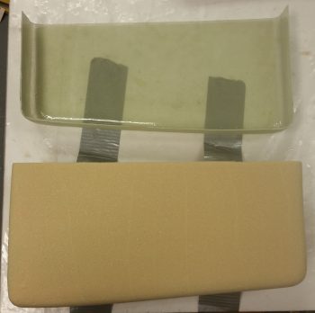
Here it is again, solo.
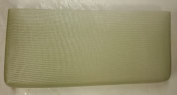
I then mocked it up in place to see how it fit. I can say I’m happy with it, so it will soon be getting glassed into place so I know exactly how to route all my stuff around it!
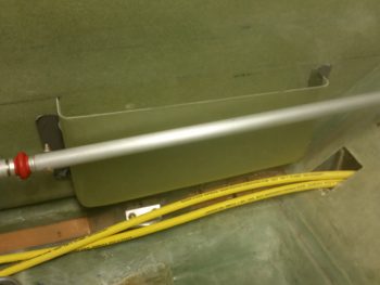
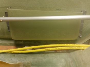
I had to lower it about 0.20″ for the iPad to fit, while in its case. But mounting it just a tad lower also helps me with some lid ideas that I have.
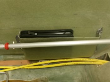
I also had an issue today with the right side armrest that needed some cutting to solve. I simply couldn’t get the armrest mounted since the fuel lines were in the way. I wanted to be able to mount the armrest since I was going to install the “map” pocket permanently to get a final idea of fuel line routing… and just to get it done!
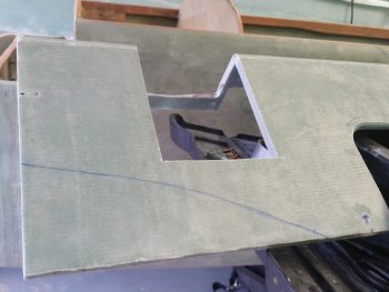
I taped in my 12″ flexible decimal ruler to get a good estimate of what the pilot thigh support ribs profile will be, and then cut it out. Of course, I also wanted to get this area cut out in my continuing effort to get the pilot area sorted out as well to allow me to move on to the nose build.
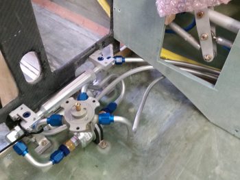
Thus, I also floxed in the map pocket into the pilot’s right armrest during the same round of glassing that I did the for the big power cables’ “final” Clickbond glassing.
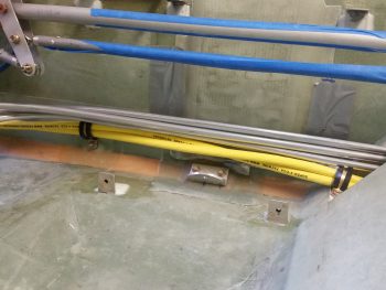
A few hours late, here’s the floxed in place and 90% cured pilot right armrest “map” pocket. I ended up mounting it about 0.050″ lower than I had marked, which actually works out perfectly because there is literally no sign of the actual “map” pocket visible when the armrest is installed.
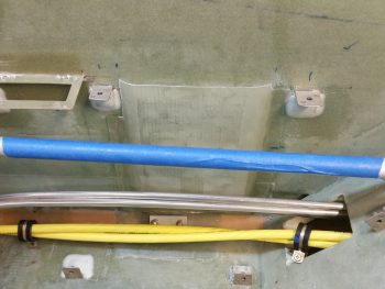
•••
28 May 2017 — Besides the heat lamps, below you can see that I glassed in the aft side of the GIB armrest storage pocket with 2 plies of BID.
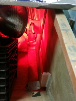
Here it is a bit later after it cured.
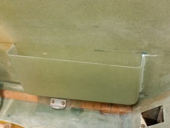
•••
30 May 2017 — First thing this morning, with the same MGS epoxy that I used to glass the outside of the right fuel sump tank wall, I filled in 3 divots with flocro that I had made previously in the exact spots I had chosen to be the screw hardpoints on the armrest.
Realizing that with a lengthy storage pocket the possibility for vibration between the top edge of the pocket and the inside edge of the now cut armrest was very likely, I decided to mount a screw hardpoint at the center point of the pocket. I determined where the hole should be, and mounted a small RivNut there with flox. Thus the clamp you see in the pic, holding the storage pocket firmly against the armrest to obtain the correct spacing on the hardpoint.
[OH, YEAH, I CUT OUT THE NOTCH FOR THE STORAGE POCKET . . . AND BURNED UP MY TRUSTY “FEIN” SAW IN THE PROCESS . . . BUT IT PUSHED ON UNTIL THE VERY END! LITERALLY SMOKING AS I PUT IT OUT IN THE DRIVEWAY AND OPENED UP THE GARAGE DOOR TO CLEAR OUT THE STENCH OF ITS GRUESOME DEATH! WELL, BACK TO HARBOR FREIGHT TO PLUNK DOWN ANOTHER $14.99! HOPEFULLY THIS NEXT ONE LASTS 6 YEARS OF PUNISHING WORK LIKE THIS ONE DID . . . A MOMENT OF SILENCE PLEASE].
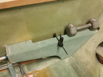
Since I only had 3 drilled brackets from my right front armrest installation frenzy, I decided they would do fine for now. I do intend to install at least 2, if not 3 more mounting brackets. One off the front CS118 control stick bulkhead and one off the middle of the aft angled part of the armrest, about mid-point onto the GIB seatback.
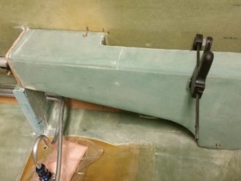
On the left you can just the midpoint screw in place, and on the right I snapped this pic as I was removing it to show a clear shot of where the midpoint screw will be installed.
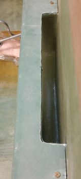
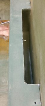
And here’s the midpoint RivNut hardpoint secured in place on the right GIB armrest with flox.
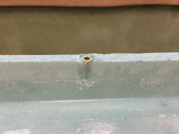
Here’s a shot of all the new right GIB armrest brackets in place, secured with flox. Again, I want to give a shout out to Dave Berenholtz for doing the 1/16″ thick aluminum angle mounting brackets. I honestly would have never thought seriously about using aluminum . . . brilliant Mate!
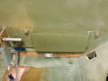
•••
11 June 2017 — Finally, I spent a good couple of hours working on my last batch (hopefully!) of mounting tabs for the GIB left armrest, as well as backfilling some inventory that I stole from the front & aft right side armrests.
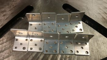
•••
13 June 2017 — Today I finished drilling & countersinking the rivet holes for the nutplates that will eventually get mounted onto the armrest (etc.) mounting brackets.
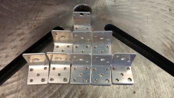
Here’s a shot of the drilled and countersunk rivet holes in the mounting brackets.
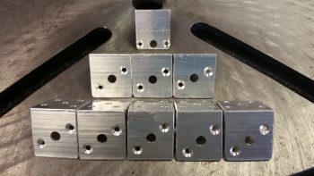
I then Alodined the armrest mounting brackets and the FT-60 Red Cube fuel flow sensor mounting bracket.
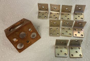
Tonight I floxed in 3 mounting tabs that were screwed to the GIB left armrest. These are 3 of 4 tabs that are located primarily on the aft side of the armrest. I’m planning on building a small framed mounting bracket that will be used to also house the GIB headset jacks and PTT button on the front side of the left armrest, which will have a nutplate attached to it and be the 4th mounting tab.
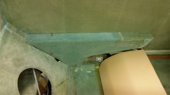
In addition to the left side armrest, I also added another mounting bracket to the GIB right armrest by floxing in place a tab on the aft side of the armrest where it meets up with the seat back.
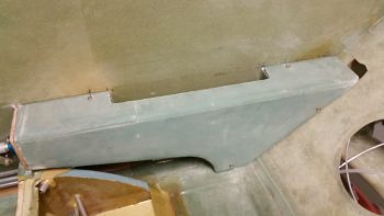
•••
20 June 2017 — Today I marked & dug out the foam on the front edge of the GIB right armrest to create a mounting tab hardpoint. I made up a good mix of flocro and then filled in the hardpoint divot on the GIB right armrest. Later, I’ll flox the GIB right armrest mounting tab into place onto the aft side of CS118 mini bulkhead.
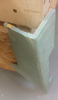
•••
24 June 2017 — Today I configured the front mounting tab for the GIB right armrest. I determined where it would go, drilled the armrest through the flox hardpoint I made the other day and then riveted a K1000-3 nutplate to the mounting bracket. I taped up the edge of the armrest before attaching the mounting bracket to the armrest. I also taped up the top edge of the right GIB storage pocket as well.
I then whipped up some flox using fast MGS hardener and bolted the armrest in place so that the front mounting bracket would be positioned properly as it cured.
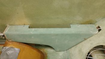
I then whipped up some micro and micro’d the edge of the storage pocket. The goal here is to fill in the gaps between the storage pocket top perimeter edge and the inside edge of the armrest. When I remove the armrest, the micro will have adhered itself to the armrest, especially since the storage pocket edge has tape on it.
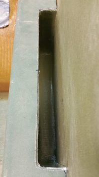
•••
25 June 2017 — I started off today by pulling off the right GIB armrest to reveal a nicely floxed in place forward mounting tab. It is however, a bit too close for comfort to the control tube bearing’s bottom mounting bolt, so some judicious grinding away of some flox and maybe just a hair of the bracket on the outboard side will be in order.
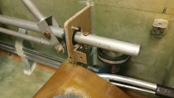
•••
28 June 2017 — Today I spent a couple of hours on the left GIB armrest. First off I DA sanded down the somewhat grotesque layup edges that where created when I added the top and front extension pieces you can see in the pic below. Unfortunately, being in a rush to make up for some lost time on personal stuff today, I had one fuzzy pic and simply didn’t take any others. I know: for shame! The end result is not only did I radius the front edge and glass it with a ply of BID, but I also filled in some holes with micro in a few different areas on the armrest.
Moreover, I cut a square notch on the very top inboard INSIDE corner that will mate up to the GIB PTT button housing that will be incorporated into the sidewall bracket that will also house the GIB headset jacks. In addition to the top curve, I also glassed the inside surface of the PTT button bracket notch I made with 1 ply of BID. Of course all the layups got peel plied. I’ll get a pic of all the interior layups tomorrow.
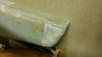
•••
30 June 2017 — I started out today working on the GIB PTT button configuration & construction of a front plate for both the GIB PTT button and GIB headset jacks, all which will reside on the front of the left GIB armrest. It may be a bit hard to tell, but the greenish blob coming down from the top of the pic below is the front of the left GIB armrest. Top of armrest is to the left, with the PTT button resting in the notch I created for PTT button clearance.
I positioned the PTT button notch where it is to get the PTT button as far up into the inboard corner of the armrest front face for easier “mashing” of the button any time the GIB is going to use it. However, to stay clear of the PTT button being inadvertently pressed or an open mike situation, I’m recessing the button so the top of it is just below the face of the armrest front face. Thus, at the center bottom of the pic is the piece of 1/16″ G10 I cut as the armrest front face cover plate, and in the corner where the PTT button will go, I notched it and shaped a piece of Divinycell foam with a 1/2″ diameter hole for the PTT button to sit in. I 5-min glued the foam piece in place, then when cured I radiused the perimeter edge of the hole.
All this is sitting on a piece of 1/4″ phenolic which I drilled a 0.609″ (39/64″) hole into for the actual securing of the PTT button as it’s press fitted into this hole with some Silicone RTV to lock in nice & tight.
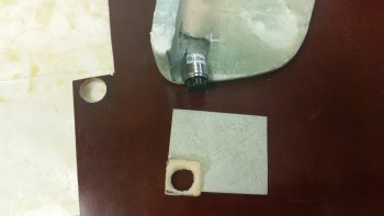
Since the left armrest front tapers aft at the bottom, I tapered the foam PTT button recess housing so that the PTT button would sit parallel with the top of the armrest for clearance on the internal side of the armrest. Here you can see the PTT button set in place where it will get mounted. If you look just forward (left) of the ID label sticker you can see the wider 0.609″ flange that will get press fit mounted into the phenolic. The phenolic piece will of course get floxed to the aft side of the tapered foam recess housing.
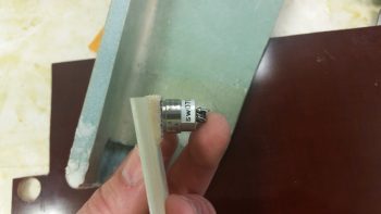
I then tested the fit of the assembled armrest front face piece in the notched corner I created in the armrest. When finished, this front face piece will be an integral part of the sidewall bracket that remains on the fuselage sidewall when the armrest is removed.
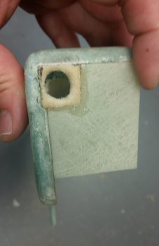
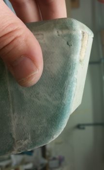
I had to do some very light sanding after I drilled the 0.609″ (39/64″) hole for the PTT button to fit, which it did with a reasonable amount of force. Perfect.
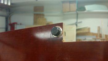
Again, the physical mounting of the GIB PTT button will be in this 1/4″ phenolic block piece that itself will get floxed to the aft side of the foam recess housing that is attached to the front face piece.
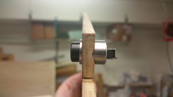
I then cut out the phenolic block and trimmed it up. I then mocked up the PTT button secured in the phenolic block, set in place where it will attach to the foam button recess housing, all with the front armrest face piece set in place.
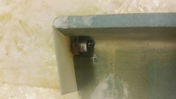
Another shot of the recessed PTT button in the left GIB armrest front face piece.
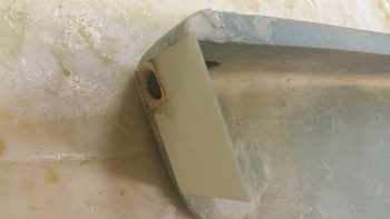
•••
3 July 2017 — Late Friday I laid up 1 ply of BID across the front face plate of the GIB left armrest. I pulled the BID down through the hole in the foam recessed housing for the PTT button.
Well, when I trimmed the glass off on Saturday, unfortunately a good chunk of the foam came with it. I then needed to repair it of course. Being in a rush for a social engagement, I quickly wrapped up the PTT button in saran wrap & tape, and then set it in what remained of the hole and weighed it down. I then whipped up some flocro and –using the taped-up PTT button as a form– rebuilt the recessed housing “frame” around the PTT button.
Here’s a shot of the left GIB armrest’s front face plate, with the repaired PTT button foam recessed housing.
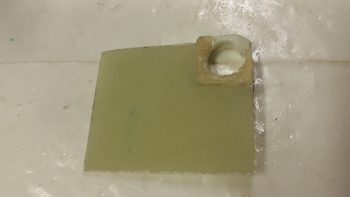
I haven’t sanded down the repaired PTT button foam recessed housing to its final shape yet, but will get to it after the July 4th holiday festivities are over. Still, here’s the aft side of the left GIB armrest’s face plate.
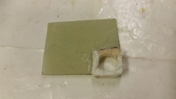
•••
5 July 2017 — Today I got to work on the left GIB armrest forward composite mounting bracket that will also house the GIB PTT button & GIB headset jacks on the front face of it (which will get attached to this bracket frame later). I used a 2″ thick urethane foam block for the form and cut the block 3″ long.
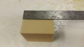
I then sanded the foam block form into shape, radiused the corner edges for glass and taped it up with duct tape.
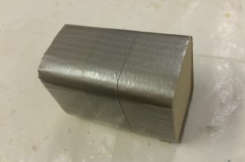
I then cut out 3 strips of 3″ x 8″ BID and 2 strips of UNI the same dimensions for a total of 5 plies of glass. I then put the glass into plastic for a prepreg setup. I also mounted the left GIB armrest forward mounting bracket form onto a vertical stand to make laying up the glass onto it much easier.
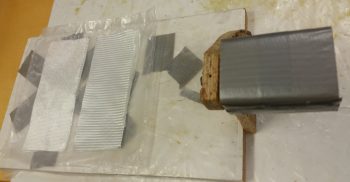
Here’s another shot of the left GIB armrest forward mounting bracket form attached to its vertical stand.
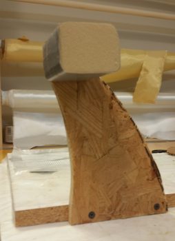
I then laid up the 2 sets of prepregged glass so that the layup schedule was a simple BID-UNI-BID-UNI-BID pattern with the UNI plies at a 30° bias, with each UNI ply in the opposite direction. I then of course peel plied the layup.
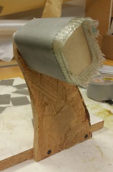
Yet another shot of the 5-ply glass layup for the left GIB armrest forward mounting bracket.
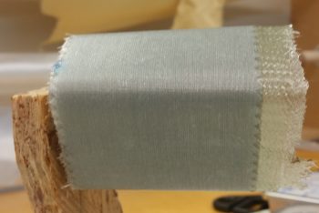
With the same epoxy I also whipped up some micro to pour into a hardpoint divot that I had created at the left GIB armrest forward mounting point.
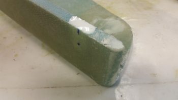
•••
6 July 2017 — Today I started out by removing the foam form out from the middle of the left GIB armrest forward bracket assembly that I glassed last night.
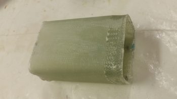
The bracket came out nicely with no glaring errors!
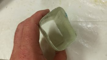
I had glassed it up a bit oversized, so I took a few minutes to measure out my bracket dimensions, mark up the bracket and then trimmed it with the Fein saw.
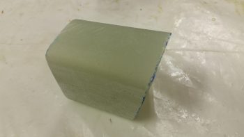
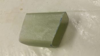
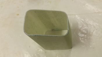
I then got to work notching the bracket in the upper inboard corner for PTT button housing clearance. I also drilled some lightening holes: one on the inboard side and one on the bottom.
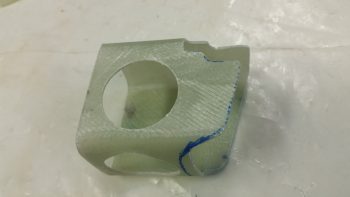
Here’s a good look at the corner PTT button housing clearance notch.
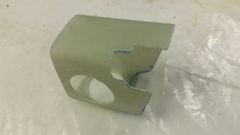
I also notched the front bottom lower edge since the face plate doesn’t come all the way down. By moving the lower edge back a bit, there’s no way to see that the bottom bracket lip doesn’t intersect with the lower edge of the front face plate.
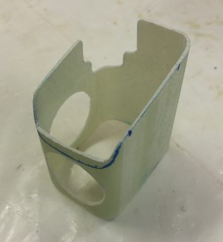
After some judicious sanding –mainly on the front angle of the armrest mounting bracket– I taped up the inside of the armrest and then 5-min glued the mounting bracket to the front face plate. I did this while keeping the face plate in its proper position at the front of the armrest.
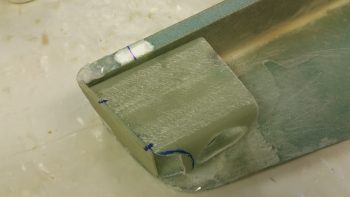
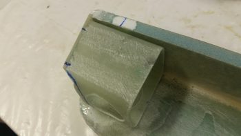
After the 5-min glue cured, I immediately glassed the bracket to the face plate with 1 ply of BID in the corners for each of the interior intersecting walls, using micro fillets.
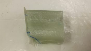
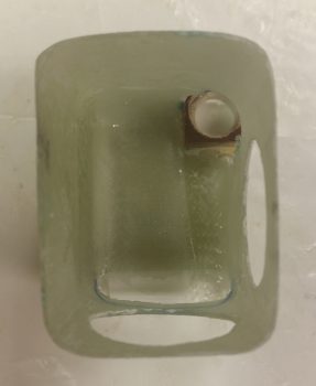
I then rounded up the left GIB mounting bracket’s nutplate assembly that I had made up a few days ago.
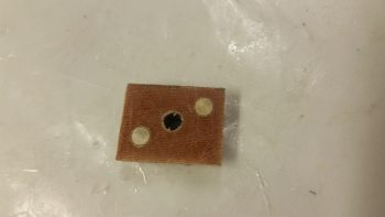
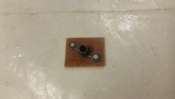
This time I taped up the edges of the face plate assembly in prep for these multi-tasked next steps.
I then laid up 2 more small plies of BID inside of the bracket: 1 on each interior side of the PTT button foam & phenolic mounting pieces.
I then floxed the nutplate assembly into place on the underside of the bracket’s top plate
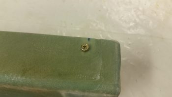
With the face plate taped, I also micro’d the edges of the face plate to fill in any gaps between the face plate and the armrest inside edge.
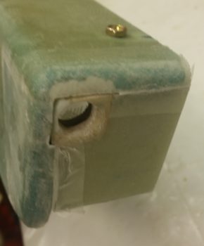
Here’s a shot of the floxed nutplate assembly in place on the underside of the bracket’s top plate.
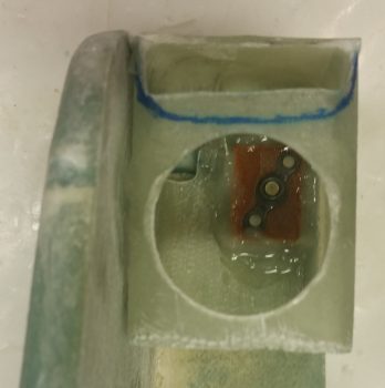
Here’s a shot of both the floxed in place nutplate assembly and the ply of BID on each side of the interior PTT button housing.
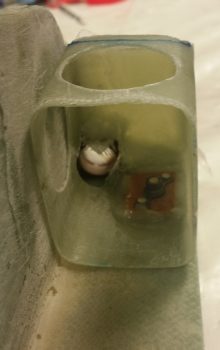
And one final shot of the ply of BID on each side of the interior PTT button housing.
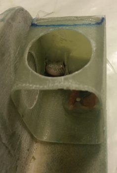
•••
7 July 2017 — Today I started out by cleaning up the 2 small layups that overlap onto the two internal sides of the PTT 1/4″ phenolic mount and the foam/flocro recessed PTT button housing junctions.
I then identified my desired positions for the headset jacks and drilled the two 3/8″ holes for those. I then of course installed the jacks to ensure they fit . . . which they did (yeah!).
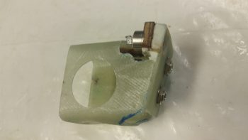
So, here’s the forward Left GIB mounting/PTT button/headseat jacks bracket that will reside on the front face of the left GIB armrest.
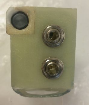
Here’s the business end showing the internal side of the bracket. Yes, it’s a bit tight in there, but it all fits fine.
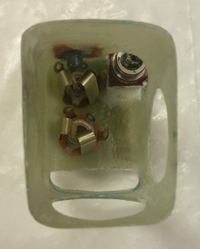
And here’s an “action shot” showing the armrest front faceplate set in place. I still have just a bit of cleanup work to do to get it all squared away cosmetically, but structurally –beyond actually installing it to the sidewall– I’m done.
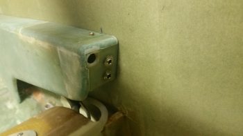
To verify that there were no clearance issues with the headset plugs, I took the bracket assembly upstairs and hooked up one of my headsets. Looks good!
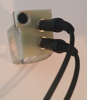
Here’s close to the actual angle that the GIB will experience when plugging in their headset.
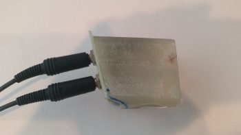
And from the other side.
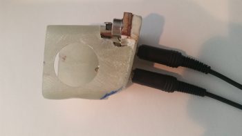
The internal clearance with the plugs installed is fine as well.
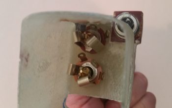
•••
17 July 2017 — I started off today by prepping the left GIB armrest forward mounting bracket for getting floxed to the left fuselage sidewall.
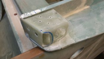
After mounting the forward mounting bracket to the left GIB armrest with its attach bolt, I then mixed up some flox and slathered it onto the outboard side of the mounting bracket.
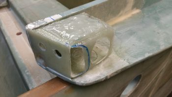
I then mounted the left GIB armrest into place, installing the 4 aft bolts into place to hold the freshly floxed armrest forward mounting bracket firmly against the fuselage sidewall.
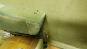
Later, after the flox cured, I removed the left GIB armrest to reveal the forward mounting bracket, which of course also serves as the GIB headset jack plate and PTT button mount. I had just a bit of flox leftover from the previous layups, so I used that to seal the perimeter of the flox on the bracket.
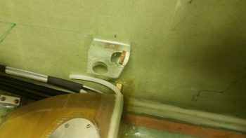
Here are a couple more shots of the left GIB armrest forward mounting bracket floxed in place.
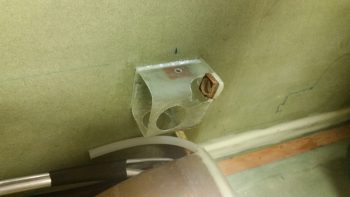
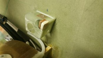
Here’s a pic of not only the left GIB armrest forward mounting bracket floxed in place, but also the two 1/2″ oil heat lines that I mounted earlier.
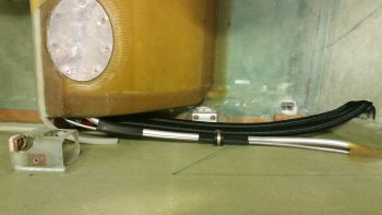
I had also cut out a 0.5mm piece of aluminum (from my German stock) to use as a hardpoint for the midpoint attachment of the right side storage pocket to the right GIB armrest. This setup is simply to reinforce the midpoint glass so that it won’t crack under the pressure of the countersunk screw that will be mounted.
I then floxed the aluminum piece in place and covered it with 1 ply of BID using the epoxy that I had made for the layup above. I then peel plied this layup as well.
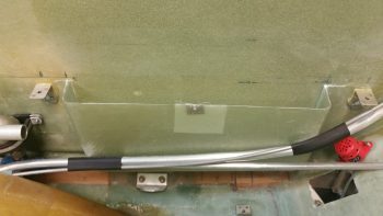
•••
18 July 2017 — Today I cleaned up the layup on the right armrest midpoint hardpoint layup. I then set the countersunk screw in place so that it would be visible by the camera.
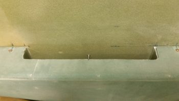
I then installed the screw completely to show the screw’s low profile. If you’re wondering where the screw is located, look at the small mark at about the midpoint of the edge of the storage pocket.
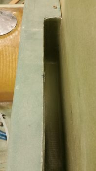
I then took about 15 minutes to mark and cut the right armrest storage pocket lid hinge. I then mocked it up in place by taping the hinge to the fuselage sidewall.
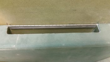
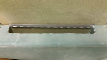
•••
21 July 2017 — Today I started working on the G10 Garolite lid for the right GIB armrest storage pocket. After I trimmed and sanded it for a bit, I was able to set it in place on the very slight lip that I created on the inside edge of the armrest storage pocket cutout.
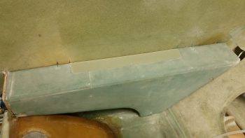
•••
11 August 2017 — I started off on the actual build by drilling a few sets of tiny holes to inject fresh epoxy into some air bubbles along the joint of the front extension pieces that I had glassed onto the left GIB armrest. This armrest is definitely the ugly duckling of the armrests, and admittedly looks pretty nasty where I glassed the front extension pieces into place (I was originally planning on having a throttle handle back here, but then realized first that it was located too far aft, and then second, that I simply wasn’t going to install one).
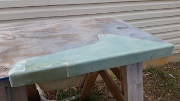
That’s why it’s so cool, and so much fun honestly, to see it turn out like this with just a few passes of a primer spray can.
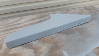
I let the primer cure for a few hours, cleaned up and sanded a few minor imperfections, then shot two coats of the gray granite interior paint.
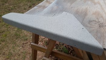
I then let the topcoat cure for about 6 hours before shooting it with a couple coats of matt clear coat. A little over an hour later, when it was dry to the touch, I set it in place to get the pics below.
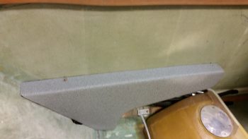
I have to say, I’m really digging this color. It’s not super flashy nor does it make a huge fashion statement, but it really does look good. And of course, as I often state, the pics don’t do it justice.
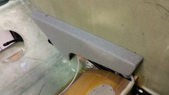
•••
17 September 2017 — Today I trimmed the bottom of the right armrest to provide clearance and eliminate any rubbing on the fuel lines.
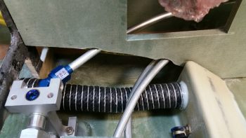
I also notched the bottom center of the left pilot armrest with a triangular opening to allow the armrest wall to fit over the pilot thigh support wedge duct when installed. I also had to narrow the thickness of the wall on the outboard side of it that was adjacent to the air vent plenum duct in order for it to fit in its planned location.
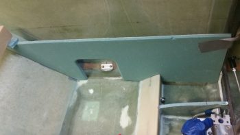
•••
18 September 2017 — Today I set the freshly constructed pilot seat thigh support floor in place, threw a towel and some padding on it, grabbed my throttle handle quadrant and climbed in.
This first shot is exactly what I was aiming for! The fuel selector valve is aft enough and high enough that I can actually easily see it and manipulate it during flight! Hoo-ah! Also, I should point out that my fuel selector valve bracket is only about 1/2″ max total farther aft than the stock plans fuel valve plate. The difference: my valve is located at the very aft end of the plate, obviously about an inch higher, and not located center of mass on the valve plate as the plans valve is.
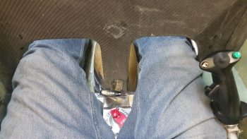
I then mocked up the throttle location to test it out. I messed about with the throttle for a bit and determined that for me I had in fact picked the optimum location for this throttle quadrant setup.
Here’s a shot of the throttle handle/quadrant, fuel selector valve and control stick. Again, I’m extremely satisfied with the location, ergonomics and functionality of all these controls!
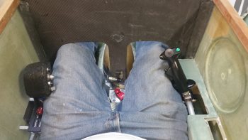
And here’s my parting shot of this post. The throttle handle and quadrant in its planned left armrest location.
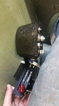
•••
6 November 2017 — Since it was yet another unexpectedly warmer day for this time of year, I spent a bit of time in-between my tasks prepping the right pilot armrest for paint. I wasn’t sure if I was going to be able to squeeze it in, but I eventually got a shot to get it outside, get a couple light coats of primer on it, and then hit with a couple coats of the granite gray about 45 minutes later.
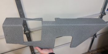
•••
7 November 2017 — I really didn’t get a lot done in the shop today since the weather was forecasted to be about 70° F and overcast… instead it was in the mid-40’s and raining. Clearly not a good day for painting. Well, since I was so close on the right armrest, I decided to clear coat it in the shop, then I headed out for about 4 hours running errands and stocking up on Nitrile gloves and other shop consumables while the concentration of fumes died down a bit. When I returned, I was quite pleased with the clear coating results!
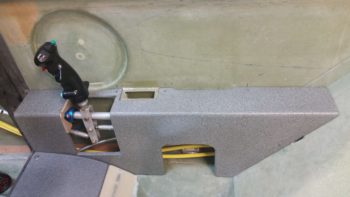
•••
14 November 2017 — Today, since I had the sheet of 0.040″ thick 2024 aluminum out, I went ahead and cut the 3.3″ x 3.5″ plate for the 2 “Mag” switches (we’ll say, although both are electronic ignition) and the master switch. As you can see by the pic, these switches will get mounted just forward of the control stick on the right armrest.
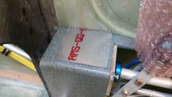
•••
31 March 2018 — Today I finalized the install of the right side flight controls to the mini-bulkheads in the front and GIB side consoles (CS109 & CS118). I gathered up all the hardware per plans and then bolted the bearings in place, again to the CS118 mini-bulkhead aft . . .
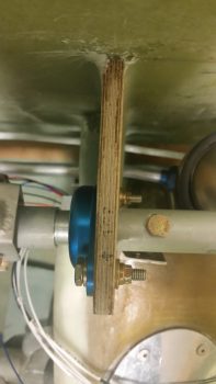
and to the CS109 mini-bulkhead up front. I’m using the Cozy Girrrls control system hardware, so their bearing assemblies at each end of the control tubes may be less thick than stock, because the AN3-7A bolts called out for in the plans are a bit too long in my book. But again, they work and the control system is installed, so a short thought to ponder.
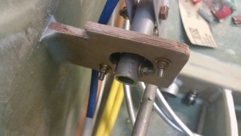
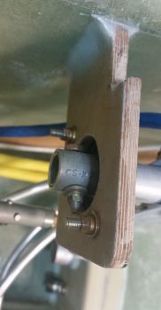
•••
1 April 2018 — Today I installed the CS123 control system bearing into the firewall. I lined up the aft end control rod with the one that runs along the fuselage sidewall, mixed up some rather wet flox, and then floxed in the CS123 bearing (this is a Cozy Girrrls product btw).
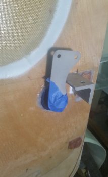
Here’s a slightly lower angle shot. I also got up into the hell hole and added a flox fillet around the front side as well. I don’t this thing will be going anywhere with as much flox that’s holding it into place!
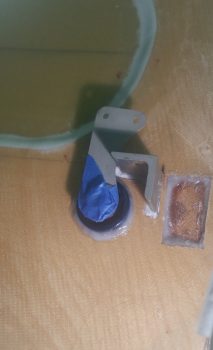
•••
2 April 2018 — I started off today by pulling the protective tape off the components of the CS123 control bearing floxed in place on the firewall.
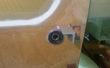
Here’s a closeup of CS123 floxed into the firewall. I realize (yes, after looking at my notes!) that there was a reason I was waiting to do this, and that the plans have you install the actual firewall Fiberfrax and metal sheet in Chapter 15. Well, I was in Chapter 16 . . . oh, well. There’s definitely a 6 and 1/2-dozen thing going on here because I really wasn’t ever keen on floxing this thing to a metal covered firewall. So I’ll deal with the minor inconvenience of mounting the Fiberfrax and firewall sheeting over top and around my floxed-in CS123 bearing.
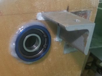
Here’s another shot with the aileron control tab slid into place. A couple things on the elevator control tab . . . if it looks closer than it should to the lower right engine extrusion, it is. First off, that’s because the engine extrusion is 1.25″ wide vs. the plans’ 1″ wide. Thus we’re clearly missing 1/4″ clearance that would normally be there. That clearance will be attained from both sides giving a little: 1/8″ to be exact. If you look at the extrusion, the majority of a 1/8″ trim on the edge would be primarily in the tapered edge area of the angled piece of aluminum. On the aileron control it will just be a rounded little notch that is carefully made in the tab.
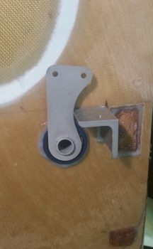
•••
16 April 2018 — On my recent trip down to Chesapeake, Marco was gracious enough to do a bit of machining for my build and lathed the midpoint quick disconnect insert bar on what will be my new elevator control tube [If you remember, I drilled an “extra” hole in my other one and didn’t want to fly with it with an unnecessary hole that only would serve to weaken a critical flight control component. Moreover, Chris Seats gave me some info and components to help me upgrade to a 5/8″ diameter tube vs the 1/2″ stock… not that the stock version is deficient, it just happened to be easier for me to build a 5/8″ version].
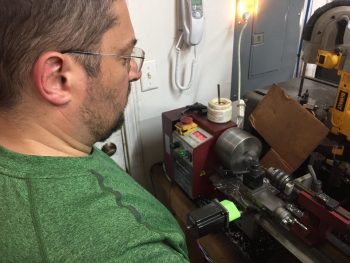
Marco lathed the midpoint quick disconnect insert bar from a 5/8″ rod of 2024 aluminum down to just a bit of over a half inch in diameter. We also cut it to length to allow for not only the quick disconnect clevis pin(s) & rivets to be mounted, but also long enough that the new (and correct) pitch trim actuator connecting hole will now be drilled through both the control tube and the lower side of the quick disconnect insert bar… clearly a much stronger mounting hole since it will be solid metal for the entire width of the hole. We then cut the new 5/8″ control tube pieces to length.
•••
17 April 2018 — Today I got busy assembling the new 5/8″ elevator control rod that would replace the old one that I so haphazardly decided to drill an extra hole into. I used some larger rivets that Chris Seats gave me and got busy drilling and mashing rivets! Here’s the assembled product.
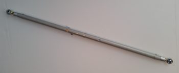
Here you can see the internal rod that Marco lathed down the diameter of and cut to length. We of course cut the 2 main tubing pieces to length as well. Since I have so much real estate on the top end of the quick disconnect internal solid rod, I’m going to drill an extra #10 hole and actually install an AN3 bolt and nut in addition to the clevis pin.
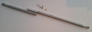
Here’s a shot with the Atkinson pitch trim actuator bolt slid into the bolt hole that I drilled on this new 5/8″ elevator control rod. Again, the internal solid rod that makes up the quick disconnect also extends down beyond the pitch trim actuator bolt hole so the hole is much more robust than on the previous elevator control rod.
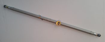
And here’s a view of the other side of the pitch trim actuator connecting bolt.
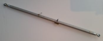
•••
19 April 2018 — Today I decided to finish off the elevator control rod by drilling a #10 hole and mounting an AN3-7A bolt into the hole (IRRC this is a Ken Miller mod….). The bolt will be in addition to the clevis pin that secures the forward side of the elevator control rod to the aft side.
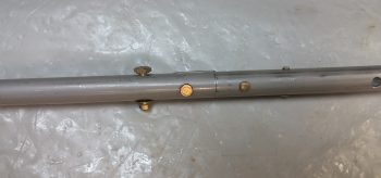
•••
24 May 2018 — Today I got the canard down off its perch and mounted it to the fuselage. The mounted canard will provide some data on the final nose build and also facilitate finishing some prerequisite nose tasks before starting in on the nose and canopy builds proper.
I tested out my new 5/8″ elevator control rod that appropriately enough only has ONE hole for the pitch trim servo arm attach (Just say NO to extra holes!).
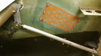
I then rounded up some scrap 3/8″ PVC foam that had a ply of BID glassed to each side and used it as the elevator up-travel control stop. I whipped up a small amount of flox with fast hardener and also used a small dab of 5-minute glue to secure the control stop to the right fuselage side wall. As you can see, I used the actual elevator control arm as a sort of jig.
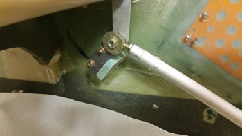
The way I knew the elevator control arm was in the right position was by using the elevator angle template to ensure I was at the max 15° elevator up travel. I’m actually just a hair lower than I can get the elevator to travel, but any higher up and it starts to contact the canard TE, so this is a good position for the elevator control stop.
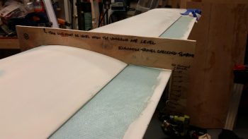
Since I had access to the aft side of elevator control up-travel stop, I laid up a ply of BID with the requisite flox fillet.
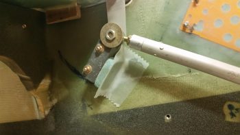
•••
25 May 2018 — Today I prepregged 1 ply of BID and 1 ply of UNI to layup on the forward side of the elevator up travel control stop. I decided that this would be strong enough with just the foam tab piece sticking out 90° from the sidewall and scrapped glassing in the perpendicular triangular piece that I had cut for this setup. I then of course peel plied the lay up.
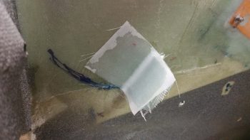
A few hours I pulled the peel ply and trimmed up the edges. Nice and simple, and strong, and it worked a treat!
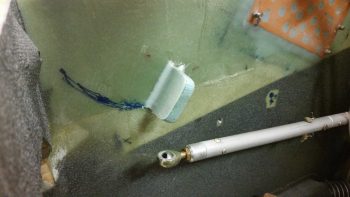
•••
19 August 2020 — Today I got to work on the GIB right armrest storage bin hinged cover.
I first needed to notch the outboard edge of the cover to allow for the hinge assembly. As you can see I used my small bandsaw for this task.
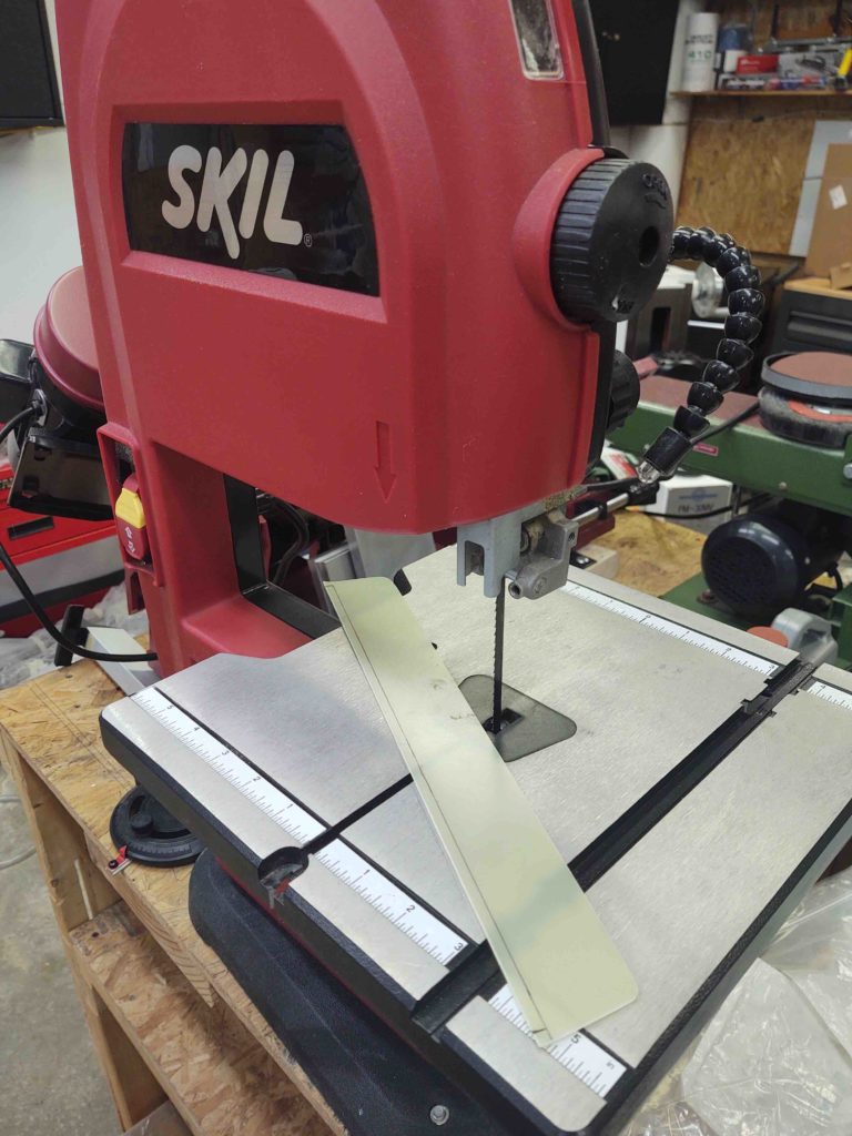
And here’s the result.
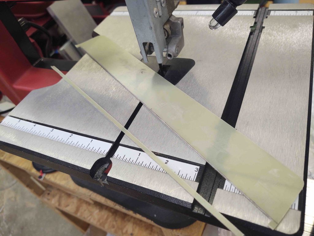
After filing and sanding the above edge straight and smooth, I then drilled some flox holes into the lower hinge half, and then drilled rivet holes in the cover and upper hinge half.
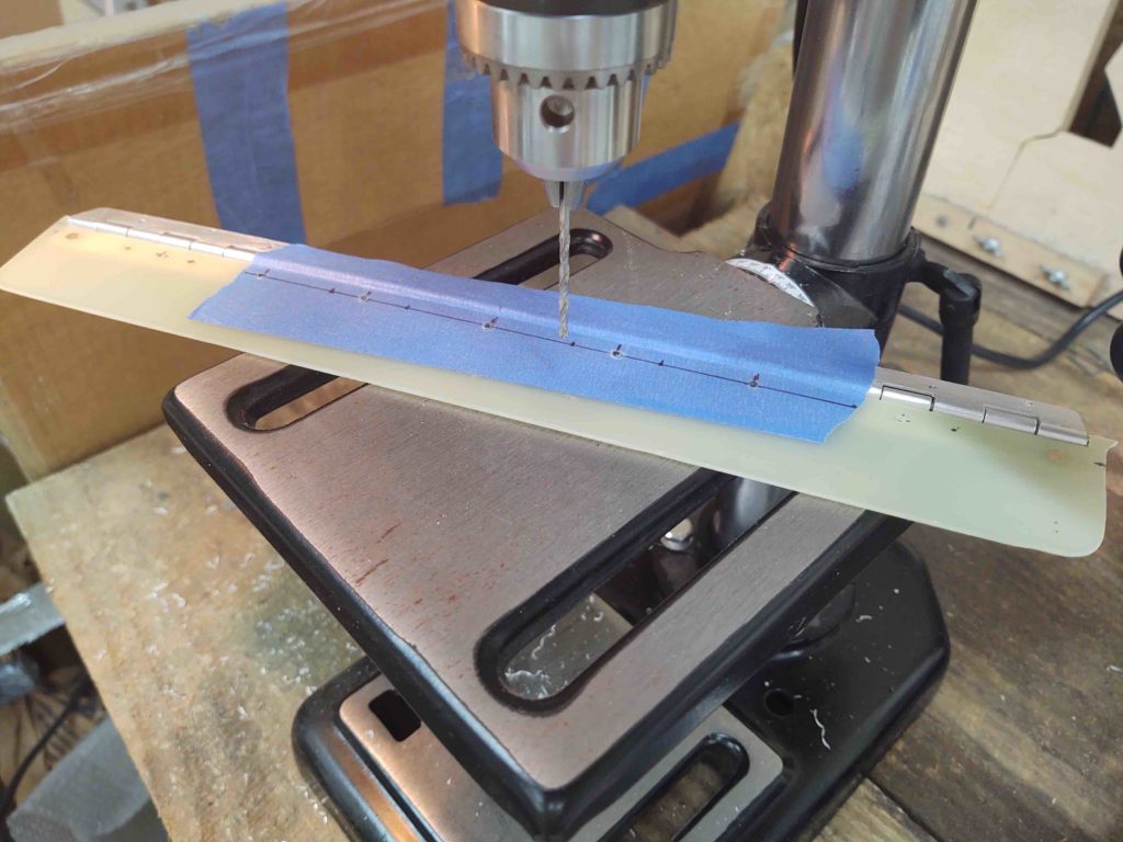
I then riveted the cover to the upper hinge half.
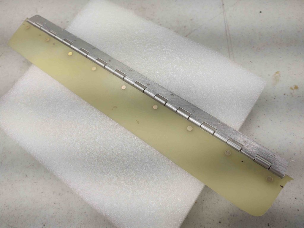
An underside view.
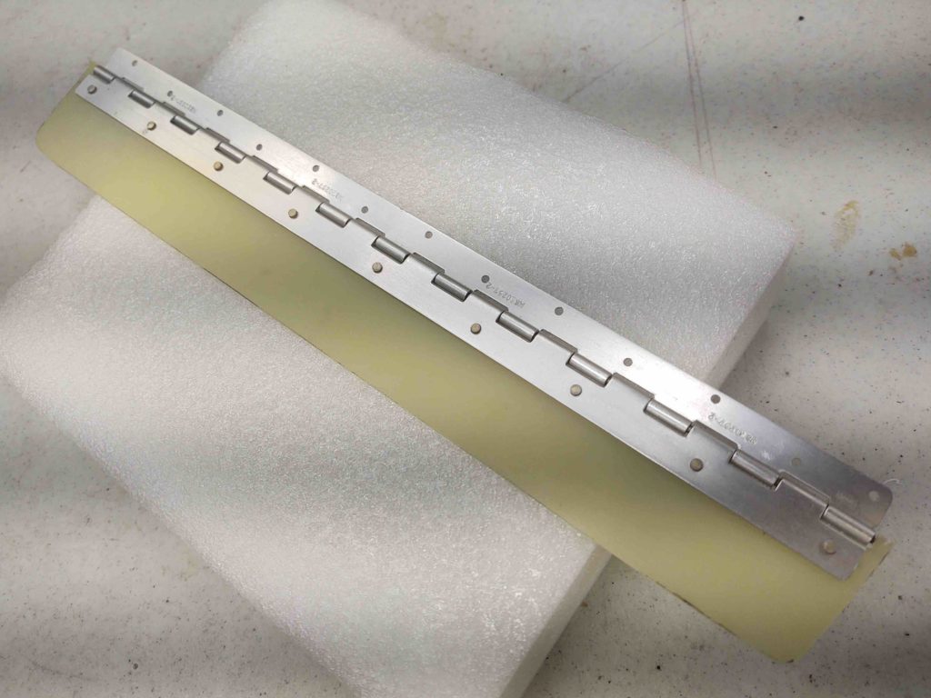
Then using flox and a few dabs of 5-min glue I floxed the lower hinge half onto the right fuselage sidewall.
I Gorilla-duct-taped popsicle sticks to the top of the cover overhanging onto the armrest top to create an even plane between the cover and armrest surfaces. I then weighed the edges down with my drills, etc. to ensure it all stayed flat and even.
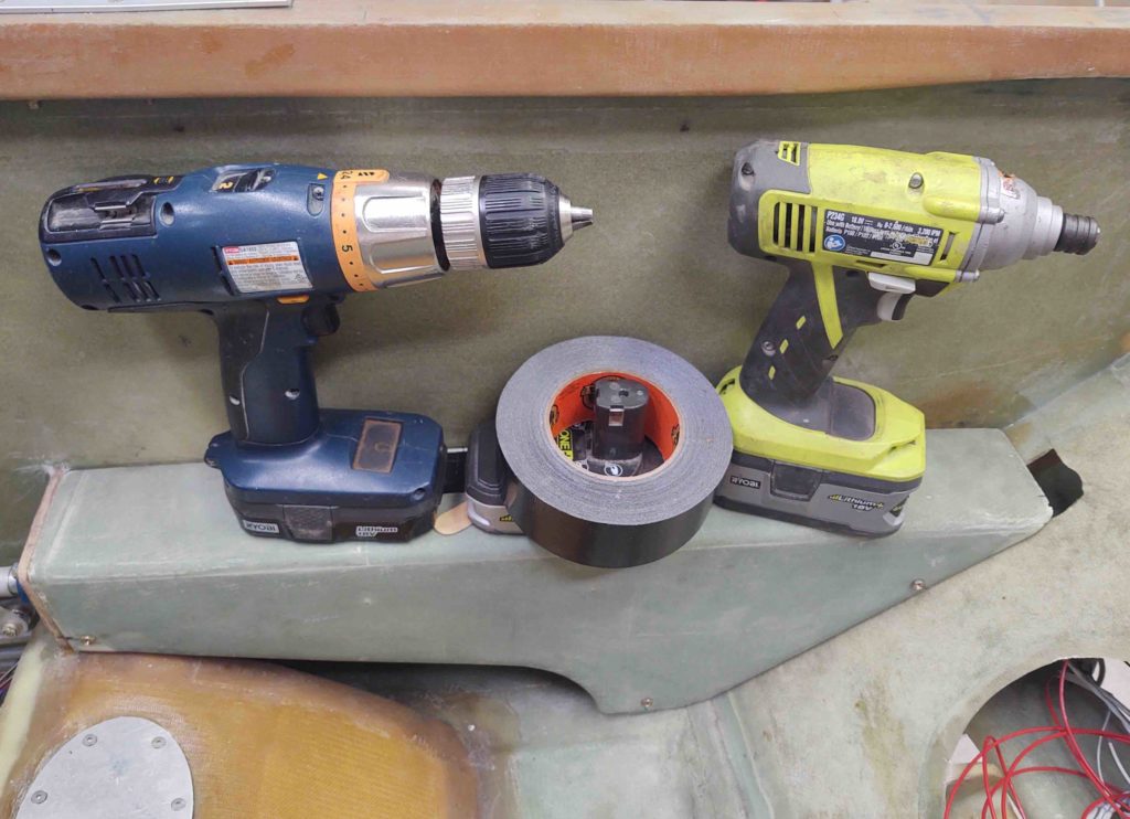
I then got to work installing a Bose headset LEMO jack for the GIB. I thought about this a bit late last year and figured if I was ever going to use a Bose headset for the back seat –which I intend to– then I should install the LEMO jack before I build the strakes… after which working in the back seat area gets infinitely more difficult.
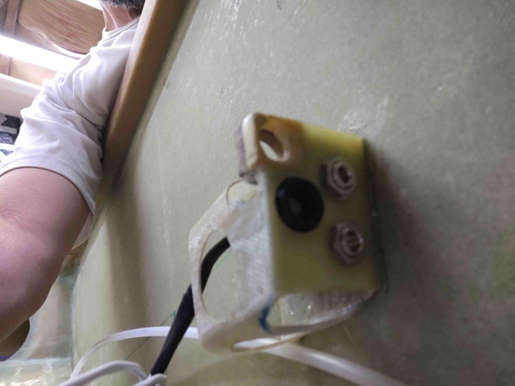
The installation hole isn’t perfect, or overly high craftsmanship, but it works and fits, and looks to be a secure installation. . . so I’m calling it a win. Especially since it just barely fit in there with the existing traditional headphone jacks.
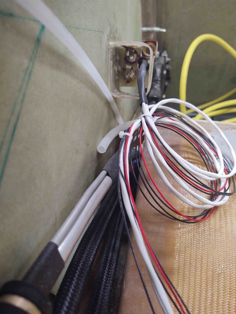
to cap off the evening I unencumbered the top of the GIB armrest storage bin cover and removed the tape to reveal how it looks. I have to say that I’m super happy with how it turned out.
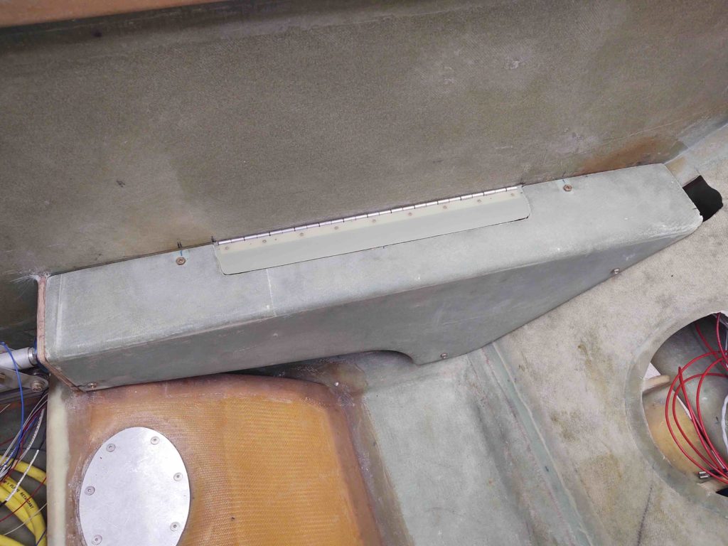
And of course a shot with it open… ready for business!
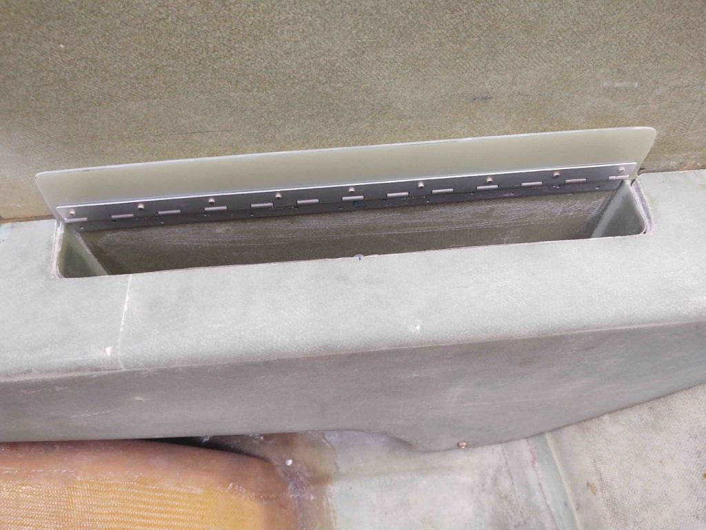
•••
21 October 2020 — Today I wondered off my assigned heading a bit with an impromptu arts and crafts project. Sometimes that wild hair just gets you, and today it was labeling the control stick. It ended up being over a 3 hour detour (whoops!).
I already had a few labels on it just to test out the label size and attachment, and with these labels on a few years (grant it, not under constant operational use) I figured I would charge ahead with the rest of the labeling. So I’m calling this labeling Round 2.
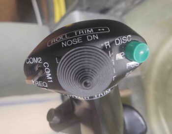
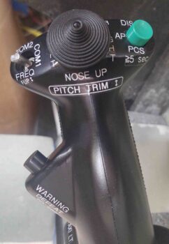
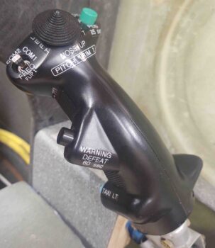 I had two issues with the round 2 labeling, one minor, one major. The minor issue was the font size was a little too big in a lot of areas and made it look a bit gaudy to me.
The more major, critical issue was that I sent the pics of my control stick round 2 labeling shenanigans to Marco. Critical mistake! ha (Just kiddin’….) With him being a professional pilot, I was quickly informed that airline standardization would have the autopilot disconnect on the side where my temp warning defeat button (black) was currently located. Moreover, the button should be red. This latter recommendation was on my to-do list anyway, but I really do appreciate Marco’s input, since he’s been involved with a lot of human factors training with the airlines and I want to be as safe as possible (thanks again Bro!).
Thus I tweaked my labeling yet again, primarily swapping the autopilot disconnect with the temp warning defeat button. I also took this opportunity to replace a bunch of labels with the smaller font. I really do think it helps reduce the gaudiness of the stick.
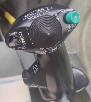
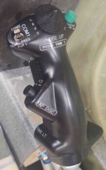
A bit later when I went back into the house, I dug around and found my Infinity Aerospace box and grabbed a red and gray button to swap out.
This is the final mod (so far) that I made on the control stick:
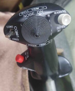
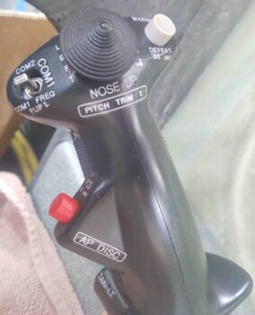
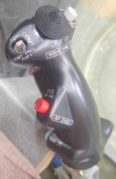
•••
23 October 2020 — I had printed out some new labels for the control stick yesterday, so first thing today I got them off the work bench and on the control stick so they wouldn’t get lost… here it is. Not much difference, but a few smaller labels (e.g. “COM1”).
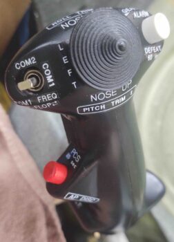
•••