
Chapter 24 – GIB Sub-Panels
This page covers the pair of GIB sub-panels situated just aft of the upper pilot seat, one on each side.
11 November 2020 — Today I got busy mocking up the GIB area side panels. I don’t really like side panels back here but do need a place to mount stuff.
To minimize their footprint as best possible, I angled them so that the inboard edge was down/forward. This helps only a skooch, but I’ll take what I can get.
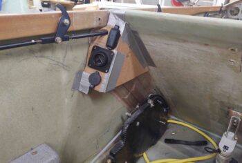
Here’s the left side GIB sub-panel, replete with an eyeball vent and a couple of chargers (USB and cigarette style):
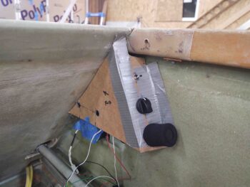
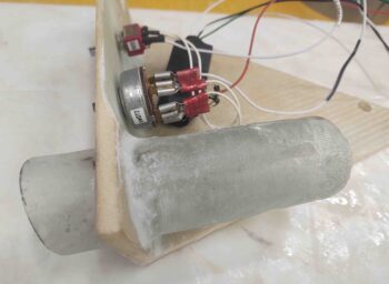
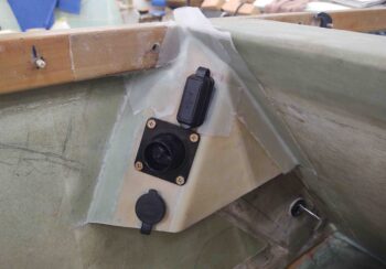
And here’s the right side, with a switch for red or white colored lights, and rotary selector for floor lights, reading/map light, or both. Finally, we have a storage spot for the control stick handle, although it will be bit further into the sub-panel face than is shown here.
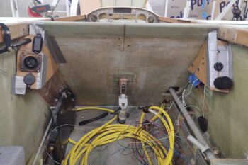
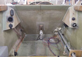
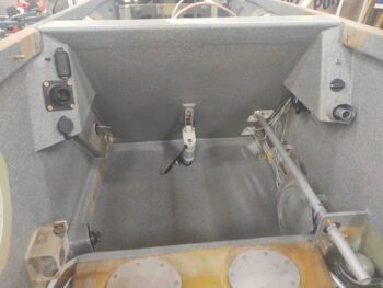
Here’s a shot of both GIB sub-panel mockups.
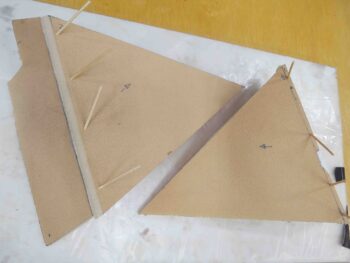
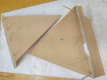
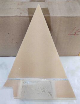
I then spent a good bit of time cutting 1/4″ thick foam to make up the left and right GIB sub-panel basic structures. I then micro’d the respective faces to the respective sides and secured the pieces together with toothpicks… leaving them to cure overnight.
•••
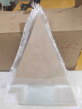
12 November 2020 — I got into the shop to layup a ply of BID on each of the GIB area side sub-panels. I then peel plied the layups.
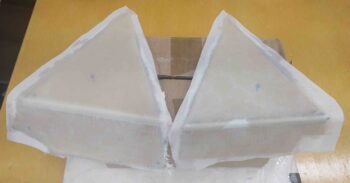
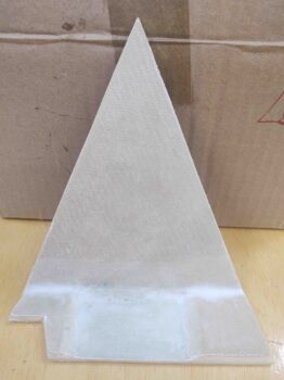
Later in the evening, after the layups had cured I pulled the peel ply and razor trimmed the GIB sub-panels.
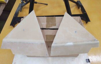
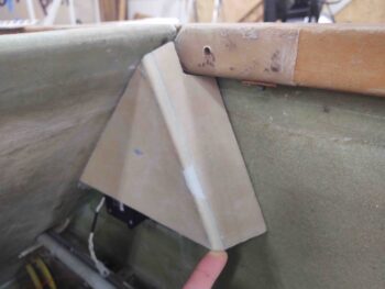
I then set them in place for a quick test fit and pic of each. The left side is jammed up against a cleco so it’s not fitting quite as tight as it will when actually glassed in place (or so I thought . . .).
•••
13 November 2020 — After assessing the required panel thickness for the 2 switches (one toggle, one rotary) that I’m mounting on the left side GIB sub-panel, I thinned the foam out in the spot where the switches will go.
Since this foam is only 1/4″ thick to start, I took it down around 0.1″ of foam left. Unfortunately, I ran out of time and didn’t get to glass the interior side of this sub-panel.
•••
17 November 2020 — Today I glassed the interior of the right GIB sub-panel. I used an added ply of BID on the depression where the 2 switches will get mounted, and then used a couple of overlapping scrap plies of BID for the rest of the interior surface.
My friend needed me to watch her kid for a few hours, so my little buddy came over to hang out. I was just finishing up the layup above, and was able to get the interior of the left GIB sub-panel shaped (sorry, forgot to get a pic). I’ll glass that sub-panel tomorrow.
I did get back out to the shop later in the evening to pull the peel ply and razor trim the right GIB sub-panel once the glass had cured.
•••
19 November 2020 — I finally got around to pulling the peel ply and cleaning up the GIB right sub-panel interior layup.
I didn’t have a pic of this earlier, but this is the storage tube for the GIB removable control stick.
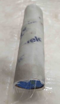
I actually took a cardboard tube and wrapped it around the GIB control stick, and then taped it up.
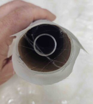
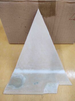
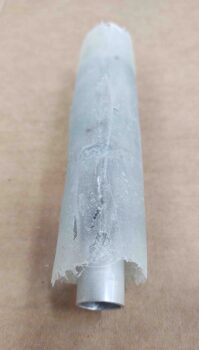
I then laid up a bunch of small pieces of scrap glass onto the taped tube, and peel plied it. Here it is with the peel ply removed.
And with the taped, and untaped, control stick removed.
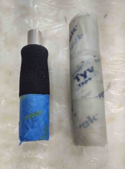
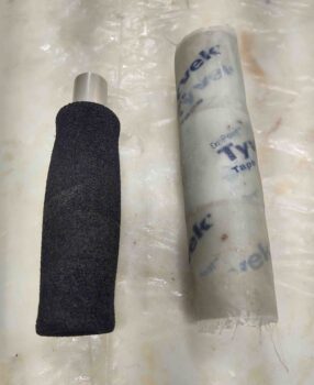
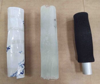
Here’s the taped cardboard tube form, the GIB control stick stowage tube, and the GIB control stick.
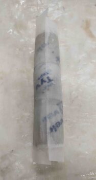
Here we have the GIB control stick in the stowage tube.
•••
20 November 2020 — I laid up a ply of BID on the back of the GIB control stick storage tube as a stop to keep the stick from sliding in too far..

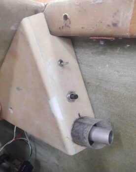
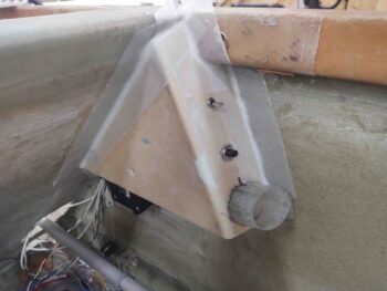
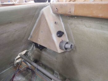
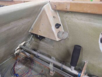
I then spent a good hour+ floxing the GIB removable control stick storage tube into the GIB right sub-panel. I used a good bit of micro as well and a few plies of BID to secure the stick storage tube.
Here’s another shot.
I then mocked up and test fitted the GIB right sub-panel. Again, if you’re wondering why I went through the trouble of making a storage tube for the GIB control stick, it’s because I don’t like “gear afloat” (as the Navy would say) in the cockpit.
In fact, there’s a funny story (now) of me in the back of Marco’s Long-EZ trying to maintain a climb as Marco punched in waypoints in the GPS. He asked me what was up since my climb was quite anemic and we were at risk of overspeeding the prop.
Well, as I was moving stuff around in the back seat, the control stick fell out of the strake baggage area onto the floor: game over. There was no way I could retrieve it… my climb angle was so weak because I was using my finger in the control stick nub trying to lever it back as far as possible. Unfortunately my finger didn’t work as well as a stick handle!
•••
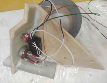
21 November 2020 — For the GIB right sub-panel I ran 2 sets of wires: The first went out the side wall to power/control the GIB map light. The second was the GIB lights power and ground wires that go forward to the TriParagon.
Also note that I 5-min glued the relay to the interior side of the right GIB sub-panel. I then had a small strip of 1-ply BID left over from the ELT antenna backplane layup, so I used it to help secure the relay to the inside surface of the sub-panel, just behind the switches.
My last task of the evening, as it was getting late, was to 5-minute glue the right GIB sub-panel into place. As you can I secured it in place (after holding it in place for quite a few minutes) with Gorilla duct tape.
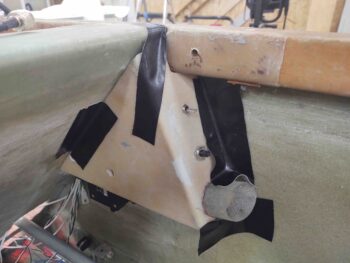
I then let the 5-minute glue cure overnight.
•••
22 November 2020 — I started by laying up 1-ply BID tapes on the perimeter of the GIB right sub-panel to secure it into place. I then peel plied the layups.
I then worked for a number of hours on the final configuration of the LEFT GIB sub-panel. I had to flatten the install angle of the USB charger to align it more parallel to AC centerline to get better clearance with the canopy latch rod. I also made up 4x 10-32 phenolic nutplate assemblies and mounted them on the underside of the sub-panel for the eyeball vent-securing screws. Again, I was in such a mad rush to get all this done that I failed to snap any pics.
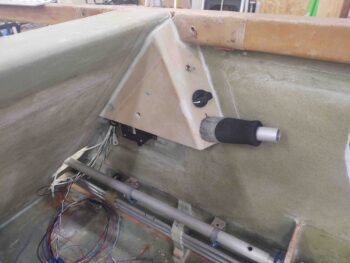
Before I got around to glassing in the LEFT GIB sub-panel, I pulled the peel ply and cleaned up the layups on the right GIB sub-panel. Here it is with the GIB removable control stick in the stowed position.
And a shot with the control stick nearly out of its stowage tube, to show that I made the diameter of the tube just a tad smaller than the diameter of the foam grip on the control stick so that the tube grips the control stick firmly.
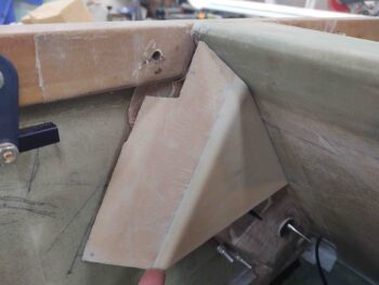
Although I removed the control stick assemblies in prep for paint, here I’ve mocked up the GIB control stick in place. I’ll note that I tested and double-checked the clearance between the control stick, and during use, with the aft lower edge of the right GIB sub-panel.
While I’d say I’m very happy with the right side GIB sub-panel, I’d say I’m somewhathappy with the left GIB sub-panel. I’ve already stated in practice I’m not a big fan of these side sub-panels, and if it weren’t so late in the game and I hadn’t set the position of the upper GIB air/heat vent via the main duct system, I’d have reworked this side sub-panel, especially after this last issue.
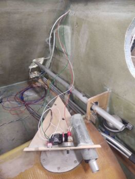
My mockups went well, but it’s hard to tell exactly how all will fit until the rubber meets the road when you do the final install. With the clearance, or lack thereof, with the components and especially the interconnect SCAT tube from duct to eyeball vent, to keep the inboard wall of sub-panel vertical and not angled inboard I had to come off the sidewall over 1/2″ (note the strip of green 0.063″ G10 that I 5-min glued, floxed and glassed in place). Again, this late in the game I was just not going to redo this panel and start over… my decision was to salvage what I had and press forward. And yes, it does translate into a little less knee room for the GIB.
My first issue was the angle of the sub-panel face is a good 5-10º too steep off the sidewall. I should have made it more perpendicular to the sidewall. By not having a shallower angle it made the components face too much outwards vs parallel to AC centerline. This had them pressing into the duct and minor clearance with the canopy latch rod. I expected to have to bring the sub-panel off the sidewall about 1/4″ max, but not over 1/2″.
[Note: during the layups the USB charger cap is not in place, but hanging down farther than normal. This makes it look like its both installed closer to the eyeball vent than it actually is, and also off-kilter in the last pic. Future pics will show this better.]
My blog post title, “function over form” alludes to the placement of the components in the sub-panel. I didn’t just throw these chargers and eyeball onto the face of the sub-panel willy-nilly, but rather had to configure them to avoid what lurks underneath: the alignment of the eyeball vent with the duct behind/underneath it, and the vertical & inboard placement of the USB charger to keep it from interfering with the canopy latch rod. A horizontal placement of the USB charger was out of the question, and if I tried to move it up any higher it would collide with the aft surface of the pilot seat back.
So it is what is, functional but not perfect. I’ll throw some lipstick on this pig by painting it and press on…
Ironically my buddy Dave Berenholtz recently commented on how nice I was being to the GIB by installing a bunch of this stuff, so I guess just to prove him wrong I extracted some knee room from them! (grin).
•••
24 November 2020 — Here’s a shot of the GIB sub-panels after getting painted and clear-coated.
•••
25 November 2020 — Tonight I put the seat cores back in place place in the fuselage to do one thorough final assessment of how they fit before I send them back to get upholstered.
This also gave me a chance to do a quick knee clearance assessment on my GIB side sub-panels. I’ll remind ya’ll that I’m a long-legged 5′ 11″ tall, so I consider myself right at the max height for someone to travel comfortably in my back seat on a longer trip. Any shorter heights than me should be fine comfort wise.
With my feet placed at a comfortable mid-point on the floor board, my knees are actually behind the sub-panels and rest quite comfortably on the fuselage sidewall.
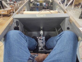
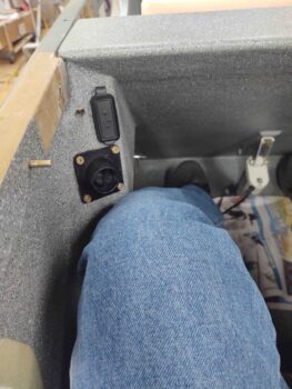
However, if I move my left foot forward to just aft of the pilot’s seat, my leg just below the knee rests on the edge of the left side sub-panel. It’s not horrible nor is it digging into my leg, but I wouldn’t want to keep my leg at this position for a considerable length of time. Not optimum, but not horrible either.
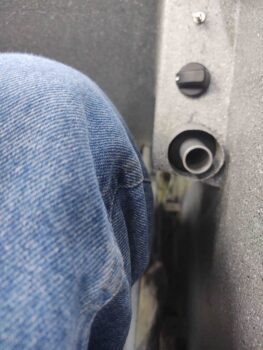
Conversely, the right sub-panel is no factor since it is narrower than the distance that the control stick tube is from the sidewall. Thus, my leg rests against the control stick tube before it makes contact with the edge of side panel. Clearly this what I had envisioned for both sides, but the left didn’t make the grade.
•••