
Pilot Headset Jack
(Note: the actual wiring will be under Chapter 22 – Electronics)
21 August 2020 — After a lengthy discussion with Marco a week ago, including him flying with his freshly moved headset jacks (over his right shoulder… previously on panel above his right knee), I decided to press forward with my planned install location at the junction of aft right armrest and seat back.
This spot will provide a very short run for all wires (<12″) and will all me to keep the bracket installed and still remove the right armrest whenever needed.
A couple of notes on this headset jack housing: First, it started off in life as a bracket/housing for the antenna cables/jacks exiting the canard. I had planned on mounting the antenna cables in it with the housing then mounted to the canard. My failure in accounting for the slope of the canard vs the flat bottom of this housing didn’t bode so well for it to work as intended.
Next, I had drilled 2 holes in it at some point. I can’t remember why. Clearly before I decided to add a Bose LEMO connector to the mix. I need 3 holes total: 2 traditional headset jacks and one LEMO. So some hole filling was required.
Lastly, I had lopped off the flange on one side, again I don’t remember why.
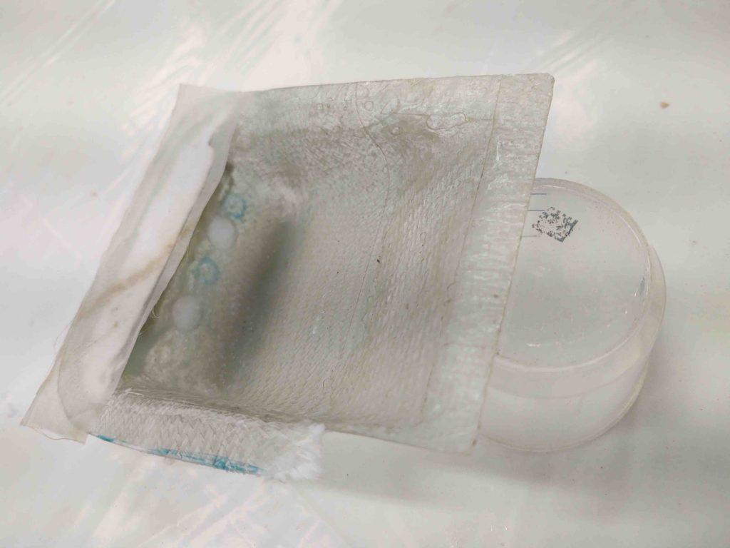
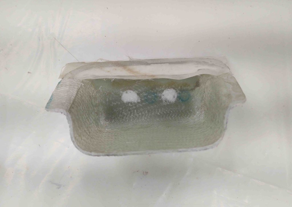
Thus, I used a small piece of my “newfound” urethane foam, shaped it at the bottom to create a more straight transition at the top/front, added a bit of duct tape to both hold the small foam piece in place and create a small radius to give me a lip for future mounting… and then simply slapped 2 plies of BID over all that.
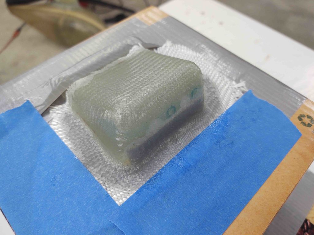
If my experiment here fails, I’ll simply design a headset jack housing in CAD and 3D print one… or at least a mold for one.
So far it seems like this should do fine…. more to follow.
•••
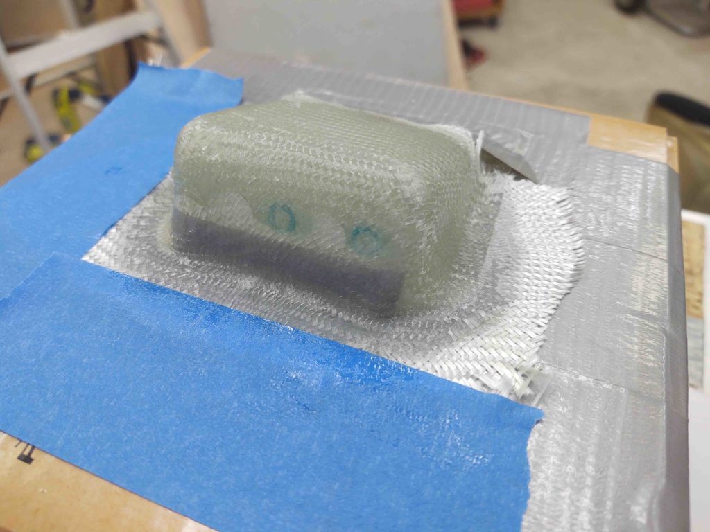
22 August 2020 — More work on the PIC headset jack cover . . . Here it is after I removed the blue tape.
And again after I trimmed up the glass edges… not too shabby.
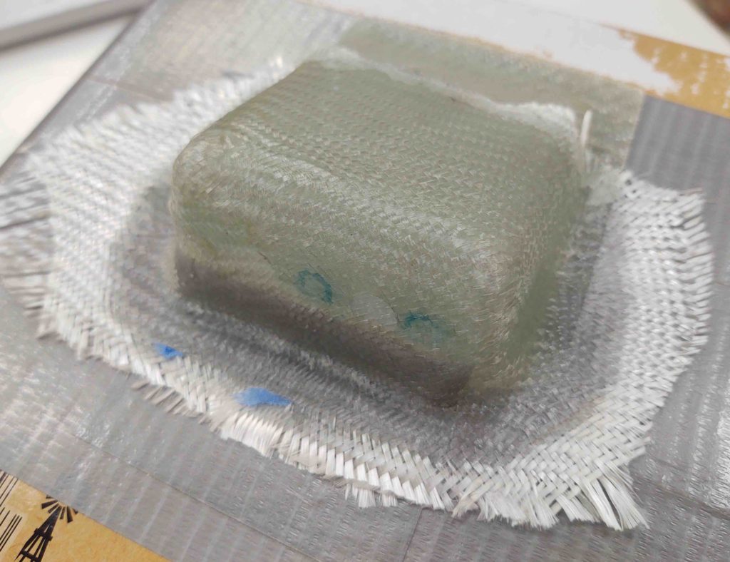
I cleaned out the thin sliver of shaping foam and the duct tape, sanded up the inside and small gap along the front and then attacked it again with micro and a ply of glass on the inside. Just enough to cover the front face with the existing hole indentions (to be clear, which I filled with micro).
A few hours later I measured the angle between the front right armrest and the pilot’s seatback. I then transcribed that angle onto the mostly cured PIC headset jack cover.
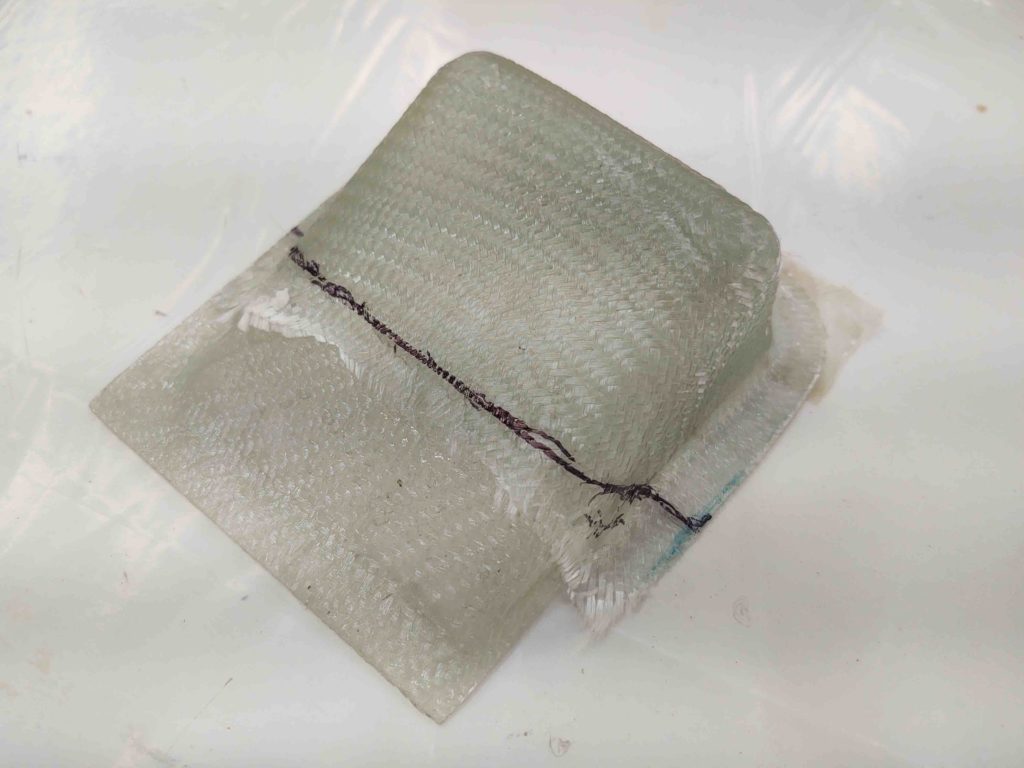
I then cut off about a third of the PIC headset jack cover.
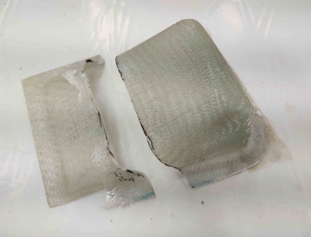
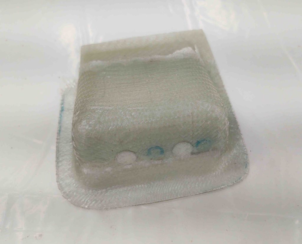
Although the peel ply is still covering the micro on the bottom, here’s what it looked like at this point.
And a shot of the very nearly cured interior 1-ply BID layup.
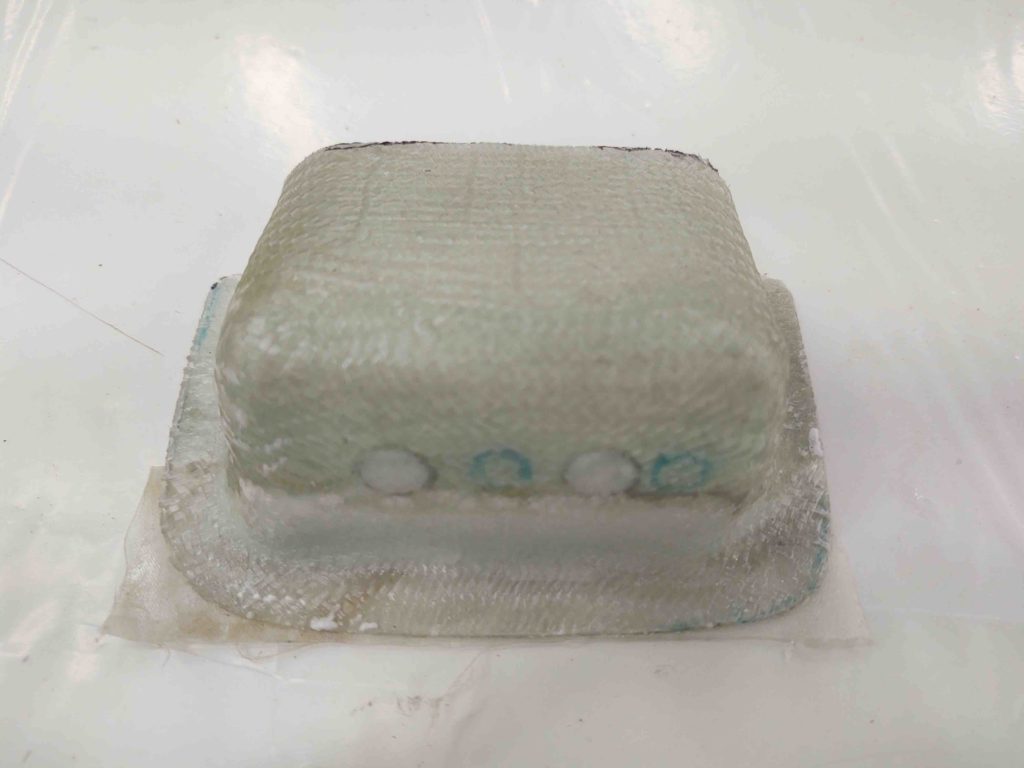
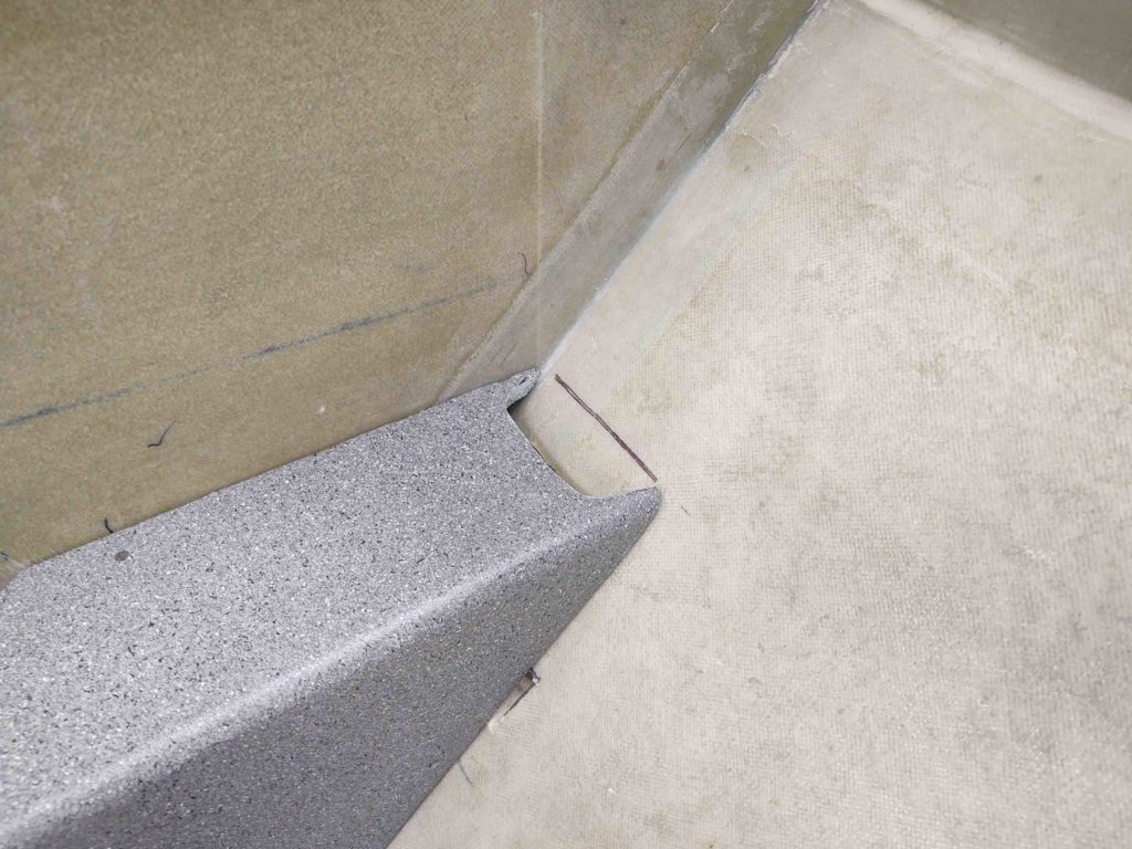
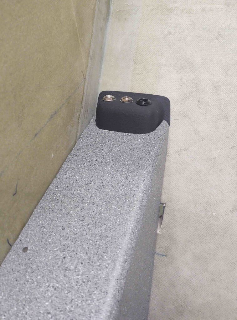
Here we have what she looks like in place.
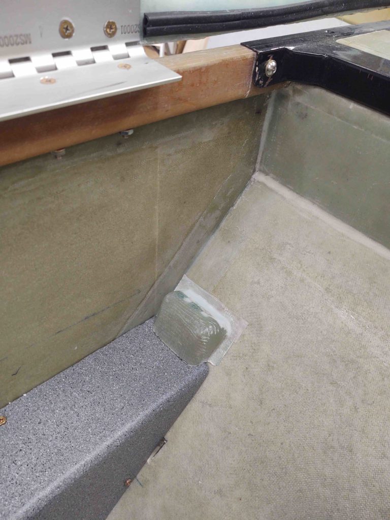
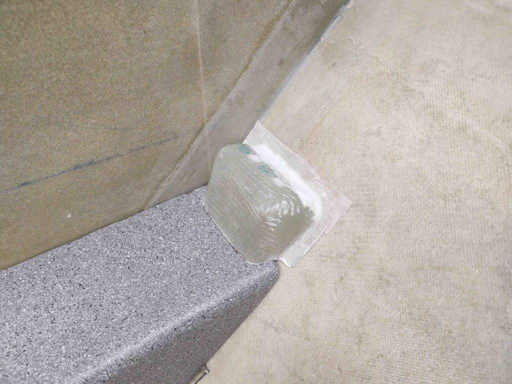
And an even closer shot. Now, the final look will have it actually sitting just a bit lower as I’ll most likely notch the back edge of the armrest to fit around the bottom edge of the PIC headset jack cover. Besides giving the PIC headset jack cover a bit lower profile, it will provide a path for the headset jack wires.
 Yet another shot.
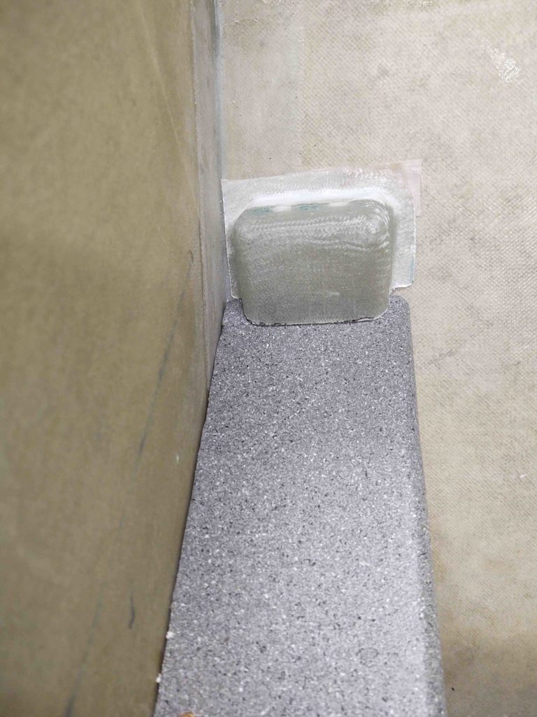
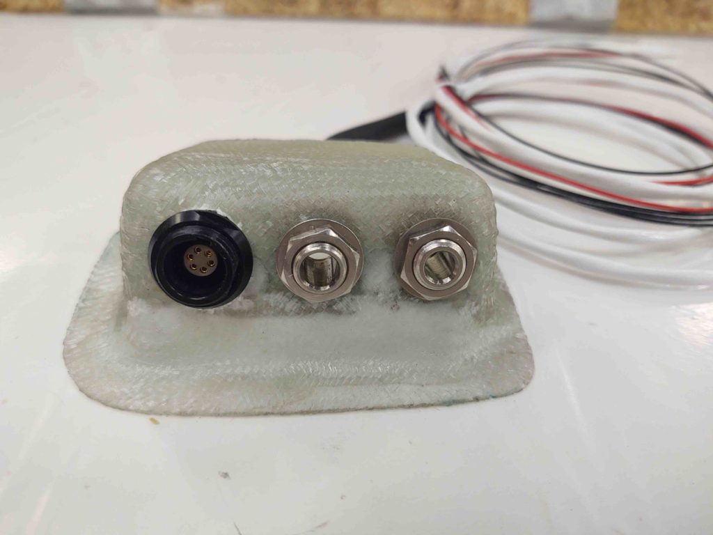
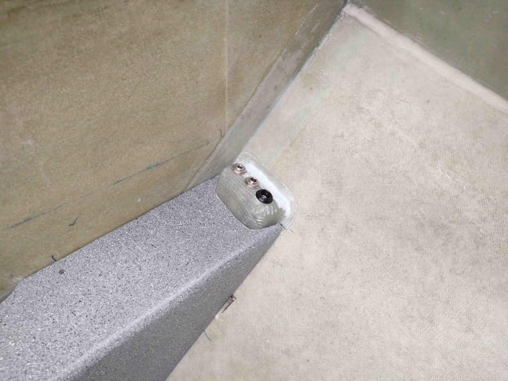
24 August 2020 — Today I drilled the holes for the traditional headset jack plugs and the Bose LEMO jack. Admittedly, since the LEMO jack has flats on the side I needed an oval hole… and I got a bit overzealous in my making the hole a bit oblong. So I’ll be filling in the slightly oversized hole with a bit of RTV, etc. My bad for rushing . . .
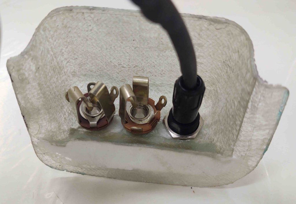
Here’s an inside look at the jacks.
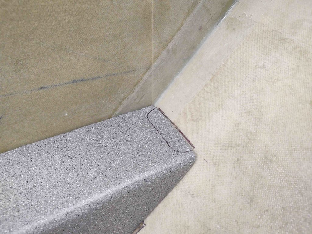
And the initial placement on the right armrest. My goal was to actually trim more off of this housing, which I did eventually with another 0.6″ off the open/bottom end.
Again, this its the initial cut line. I went through a half dozen iterations before ending up with my final configuration.
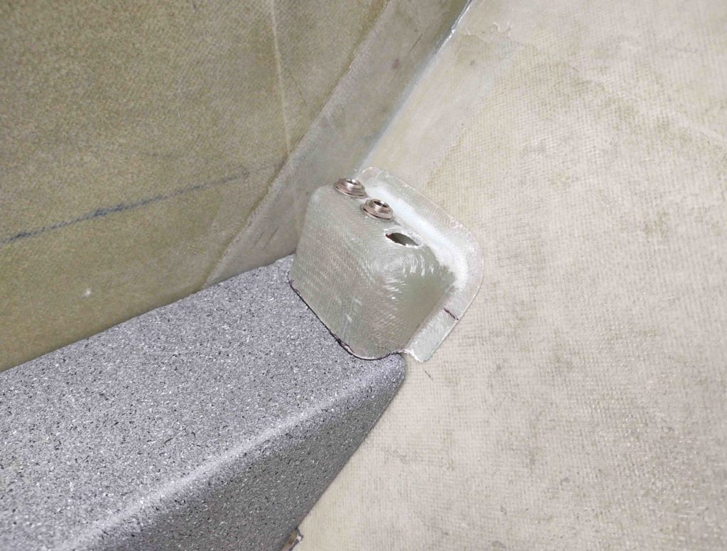
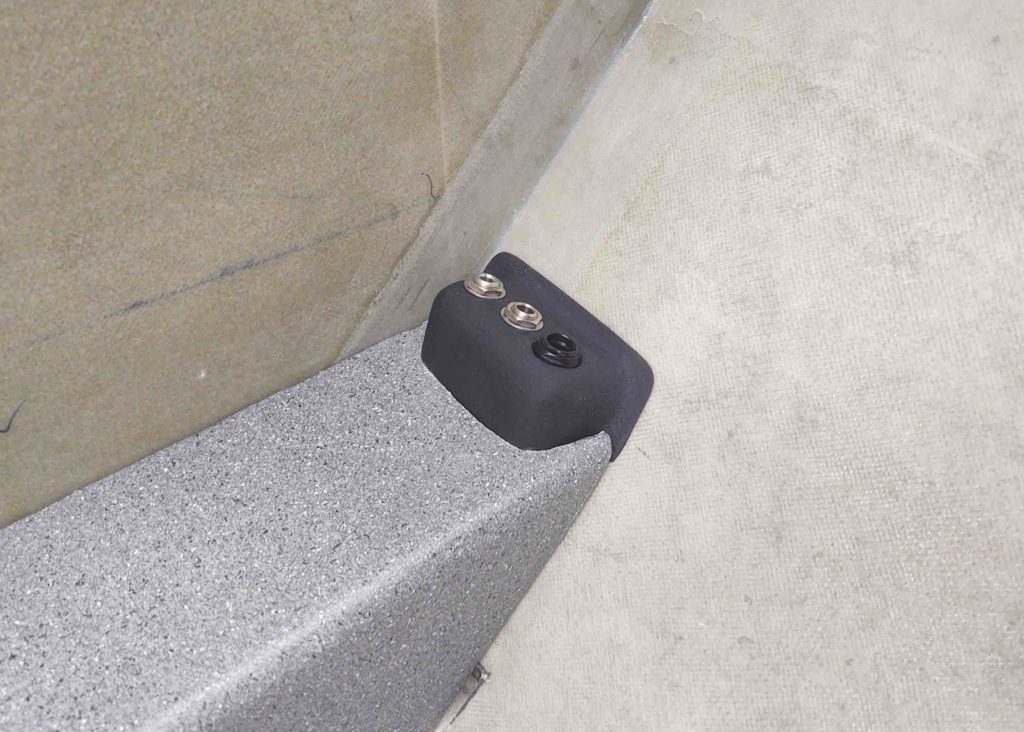
. . . which is this one.
Driving the headset jack cover further down into the aft armrest not only gives me a lower profile overall on the headset jack cover assembly, but with the angle of the cover it also allows me to remove the armrest with enough clearance around the headset jack cover to leave it in place.
Again, it also allowed me to remove a bit more material on the cover, albeit lightweight, for a skoach of weight savings.
•••
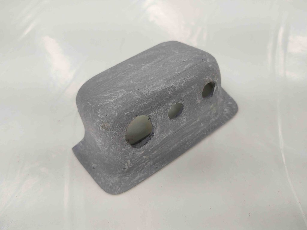
25 August 2020 — Today I worked more on the PIC headset jack cover.
Well, I wasn’t too concerned about this small module stuffed in the corner having a pristine finish, so I simply hit it with a couple of coats of gray primer.
Nope… too ugly. The weave wasn’t too bad, but there was some holes and scars that were a bit glaring. So I gave it well over 24 hours and then hit with some micro (yes, a bit backwards in the process I know).
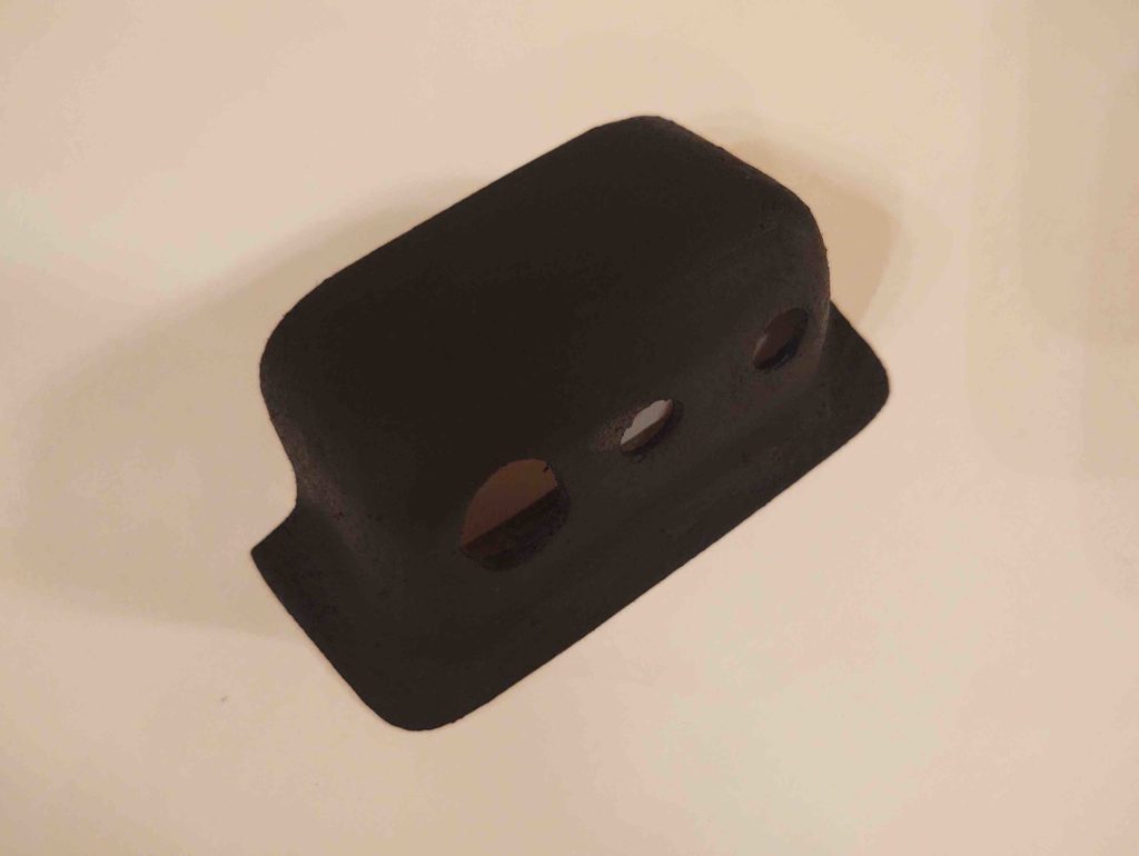
Then, just as with the D-deck upper face plate, I painted this guy black and baked it. Admittedly, I was curious to see how this composite piece would handle the heat.
Well, after about 45 min I noted that it had some off-gassing bubbles going on.
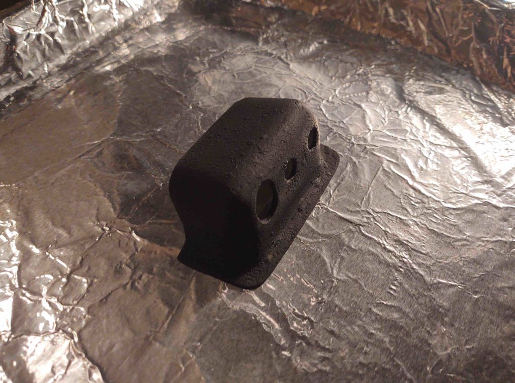
But interestingly enough, once removed from the heat for not even 2 minutes, the bubbles went away . . . looks fine!
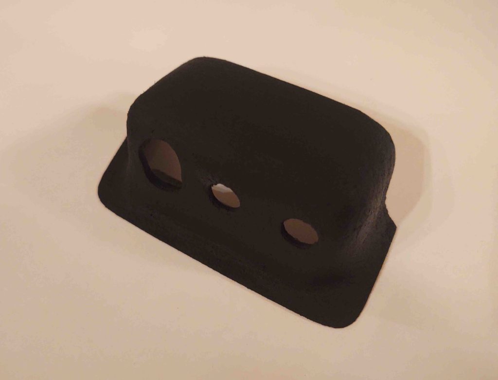
Here’s another shot.
Yep, this dawg will hunt!
•••
26 August 2020 — I got to work in the shop late afternoon. First order of business was to check out how the freshly painted PIC headset jack cover looked in place. Not too objectionable in my book!
•••