
Chapter 24 – Left Pilot’s Armrest Console
This page covers the building and installation of the left pilot’s armrest, with some associated throttle quadrant info also posted in Chapter 23. Also, there is a bit of overlap with the general armrest build discussion in Chapter 24.
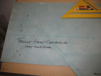
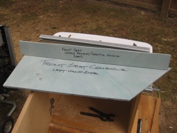
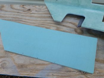
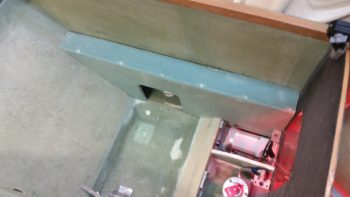
29 June 2013 — I measured out and marked the Left front console.
•••
30 June 2013 — I mocked up the sides of both front seat consoles.
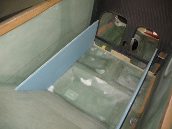
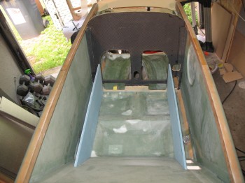
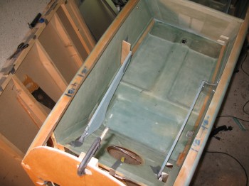
After I got the sides of the consoles fitting decently, I cut the tops and checked out how those fit. Grant it, I had to take into account that their sides are straight and the fuselage walls are curved, so the fit obviously wasn’t exactly like they will be when ready to install.
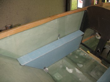
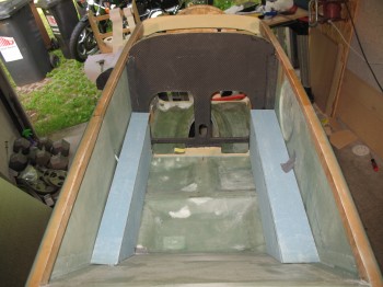
The front console sides are wedged in nice and tight, so mocking up the tops are no problem.
•••
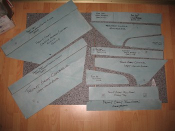
9 July 2013 — I gathered up all the individual parts of the Chapter 16 and 24 consoles, arm rests & front seat ribs for some pics, as shown below:
•••
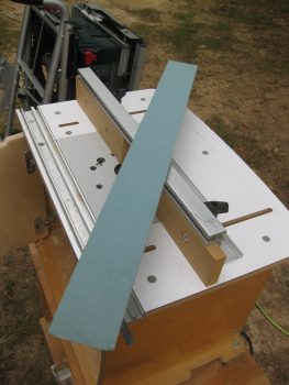
6 October 2016 — Today I unleashed the Big Dog . . . literally, my Big Dog router table from the outside shed. I went through the trouble of pulling this sucker out since there’s simply no way to get the radius I want on the top armrest pieces (and to match the pre-existing radiused edge) without using a router table.
I set up the router table to route a small scrap piece of 3/8″ foam that was probably from the same originally piece as my side consoles since it has a ply of glass on one side. I would have actually preferred to put the glassed side of this scrap piece on the inside of the left armrest and had fresh foam on the outside, but the way the scrap piece wass shaped I had to radius the side with the 1 ply of BID on it.
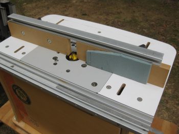
I then pulled the front left armrest pieces out and raidused the top piece of that.
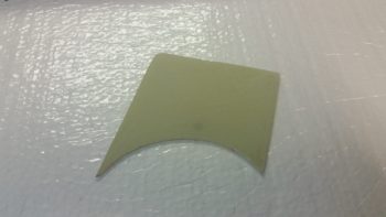
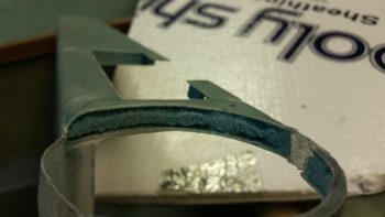
Here’s the long, narrow top piece of the front left armrest console.
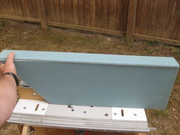
And here’s after I rounded over the edge.
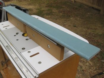
And a quick mock-up… looks good!
•••
18 May 2017 — [This is also posted in Chapter 16] Today I pulled out my router table to round over the edges of the lap seatbelt access port. I had planned on doing this, just as I rounded the bottom edges of both back seat armrests, but again Dave B. reminded me of it last week so I put it on the short task list. Now, the right armrest seatbelt access was good to go since I widened & squared it a bit last week. But the left armrest, which is still in individual pieces, I hadn’t touched since 2012 when I cut it out.
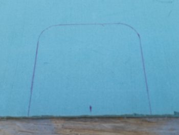
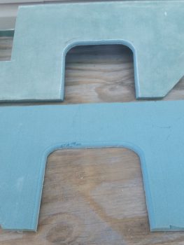
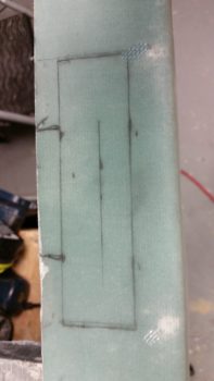
I verified & marked the spot of the left seatbelt bracket on the left armrest. Then I used the right armrest as a template to draw out the seatbelt access port.
I was now ready to cut this baby out!
Well, I tried to use a hole saw as I had with the right side. The same exact one in fact. But as soon as the saw blade touched the fiberglass on the back it came off its mount and went absolutely ballistic. It’s done this a few distinct times before, but usually just a minor ding before. No worries. I can assure that this will never happen again with this hole saw because it is no longer with us ( . . . a moment of silent please for the POS hole saw bit).
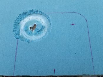
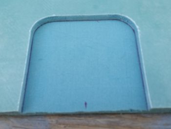
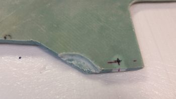
So, I backed up the aft line about a half inch, upped the top line by about a quarter inch, and cut this sucker out! Here’s the result below.
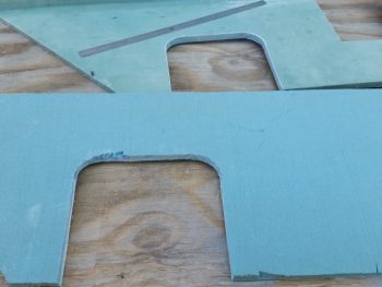
I then radiused both left & right armrests using my router table. As you can see, now just a little bit of extra micro will fill in that gouged foam EZ’ily.
•••
8 September 2017 — Today I performed an extensive assessment on the components that will get installed into the left PIC armrest. I played a bit of Tetris figuring out exactly how all the bits n pieces would fit. Specifically, I took a hard look at the oil heat and seat warmer wiring and components’ space requirements. This of course is all in prep so that I can start installing the left armrest console and internal components.
•••
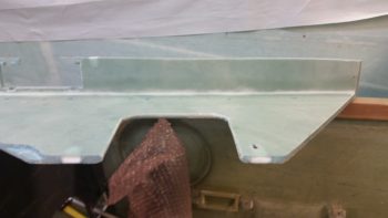
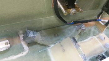
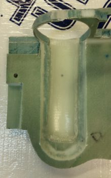
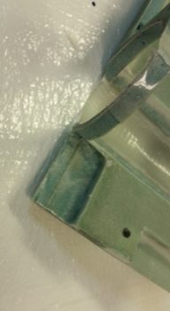
17 September 2017 — Today I notched the bottom center of the left pilot armrest with a triangular opening to allow the armrest wall to fit over the pilot thigh support wedge duct when installed. I also had to narrow the thickness of the wall on the outboard side of it that was adjacent to the air vent plenum duct in order for it to fit in its planned location.
•••
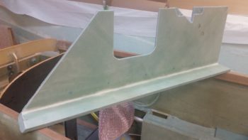
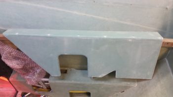
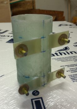
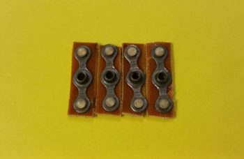
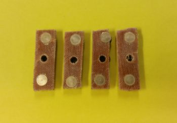
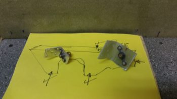
30 October 2017 — The weather was unexpectedly sunny & nice, so I took the opportunity to cut 4 beveled plywood hard points to reinforce the aluminum threaded inserts that the throttle quadrant will mount to. I then rounded the corners with my sanding block.
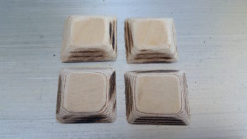
A bit later I drilled the appropriate size holes and then trimmed the top 2 plywood hard points… this throttle quadrant is marketed more towards RV bubbas so it mounts a bit odd going into a Long-EZ with the top mounting bolts almost even (but maybe 0.050″ low) with the top of the throttle quadrant plate. Not a huge issue, I just either had to trim down my top hard points or have to deal with them sticking above the top of the armrest.

To be clear, I had sat in the pilot’s for quite a while in an attempt to ascertain the right spot (for me) to mount the throttle quadrant. Since I’ll have to redo the actual lever for the throttle handle I have some flexibility on the height and left/right position of the handle, thus the main issue to determine today was forward/aft positioning and did I want it sunken a bit below the surface of the armrest or not [I chose not].
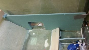
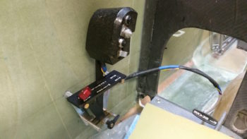
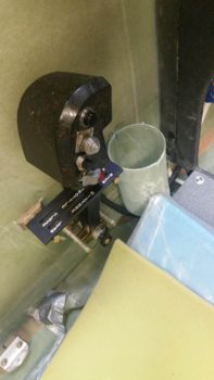
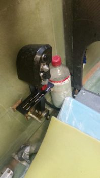
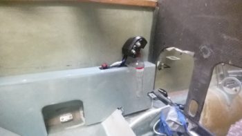
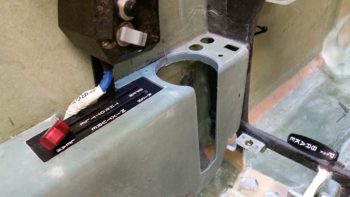
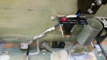
This pic below jumps ahead a bit after I had decided where I wanted the throttle quadrant mounted and subsequently after the holes in the left fuselage sidewall were drilled. I set the throttle quadrant threaded aluminum mounting posts into the holes, climbed in and ensured that this is where I wanted it before I finalized the install. I did move it forward 0.4″ from my originally planned mounting position. As you’ll note by the pics below, obviously I liked this spot so I pulled the pressed forward with the install.
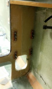
I prepped each threaded aluminum insert by taping up the outboard (open) ends of each one, and then bolting a tape-covered washer to the inboard open hole. I then mixed up some flox and started by floxing the threaded aluminum inserts into each plywood hardpoint. I then floxed the threaded insert/plywood hardpoint assemblies into their respective holes. Of course the back (outboard) side of each plywood hardpoint was slathered with flox as well, providing a fair amount of surface contact area for added strength.
[In hindsight, if I had really taken note on how close the bottom 2 hardpoints were together, I might have just made one longer plywood hardpoint. No worries though since what I used below worked fine too.]
While the floxed-in threaded insert/plywood hardpoint throttle quadrant mounting assemblies cured, I then prepped the layups by cutting and prepregging 2-plies of BID for each hardpoint.

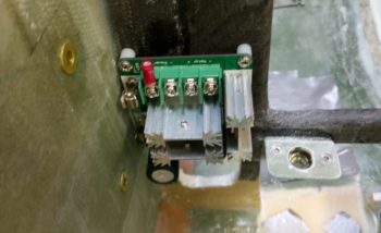
After the flox cured the majority of the way, I then mixed up some more epoxy, wet out the prepregged 2-ply BID layups and went to work. Here you can see all the threaded insert/plywood hard points glassed and peel plied. I then set a heat lamp on them (….my shop was a balmy 66° F).
It was getting late so I left the threaded insert & plywood hardpoint throttle quadrant mounting assemblies alone to cure in peace while I went upstairs to get a bit of research in.
•••
31 October 2017 — Today I started out by removing the peel ply from the cured throttle quadrant mounting hardpoint layups and then cleaned it all up. I then drilled the holes into each of the 4 hard points, removed the protective plastic wrap I had stuffed into each one to keep the nasty stuff out, and then cleaned up each hole to allow me to test mount the throttle quadrant.
I have to say it all looks good and I’m very pleased with the position of the throttle quadrant.

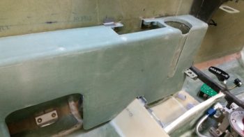
Today was more of an R&D day than it was a build day, as there was a lot of configuration stuff to figure out for not only the immediate throttle quadrant area, but the entire left armrest console. For example, when I placed the left armrest vertical wall in place, I immediately noticed that it “fanned” out in a way towards the aft end since the armrest wall was basically parallel with the centerline of the airplane. This makes the side wall look as if it’s fanning out too, because in reality, well, it is since the fuselage gets wider at the pilot seat bulkhead. This is probably even more pronounced on my plane since I have a more football shaped fuselage than do most Long-EZs.
I also needed to see how the seating space was affected in the pilot’s seat by this “fanned” out left armrest sidewall. Interestingly enough, I had plenty of room either way as I wasn’t really pressed against either one. I sat in the pilot’s seat a good 45 minutes simply taking notes and getting a good feel for how the ergonomics of possible configurations would work. I will add though that the past few days, being able to actually sit in the cockpit and process ideas based on real dimensional data, have been invaluable.
Before I could decide to kick the aft end of the left armrest vertical wall outboard or not, I needed to know if the aft end would still allow me to mount the fire extinguisher in it since I really don’t see anywhere else to mount it . . . and keep it accessible in case of emergency [Side note: I’ve seen so many canard aircraft with fire extinguishers that are truly only accessible on the ground… not good in my book!]
So I drug out the fire extinguisher and low and behold, if I kicked the aft end of the left armrest wall outboard about a 0.25″ (e.g. narrowing) it will still allow me to slide the fire extinguisher in there . . . with a caveat: I’ll have to glass the aft end of the left armrest vertical upright with the inside glass laying up glass-to-glass with the glass on the exterior of the armrest console. No big deal of course, just a bit more work.
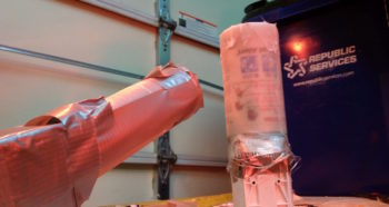
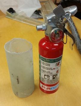
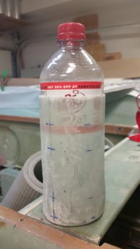
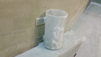
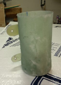
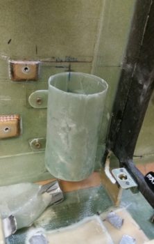
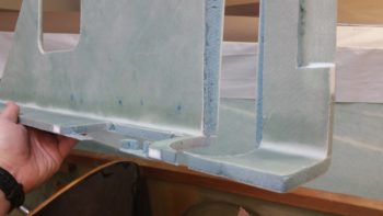
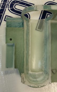
With data in hand, I decided to go with the narrower, albeit straight, armrest configuration. So I was about ready to glass the top and side of the left armrest together and then the ancillary stuff, but honestly the armrest was the easier layup so I went ahead and knocked out the more difficult ones first: the glass sleeve (tube) that the fire extinguisher will get mounted into (on the left, pic below) since I won’t be using the included metal bracket; and the cup holder that I plan on installing just forward of the throttle quadrant.
Interestingly, I needed the ID of the cupholder to be 2.9″ and the only thing I could find that could be used as a mold (without making one from foam) was a small household fire extinguisher that I pulled out of my other house when I sold it (shown on right, pic below).
A point of note on these: due to the fact that I have a TON of leftover UNI from previous layups, I used it for the majority of glass in these 2 layups.
•••
1 November 2017 — Today I started out by prepping the vertical wall and the narrow top piece of the left arm rest to micro & glass together. I glassed one side of these these pieces, along with my other armrests, back in the 2013 timeframe. I of course peel plied them and now it was time to remove the peel ply, which wasn’t too bad once I finally got a corner piece to grab ahold of.

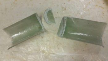
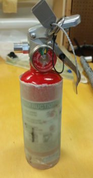
I’m going to digress a bit from the armrest –which is really a basic micro together and secure with 2-ply BID tape deal– to do discuss a dire situation: my cup holder! I have to tell you, I’m kicking myself for not grabbing a shot of the cured product before I pulled it off of its rather odd form: a kitchen fire extinguisher. But I was looking for a 2.9″ diameter form and that was the only thing I could find. Well, I didn’t follow protocol and take the time to tape up the very bottom with packing tape. I did grease it down with a light coat of WD-40, but apparently that didn’t hold up to hours of cooking under a heat lamp.
Thus, I paid for my sin with quite a hassle getting the last 1/4″ of the bottom off the form… and man was it stuck! As you can see I had to resort to slicing the layup in half all the way around. And I did NOT remove the bottom piece as you see in the pic below, it came off all on its own as a result of the brute force required to get these parts separated from the form.
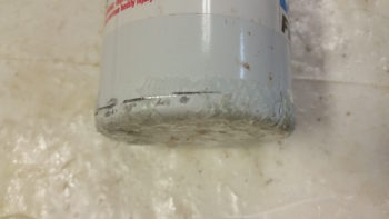
Here’s the bottom of the fire extinguisher, replete with remnants of glass painfully extracted from my poor cup holder. What’s a guy gotta do just to be able to have a cool beverage within reach while flying?!
Ok, so I micro’d and glassed the left side arm rest pieces together, and put it under the heat lamps. Then after the initial repair layup on my sad cup holder, I put it under the heat lamps as well.
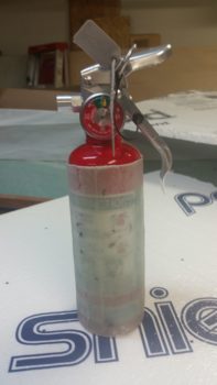
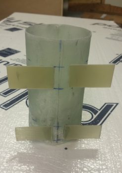
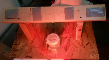
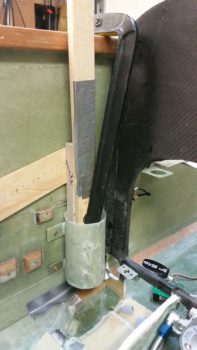
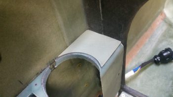
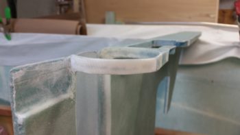
With my 2 layups curing under the heat lamps, I then got to work on the fire extinguisher. I don’t plan on having the fire extinguisher sitting so deeply in its fiberglass mount (as I glassed it so high up), it’s just that since the fire extinguisher will be mounted on the same angle as the pilot seat, I’ll have to cut the mounting tube at an angle to be flush with the top of the armrest (see mockup below). In short, I needed a longer mounting tube to allow for the mounting angle when I cut it.
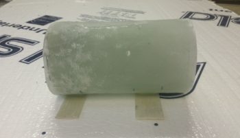
As you can see, this layup extraction from its form –the actual fire extinguisher– went much, much easier (thank goodness!).
Here’s a peek into the inside of the fire extinguisher mounting tube.
Cleaned up extinguisher and its mounting tube.
Ahh, nice tight fit!
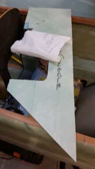
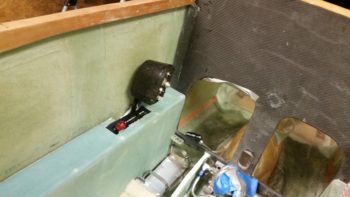
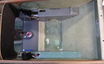
Here’s a basic idea where the fire extinguisher will get mounted. Once the strake baggage area is cut out, I’ll turn the extinguisher 90° so that the gauge is facing forward and the handle overhangs just inside the baggage compartment. This configuration may seem like it will get in the way of my elbow, but unless I push my arm back to a point that is uncomfortable, I won’t even feel it. In addition and as I noted earlier, most importantly I’ll be able to reach it IN FLIGHT.

This may seem like the same shot as before, but this is showing the seam the I had to cut on the fire extinguisher mounting tube to remove it from its “form” resealed together by a cured 1-ply layer of BID.
By this point my 2 pieces of the left armrest were now just the left armrest. I then pulled the peel ply and cleaned up the glass overhanging on each end.
I then spent a few hours (yeah, it doesn’t seem like it should take that long!) first building a glassing stand, mounting the left armrest to the stand and then actually glassing the external surface of the left armrest. Again, since I have a TON of spare UNI pieces I actually used 2 plies of UNI on this armrest vs the 1 ply of BID I used on the others to glass the top skin [Remember, since these armrests are now all removable, I’m not adding an extra layer of BID as per plans since the current structural strength is only for the armrest itself].
I wasn’t planning on peel plying the left armrest layup, but I accidentally poured way too much epoxy into the cup. So, ended peel plying the layup and also glassing another couple of open areas on the seams of my now much happier cup holder.

•••
2 November 2017 — I actually started off today pulling peel ply and doing a rough cleanup on left armrest layup. I did a bit more thorough trimming later on in the pics below.
Then I started in on my cupholder. I realize, without the plane being close to flying, that folks may wonder why I’m focusing on some things that seem rather insignificant in the grand scheme of things, especially in regards to getting this plane in the air. I have to say that is quite often the mantra I hear either online or from other builders in person: “Just get ‘er in the air, all that other stuff will come later!”
Well, if you’ve been reading this blog for any amount of time you’ll know that I respectfully disagree, because in my mind what we’re building here is a system. How often a $3 part is the one thing that keeps you from using a household appliance? So, if I am to finish the left side armrest, I must know how ALL the pieces are going to fit inside it… you can really see how every new area becomes a puzzle with the goal to make all the pieces fit.
Having heard stories and seeing firsthand what a pain is to keep a bottle of water at the ready for some hydration during a 3 hour trip, and not tucked away in a spot where although you can feel the nice cold bottle pressed against you, alas, you know that you’re not going to drink anything until that plane is on the ground. The bottom line is that Long-EZs are not Cessna 172s, and to get all the good out of them we must accept some of less than stellar characteristics of the design: as in NO space to put stuff.
Ok, off my soap box.
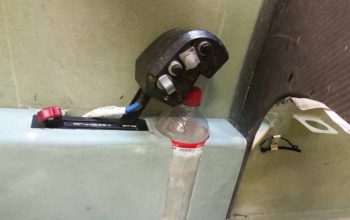
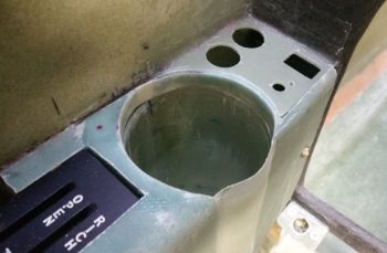
Here’s the cupholder with your typical soda bottle inside it. Water bottles are most often narrower than this.
The cupholder will sit immediately in front of the throttle quadrant, which is really the only place I could place this nearly full armrest height component given that the throttle quadrant must have clearance aft of it for the throttle and mixture cables to head rearward into the engine compartment.
However, immediately forward of the cup holder for a good 1.7″, resides all the electronics for the aircraft’s 2 PAX heating systems: 1) Oil heat system, 2) Seat warmers. These electronics include 3 individual relays, a PWM controller board and 4 switches (Oil heat/Seat warmer system select, PIC seat warmer OFF/ON, GIB seat warmer OFF/ON, PWM ON/speed control knob) on the surface of the very forward armrest at the base of the panel. In other words, a lot of stuff that could require some type of maintenance, troubleshooting, definite mounting, and possible replacement.
It was clear then after some thought that the cupholder must be made removable, versus my original plan of slathering it up with flox and merely sticking it to the sidewall.
I made up some mounting wings out of some spare glass I had (the same stuff I used for the fuel select valve bracket mounting screw cover) and some G10, and 5-min glued them on each side of the flattest part of the cupholder . . .
I of course did this while it was laying horizontally, like this:
Before doing a final glassing of these mounting wings, I checked out the mounting fit of the cupholder in conjunction with the already test mounted throttle quadrant. Since I dropped down the top mounting wings to clear the top forward throttle quadrant mounting reinforcement spacer, the cupholder looked like to integrate nicely.
I then whipped up some flocro, filled in the corner gaps between the cupholder body and the wings and glassed them with a ply of UNI and a top ply of BID. I also laid up 1 small piece of BID to cover the last remaining inch-long gap on the bottom corner of the cup holder. I peel plied all the layups and stuck the winged cupholder under the heat lamp.
BTW, that wood frame that the cupholder is surrounded by is the glassing stand I made for the left armrest.
Since I have so many pics in this post, I’m not covering my tasks chronologically, to keep from bouncing around topics with every new pic. Thus, a few hours later, here was the result of my glassing on the cupholder. I know it needs some cleaning up, a result of course of my initial screwup on not taping up the form! Ahh, unintended consequences. But although being ever so slightly heavier, and much uglier, it will still do the job… and of course, except of the top opening, will be hidden away out of site like Quasimodo.
I then got to work finalizing the edge cleanup on the left armrest layup.
I then did a minor sanding on the front & aft outboard edge to get the left armrest to fit in place initially. Although I still have a fair number of holes to punch into this thing, I have to tell you it was a great feeling knowing that my last armrest was glassed and that a task that I started over 4 years ago is finally complete!
•••
3 November 2017 — Today I spent quite a while determining the exact mounting location –specifically distance from the fuselage sidewall– of my throttle quadrant. With this throttle handle, I have to be careful in how I route the throttle handle cable to prevent chaffing or rubbing. I’ll be constructing a new, specifically designed throttle handle lever that will route the cable through the lever to ensure strain is minimized and keeps the cable from rubbing on the corner of the throttle quadrant plate.
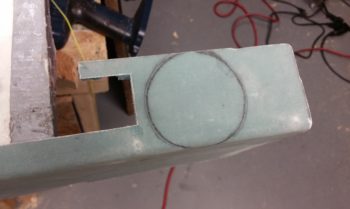
After marking off the area for the throttle quadrant on the top of the left armrest, I then cut the area out using my trusty jig saw.
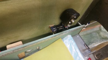
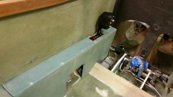
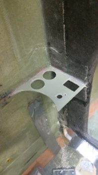
Below you can see the throttle quadrant mounted on the sidewall with the left armrest in place. You may note also that I made a bit of a blunder in my up/down placement of the throttle handle IF I wanted the top of the throttle quadrant plate even with the top surface of the left armrest, which I did.
Ions ago I had drawn a line across the fuselage sidewall where the armrest would be located. Unfortunately, this line was for the TOP of the armrest sidewall, but NOT the top of the armrest. Essentially, I had drawn the intersection line of the armrest sidewall and the armrest top. I kept this in mind when I mounted the throttle quadrant mounting hardpoints so the throttle quadrant base top was supposed to match the armrest top, but somewhere in the process I induced a slight mismatch. Currently the throttle quadrant base sits about halfway down in the top of the armrest. No big/uncorrectable deal, just another issue to work through.
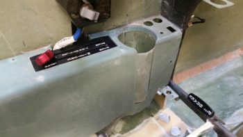
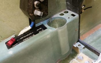
This shot shows a bit more of the armrest fitted into the fuselage.
•••
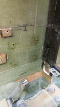
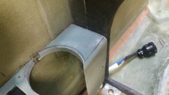
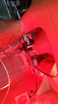
4 November 2017 — Today I started by drilling & prepping the 4 holes in the left fuselage sidewall for 4 RivNut hardpoints that will secure the cupholder to the sidewall.
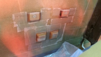
I floxed the 4 RivNuts into the sidewall to create these 4 mounting hardpoints to allow for a removable cup holder.
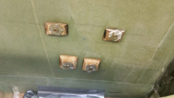
A few hours later here are the 4 floxed-in and cured RivNut hardpoints for the cupholder.
I then rounded the cupholder’s mounting wings into a pleasing shape… although a friendly fire incident occurred when my Fein saw kicked back hard and took a small bite out of the lower mounting wing. Minor fix, but annoying nonetheless.
I then test mounted the cupholder.
I then got to work cutting the cupholder access hole into the top of the left armrest.
Since the cupholder is a bit bigger in diameter than the armrest is wide, I needed a slot down the face of the armrest for the cupholder to peek out.
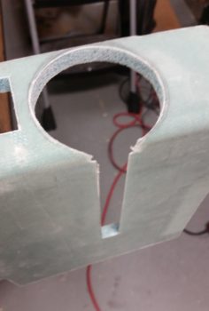
Here’s the left armrest in place over the cupholder after a few iterations of sanding and cutting away glass. It was almost midnight and my time for using the Fein saw was well past, so I called it good for the evening for any more work on the armrest.
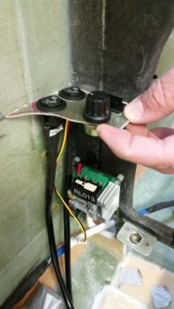
I then moved onto something a bit more quiet. Earlier in the day I decided on the mounting location for my PWM (pulse width modulator) board for controlling the oil heat pump. I drilled the 4 x 4-40 mounting holes into the front face of the lower instrument panel, left side under the armrest.
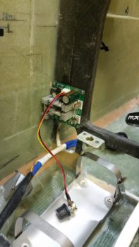
Now it was time to flox in the 4-40 nutplate assemblies to mount the PWM board, using the 4-40 nutplates that I ordered from Stein. Of course I had to make them first . . .
I then floxed in the 4 x 4-40 nutplate assemblies on the lower front side of the left instrument panel, with the PWM board mounted –with standoffs– on the aft side so as to ensure I got the correct screw alignment into the nutplate assemblies as they cured in place.
Here are the four 4-40 nutplate assemblies floxed in place on the lower left instrument panel for mounting the PWM board.
With that, I called it a night.
•••
5 November 2017 — A good majority of today was all about marking, removing armrest, trimming, sanding, installing armrest, fiddling, marking, removing, sanding, fiddling, repeat, etc. as I spent well over 2 hours dialing in the armrest to accept the cupholder. Of course I didn’t want to go too fast here, so patience was the key. Otherwise fitting the armrest in place around the cupholder would have been a cinch, but I would have had gaping holes at the interfaces.
I also realize this cupholder may stir up some controversy with some of the old guard or pilots viewing it, since it does sit near the front of throttle when in the WOT position. To be certain, I will take measures to safeguard against any inadvertent intrusion into throttle operations by a wayward bottle of soda/water. Not only will the sidewall be marked with “no riders above this height —– ” but I plan to have a little spring loaded swing out arm that not only tells me how tall ANY stowed drink in the cupholder can be, but also secure the container within the cupholder as I do wonderfully fun feats of aerobatics (within limits!) in my EZ.
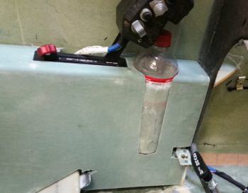
Here’s a closer view of the bottle/throttle interface and the bottom of the cupholder armrest notch. I will layup a couple plies of BID over the cupholder protrusion (taped so it isn’t part of the layup) overlapping onto each side of the notch so that that when it’s painted the armrest will have a nice smooth flow. More importantly, it will secure the very forward part of the armrest, which isn’t held on by much to the rest of the armrest. Btw, if you’re thinking this is a good recipe for pinching some fingers on the throttle, I tried a half dozen times and the bottle top comes nowhere my fingers — so no issue there.
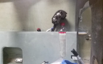
Here are a couple more wider angle shots showing more of the left armrest as well.
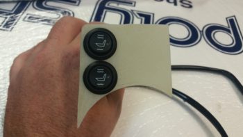
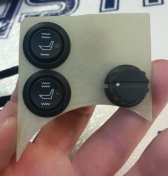
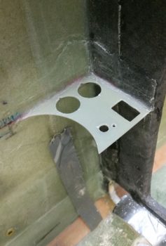
I then grabbed a piece of spare “trash” glass and used it as a template that was strong enough to actually keep switches mounted in place. Since this represents the heating switch mounting plate that will replace the front left corner of the left armrest (the armrest front corner foam & glass will get removed), I really only needed the actual shape for the top left side, the left edge, and left half of the cupholder access hole radius.
My primary goal was to see if I could somewhat comfortably get the 2 seat warmer switches stacked one above the other, which I determined I could. And the secondary goal was simply to fit the inboard switches in place… which as you can see I was able to do as well.
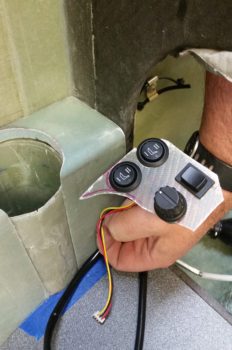
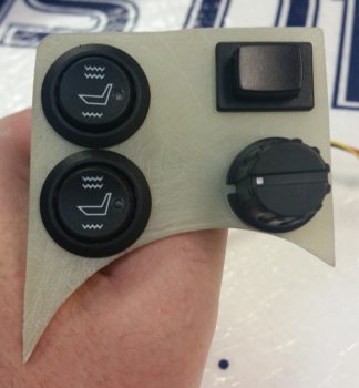
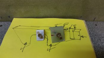
As for the heating switches, I of course stated the outboard switches are the front/PIC & aft/GIB respective seat warmer switches. The dial knob in the lower right is an OFF/speed control connected to the PWM board for control of the oil heat pump. Now, on the HIGH setting each seat warmer pulls about 4.4 amps, for a possible max total of 8.8 amps (On the LOW setting –where I plan to use them mostly– the draw is <1.5A each). The oil heat pump draws up to 7.5 amps. If I combine the totals of just my heating system output, I’m looking at over 16 amps… on a 40 amp alternator! Clearly I cannot allow this to happen, especially in flight. So the upper right button switch is a failsafe that allows me to only use one system at a time, either oil heat pump –OR– seat warmers, not both.
I then checked component installation clearance below the switch mounting plate to get an idea of what all I could fit between the switches and the mounted PWM board, since I had an idea to mount at least one of the automotive relays used to power the seat warmers. Since I need an armrest mounting bracket along the front edge of the armrest, mounted on the lower aft edge of the instrument panel (about where my first knuckle is on my index finger in the pic below), I determined there was simply not enough space for the relay… so it would have to go somewhere else [I had originally planned on mounting 2 relays for both front & aft seat warmers, but then settled for one… then none!].
I then diverged a bit from the wonderful bouts of seemingly endless sanding foam & fiberglass (and itchiness!) to knock out the wiring harness for the heating control system. As I noted above, the pushbutton switch allows me select one system or the other: oil heat OR seat warmers. To do this required me to interject a DPDT relay into the wiring scheme.
•••
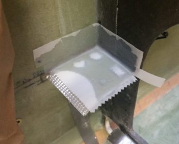
6 November 2017 — I started off today by digging out the foam in 5 spots on the edges of the left armrest to create divots, that once filled with flox would become mounting hardpoints. After digging out the foam, I whipped up some flox (actually flocro, heavy on the flox) with fast hardener, filled the divots with the flocro, then popped the armrest under the heat lamps and all was done in about an hour.
I’ll create some more mounting hardpoints in the left armrest in a few more spots, I just haven’t yet determined those hardpoint locations.
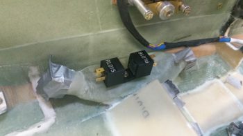
I had an idea last night where to place the Pilot & GIB seat warmer relays, but this morning I determined exactly where I wanted them and pulled the trigger on mounting a clickbond to mount the 2 relays back-to-back. I used 5-min glue to initially mount the clickbond, then about 20 minutes later I used flox to transition around the edges of the clickbond and laid up 2 plies of prepregged BID over top of it. I then peel plied it.
A couple of hours later I pulled the peel ply and test mounted the relays…. ah, good fit!
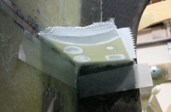
I then got to work on cutting the front left corner armrest heating switch panel out of G10. Somewhat analogous to the Dynon Intercom bracket on the right armrest, the heating switch panel will be a G10 plate that holds all the heating related switches and will become the front top surface of the left armrest. The current foam and glass of the existing armrest in that area underneath the G10 heating switch panel will get removed, all but a small ledge on the inboard side for alignment purposes.
Of course it took the usual multiple iterations of fitting, trimming, sanding and refitting to get the G10 heating switch panel’s shape dialed in, but I eventually got it. I then sanded both sides of the G10 plate for its eventually getting glassed into the fuselage.
Before setting the heating switch panel in place permanently with 5-glue and then floxing & glassing it into place, I made sure to remember to mark the outline of the plate onto the top forward surface of the armrest to identify the exact foam & glass area to be removed.
I then got to work pre-drilling the switch holes into the G10 plate. First were the 2 round 3/4″ holes that I widened slightly for the respective Pilot & GIB seat warmer switches.
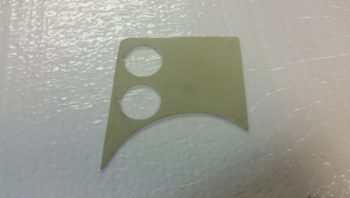
And here are the seat warmer switches installed in the G10 plate that will become the heating switch panel. (I realize that the seat symbol of the upper switch is “reclined” a bit more than the lower switch and will fix that before final switch install).
I then drilled and mounted the oil heat pump PWM control dial.
And finally the seat warmer/oil heat selector switch in the upper right hand corner.
I then removed the switches and 5-min glued the G10 plate in place in the front corner area of the left armrest. I then laid up 1 ply of BID on the top surface, overlapping onto the sidewall and instrument panel about an inch. I then peel plied the layup.
I had both epoxy and paint drying on different things, and not wanting to start another big task late at night I decided to rivet a couple of nutplates onto the last 2 existing/leftover brackets I have on-hand for installing the left armrest. I have other material as well, but I’ll have to make up some specific mounting brackets for the other 3 armrest hardpoints.
•••
7 November 2017 — I started off first thing this morning pulling the peel ply off the top heater switch panel layup and then razor cutting the glass. The plate looked good, and moreover it was really sturdy with it being glassed on 2 edges.
I set about immediately laying up another ply of glass on the bottom side of the heater switch panel and then peel plied it. I was going to use 2 plies of BID originally for the bottom side, but the plate felt really strong with just the top ply in place, so I figured just one more ply should do the trick in securing the switch plate.
Here’s a shot from above of the heater switch panel bottom side BID ply layup.
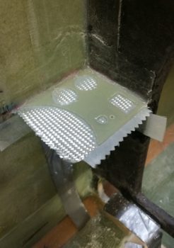
Concurrently, I also laid up a small ply of BID on the outboard edge of the top left armrest just behind the narrowest part of the armrest at the cupholder opening. I peel plied the inside of the layup in prep for glassing the inner ring of the opening at the top. I’ll eventually layup a ply of glass along each of the inner vertical sides of the cupholder opening as well, but for right now I’m more concerned about the top ring.
 I spent a bit of time cleaning up the final ply of BID on the heater switch panel (Yes, I realize it looks just like the pic above, but in the pic below it’s finished!). Since it was getting later in the evening, after I cooked dinner I took the rest of the night off and actually turned into bed at a much more decent hour than usual…
•••
8 November 2017 — It was getting late in the day today and I had yet to make the requisite amount of noise that I usually do in the shop, so I carefully cut out the front top of the left armrest that I had marked the outline of the heating switch panel onto. I then test fit the armrest in place over and around the now permanently installed heating switch panel, with of course then mandated rounds of sanding, fitting, etc.
I then mounted the cupholder and test fitted the left armrest in place again. It fits ok, but there is definitely some fine tuning required over the next day or so to get all these components dialed in and playing nicely with each other fit & finish-wise. Still, this gives you a good idea of the configuration on the front half of my left armrest.
•••
9 November 2017 — Today I spent well over an hour dialing in the left armrest, focusing on its fit & interface with both the heating switch panel and, yes, the cupholder. After getting the fit as close as I could, I decided that I needed to lock it into position by installing some mounting brackets –4 out of the 5 identified mounting bracket positions so far– to keep this thing from going all willy nilly on one end while I’m trying to do something on the other end.
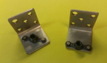
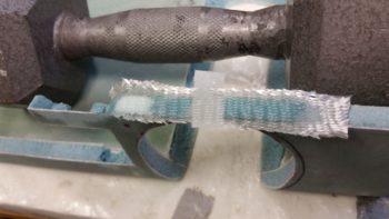
I cut a piece each of angled aluminum and 7-layer glass bracket stock for 2 more mounting brackets for the left armrest.
I then started making quite a bit less noise by simply using the drill to finalize the mounting brackets for the left armrest. I made up one bracket for a #10 screw, and the other a bit smaller for a #6 screw.
I then prepped the left armrest by taping up the edges in the immediate area of the mounting brackets, and then attaching the brackets in place.
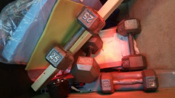
I then whipped up some flox using fast hardener and floxed the left armrest mounting brackets into place. Although just about each one needed some type of persuasion with a heavy dumbbell to keep it in place.
Also, to be clear, I have a few more mounting brackets I’ll need to install on the left armrest, this is just round #1. [BTW, the left armrest is at the very bottom of the pic, seat bulkhead is on right side]
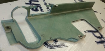
Here’s a shot of the wheel well cover (top left) and front side of the panel. I have the heat lamp shining primarily on the left armrest’s very forward mounting bracket that is attached to the aft side of the lower left instrument panel (lower right corner of pic).
•••
10 November 2017 — I started out today by pulling off the huge pile of weights that I had encased the left armrest with to keep all the mounting brackets aligned properly. I then unscrewed and removed the left armrest. I cleaned the protective tape off the edges of the armrest, then assessed the damage. I think the heat lamps made the flox flow a little a bit more than it would have in a low-to-mid-70 degree shop. Still, the 4 mounting brackets were on nice and secure, and that’s the main thing I cared about.
I was heading out to meet some from friends for lunch, so I quickly remounted the left armrest and then got to work laying up 2 plies of BID over the taped up part of the cupholder that was protruding out of the slot on the left armrest. I then peel plied it and set a heat lamp on it since the shop is a bit chilly.

About 5 hours later I returned home, pulled the peel ply off and cleaned up the layup. I was going to take another picture (uh, no joy) so there is no confusion on what I did, but what you’re looking at along the side of the left armrest is not the cupholder as before, but the new side of the armrest covering the cupholder. It just so happens that at the point of where the cupholder is located, the side of the armrest just happens to be 2 plies of BID thick. This layup not only serves to hide the ugly cupholder, but it greatly increases the strength of the very forward part of the left armrest. In addition, it will allow me a much easier time when it comes to painting this area.
I then prepped the front seat to climb into the fuselage. I would like to point out that the pic below is a bit historic for my build in that it’s the first time for my plane that the left & right armrests are bolted into place, and that the pilot’s seat thigh support is in place as well.
My last act of the evening, that took just shy of a couple hours, was to cut and remove the foam adjacent to the inside glass to created micro corners in the cupholder ‘U’-shaped area on the inside of the left armrest. I also shaped a micro corner in the aft side foam of the small flat area at the very front of the armrest (left in the pic below). After applying the appropriate micro, I then laid up 1 ply of BID at the front flat edge of the armrest, and along each side of the cupholder ‘U’ overlapping onto a ply of BID at the very bottom of the cupholder ‘U’. I then peel plied the layups and set the heat lamps up to help them cure.
•••
11 November 2017 — Today was one of those days where I didn’t seem to get a lot actually done, but I got a lot of stuff figured out . . . which is also important.
I started off by pulling the peel ply from last night’s layup, razor trimming the layups and then cleaned them up. I have to say they all came up pretty good. Since I added glass to an area that I had been trimming a lot for clearance, I then test fitted it to ensure I still had the proper clearance. It was a little tighter, but it still fit fine. I think if I sand it down well it should fit very nicely.
•••
12 November 2017 — Today I got to work doing some small layups. On the very front, top, interior corner of the left armrest, I micro’d the foam, created thicker-micro’d edges and glassed in a ply of BID. I peel plied this layup.
I also did pretty much the same thing for the heat/air duct plenum clearing notch I made in the inside of the left armrest at the bottom center of it. I did not peel ply this layup though (although when I cleaned it up after it cured it ripped some fibers loose on the edge, so maybe I SHOULD have peel plied it!).
•••
13 November 2017 — Today I had the goal of getting the inside & outside of the top armrest cupholder ring glassed.
I started off by creating some mini-trenches at the top & bottom edges of the inside armrest foam where it meets the top and bottom glass. I only really did this on the aft side of the cupholder ring since this foam has some mass to it. The front side of the ring is just a narrow fragile piece of foam with a bit of glass on the top & bottom surfaces.
A bit later you can see that I had successfully glassed a ply of BID on the inside of the left armrest’s cupholder opening ring.
Once the internal armrest cupholder ring had cured, I glassed the front external side of the ring with 1 ply of BID where it mates with the heating switch panel. In addition, I peel plied both of these layups.
•••