
Chapter 3 – Tooling Up: Machining
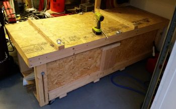
14 May 2018 — I had noted yesterday that my TIG welder was the “Elephant” in the middle of my shop, when in fact a truer statement would be that the fuselage dolly, having served its purpose well, is now the true elephant in the shop. Not only do I need to trim it down for space, but I need to repurpose it as a portable tool work bench for my upcoming focus on making some bric-a-brac for the plane.
I started by clearing off the top of the fuselage dolly and then giving it a good cleaning.
I then removed all the hardware and wood brackets off the top.
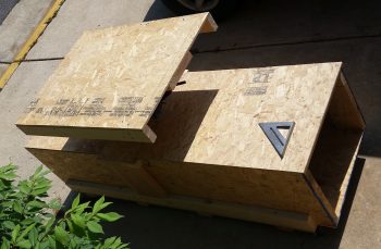
Here’s the last official pic of the fuselage dolly before it got a massive makeover (key some dramatic music from some crazy reality TV show!).

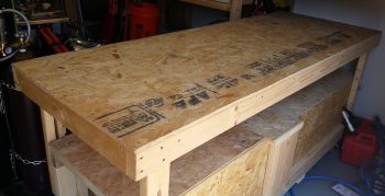
I determined yesterday that I need the top to be 38″ long, while the width will remain a hair over 30″. After determining the top area that would remain, I started on each end, cut and then removed the top shelf pieces and the underlying support frames.
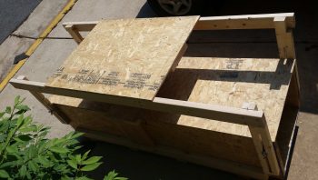
I then removed the 4 corner slide posts that would get reattached, and then trimmed the remaining overhanging wood support rails from the table top.
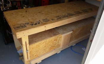
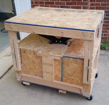
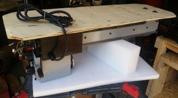
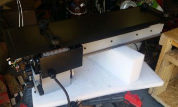
About 2 hours later I ended up with a much shorter version of the fuselage dolly that again, will now be used as a portable work bench that power tools will get mounted to.
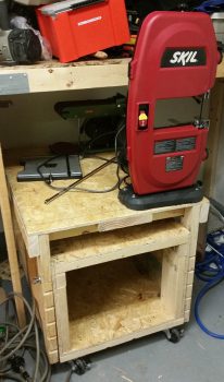
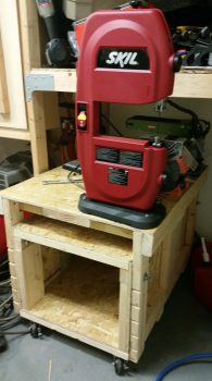
I mounted 2 recent acquisitions –the red 9″ Skil band saw and the Harbor Freight bench top combo sanding belt and disc machine– along with my ever faithful bench top grinder that has never really had a home. Yes, I know that these tools don’t get high marks for being the best in their respective classes, and I’m sure they got beat up a lot in tool high school, but by all accounts they work well enough to do what I’ll need them to and moreover, they were cheap (like me!).
You may have noted there is a spot on the opposite side of the table, which is for a mystery tool that for now we’ll call: Tool X. It is vitally important that the information as to the type and purpose of this tool not be made public at this time…. especially to Marco! haha!
•••
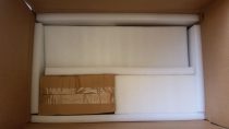
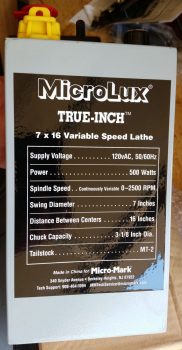
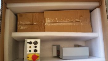
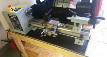
15 May 2018 —Today the UPS guy showed up with my lathe! Which, with the weight of it, conveniently came in 2 separate boxes.

Yep! It’s a lathe!

Two big benefits of getting this specific lathe was that A) it was actually in stock, and B) the reports on it NOT being delivered in a mangled, unrecognizable container were non-existent. In fact, the feedback was that it was packed VERY well for shipping (Two boxes vs just one greatly verified that fact).
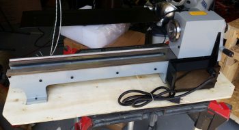
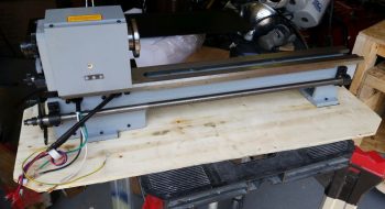
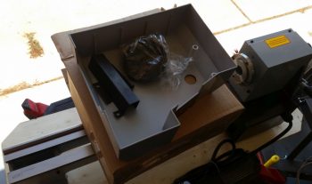
Box #1 contained the main body: the headstock and the bed (aka rails). It also contained the chip pan.
I then pulled the rather heavy headstock and bed assembly out of box #1, still mounted to its wood shipping mount plate.
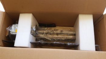
I then opened up Box #2. Words can’t express how pleased I was with the packing quality of these components. The foam here was not cheap styrofoam, and the overpacking was just off the charts.

Box #1 of Box #2 was the gear cover that mounts to the left end of the lathe to cover all the gearing on that end. Now, the motor is a direct belt drive configuration, but the ancillary lead screw drive and threading is gear driven.
Here’s the outside of the left end gear cover.
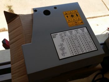
Box #2 of Box #2 was the electronics box.
The outside of the electronics box is the front of the lathe and the top is the control panel.
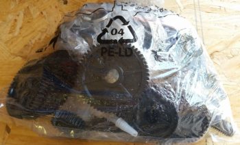
Then there was the odd components: the rubber mounting feet brackets and bag of accessories.
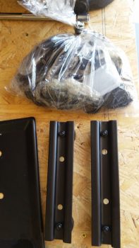
A closeup of all the threading gears in the bag of accessories. This bag also included all the hardware and handles.
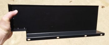
The rear back splash was honestly the only “free’ floating component packed in Box #2.
With all that stuff that came out, and there was still 2 boxes left to go in Box #2.
And again, the overpacking and protection was spot on!


One of the boxes contained the Compound slide with the old style tool holder attached (this will get swapped out for a quick change tool holder).
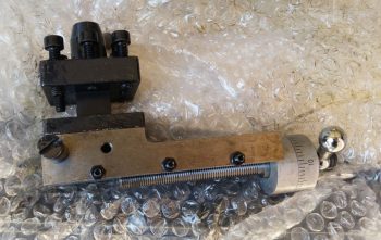
The top view of the Compound assembly.
Here’s the cross-slide assembly underside.
And the top side of the cross-slide assembly.
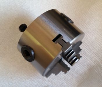
And let’s not forget the 3″ chuck (that I’ll most likely never use).
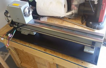
Here we have the headstock, the bed, the tailstock, the compound and cross slide. I should note that as all these metal parts were unboxed I cleaned them with solvent.
I then flipped the headstock and bed upside down to remove the wood shipping mount plate.
And then mounted the chip bed and feet assemblies.
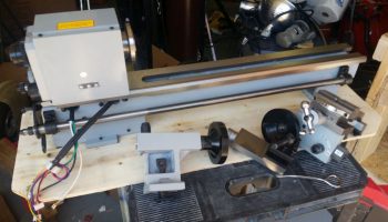
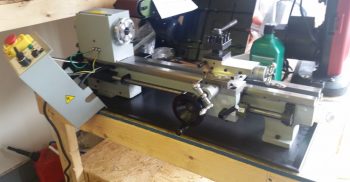
I then set the lathe assembly in place on the work bench.
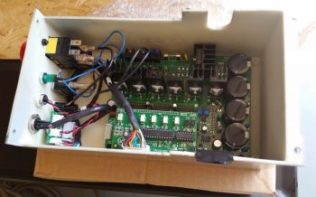
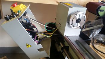
And started wiring up the electronics box.
A closer shot of the electrical wiring getting connected out of the electronics box.
As I was checking the operations manual I ran across a template with the dimensions spelled out to hard mount the lathe to the bench. I liked this idea much better so I removed the rubber feet and spent well over an hour (my issues, not the machine’s) getting it mounted to the bench. In the end, I like this configuration MUCH better… a lot more stable.
To see the lathe in action and overview of my latest tooling up, I created a fairly short video:
•••
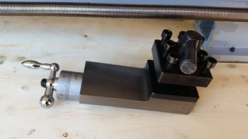
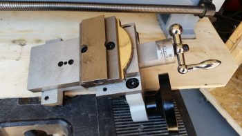
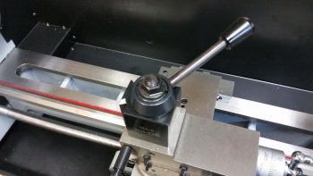
22 May 2018 — Today I received a digital tachometer and project box (to mount it in) from Ebay for the lathe. Since I had to make a Home Depot/Lowe’s run I decided to do a quick check of the upcoming tach install to ensure I had all the components I would need on hand…. which I didn’t so I ginned up a list. While I was at it I spent another 20 minutes mounting the lathe Quick Change Tool Post (QCTP) onto the lathe compound/cross slide/carriage.
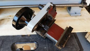
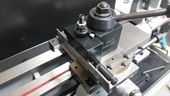
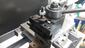
Once the heights of the various lathe turning/cutting tools are dialed in, the QCTP will allow me to swap out tools in literally seconds vs tens of minutes. Below are examples of a parting (“cut-off”) tool [top] and a turning tool [bottom], each in their respective tool holder [the attached tools are from a cheaper carbide tipped “indexable” tool kit I picked up from Harbor Freight, since it had good reviews…. I’ll use these tools as part of my kit starting out so if/when I break them during initial lathe ops, my cost of learning will be cheaper!].
•••