
Cowling Test Fittings during “The Grand Mock-Up” & Beyond
(Plus various other cowling fittings throughout the build)
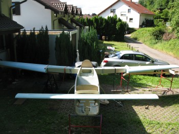
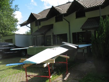
22 June 2013 — Today I pulled out all the stops . . . or should I say I pulled out all the pieces of the build so far. Before I am separated from my project while I spend a year in the Middle East for Uncle Sam, I wanted to get an idea of what this thing looks like put all together.
So I pulled the fuselage out into the front yard, and kept it covered while I collected the other components. Next up was the Centersection Spar which I placed into the fuselage for the first time since I completed it about 8 months ago.
After I got the CS spar & firewall in place, I added both of the wings next. Also, as you can see I had to throw on at least one winglet just to get an idea of how it would look. Although it was a little awkward to get it on the end of the wing so it looked half-way normal, I think I got in the ballpark. Well, and of course we can’t forget the canard… yes, it’s on there too!
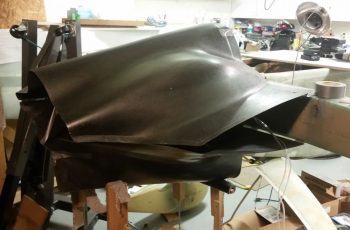
Once I got the wings on, it was now time to fill in what gaps I could to make it look at least a little like it had some mass to it. Next came the engine cowlings.
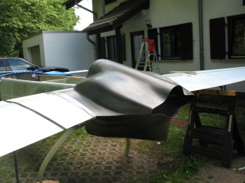
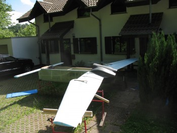
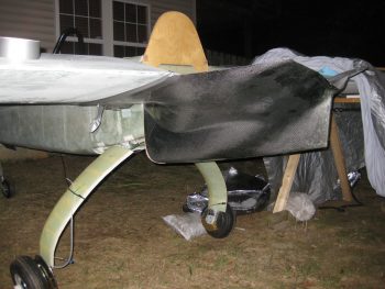
In the next couple of shots you can see how the lower cowling hangs down 4 inches below the stock/plans firewall. Again, since Mike Melvill had built a NACA inlet for his engine air intake the back end of his fuselage–and subsequently the firewall–was 4 inches lower than plans [in essence making the bottom line of the fuselage continue straight until aft of the firewall].
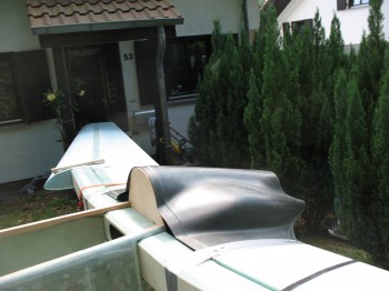
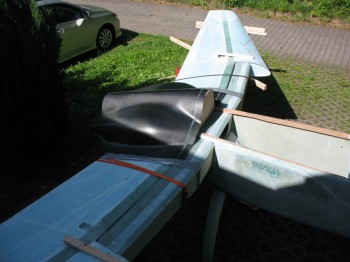
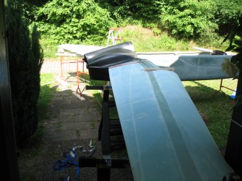
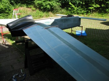
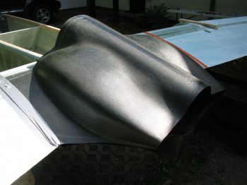
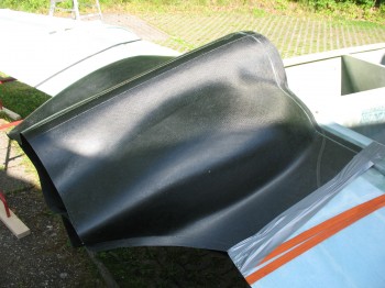
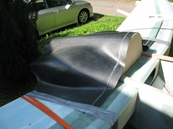
And then the following pics are more close-up shots of the upper cowling.
•••
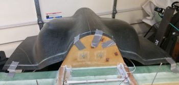
21 September 2016 — Tonight I finally got that lower cowling mounted so that I could mark up the firewall for trim.
I had to lean way over into the cowling in order to mark the lower line without disturbing the taped-in-place cowling.
I took this shot just to get an idea of what the bottom profile of the plane will look like.
Another thing that I did that is not shown in these pics is I ran a line from one wing TE corner to the other. This let me measure from the back face of the spar to the string to determine the sweep. I determined that I’m only 0.1″ short at the BL23 mark at the very inboard wing, and 0.4″ short on my wings’ sweep over the entire wing span: BL175.6 vs the plans BL 176. Again, not bad and I’ll take it!
•••
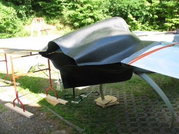
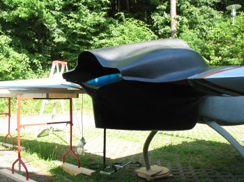
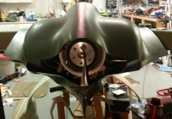
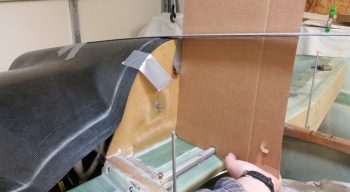
18 April 2018 — My goal today was to mock up the lower cowling in its close to final position (as best possible) to check the clearance between it and the engine air induction system… specifically the fuel injection servo. To better ascertain the position of the lower cowling, I went ahead and set the top cowling in place, which I was going to do in short order anyway.
I then used duck tape to help wrangle the 2 cowling halves into some semblance of order. I’m definitely happy with the fit of the cowlings, and although Mike Melvill had an IO-360 inside of them, trust me, they are still a close fit to an IO-320 sized engine.
I taped the cowling at the top cowling-firewall interface, and was glad to confirm I have a good firewall fit, with the shape of it matching the cowling shape.
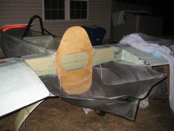
Since I had the top cowling close to its final position (I double-checked the plans, my notes, other builders’, etc. to ensure I had it close to where it needed to be…) I then made some templates to use for the cowling angle interface with the canopy and D-deck/ turtledeck assembly.
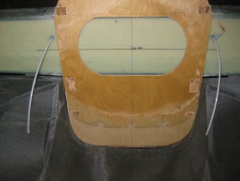
Here’s another view of my canopy-top cowling interface angle template. Clearly there may need to be a curve thrown into the mix as I mount the canopy, but it gave me a good starting point.
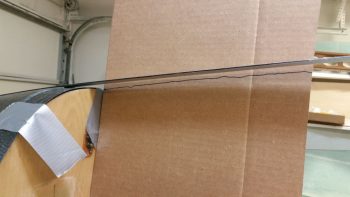
I also drew hash lines on the longerons and marked the extended angle of the top cowling contour about 18″ forward of the firewall.
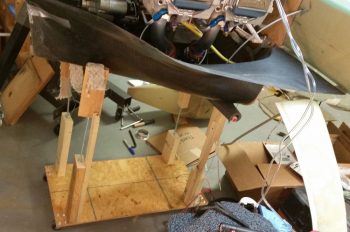
Here was my version of the lower cowling dolly. Mine needed to be much wider front to back and much taller than the one that Walter built for his airplane.
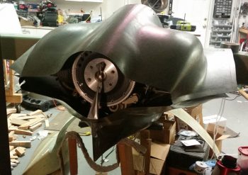
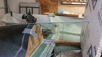
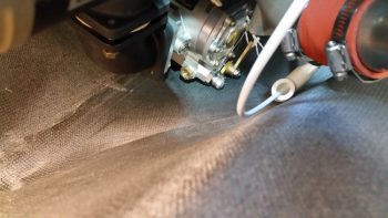
As you can see, I removed the top cowling to better check the clearance between the bottom cowling floor and the fuel injection servo.
Here was the best shot I could get of the fuel injection servo position inside the lower cowling. It may be hard to tell, but in this configuration there was NO clearance and the cowling is actually just touching the fuel injection servo. In fact, the very bottom nub sticking out to the right on the servo is the main fuel feed line attach fitting… clearly no room even to connect the fuel feed hose (see Engine Installation page for the rest of the story!)
•••