Chapter 23 – Engine Electronics
This page will cover the following electrical components found on, around or connected to the engine:
- ElectroAir Electronic Ignition System (including MAP sensor)
- P-Mag Electronic Ignition System (including MAP connection)
- GRT EIS4000 Engine Information System
- GRT MAP sensor
- B&C Starter (including starter contactor in nose battery compartment)
(NOTE: Except for actual installation details, the B&C Primary & Back-up Alternators will be covered in Chapter 22 – Electrical System)
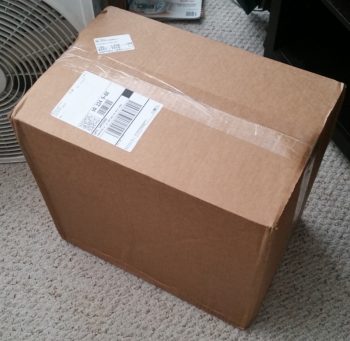
11 September 2017 — I didn’t get ANY actual building done on the plane today! Why? Well today I got a nice delivery from the UPS bubbas . . . you gotta love people who bring you airplane parts!
Hmmm? . . . a big box from GRT Avionics. This can’t be anything but good!
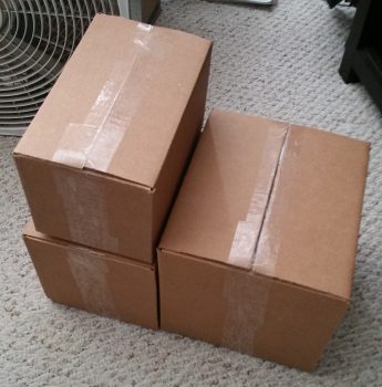
And what do we have here, 3 smaller boxes inside the big box.
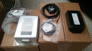
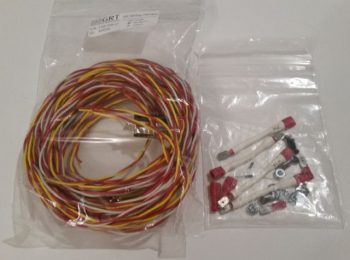
Small box #1 revealed HXr EFIS accessories: GADAHRS, magnetometer, GPS antenna puck, OAT probe, and wiring harnesses.
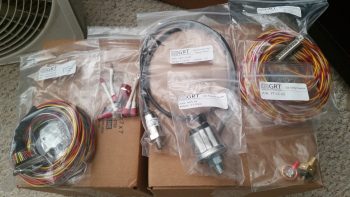
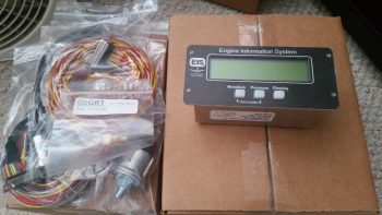
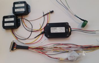
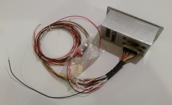
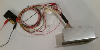
I then opened up box #3, which contained all the wiring harnesses and engine sensors for the GRT EIS4000 Engine Information (management) System. Since I needed a different MAP sensor that doesn’t come in any of the EIS4000 packages, I ended up getting the basic package and then just adding a couple higher quality sensors to the lineup.
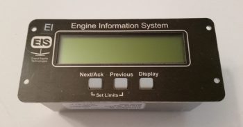
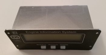
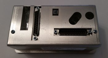
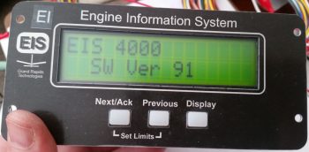
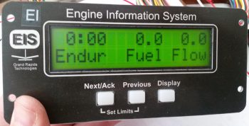
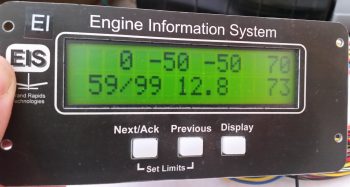
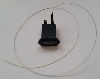
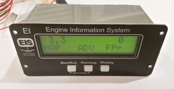
And here’s the very capable EIS4000 control unit. A lot of builders simply place this in their panel and call it a day, and it will work well that way. But to spice things up a bit all you need is one little 22 AWG wire to port all that info via serial data into the HXr & Mini-X and you can see all the engine data in beautiful, colorful graphical representation.
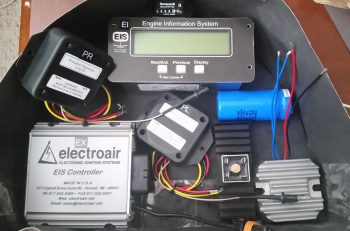
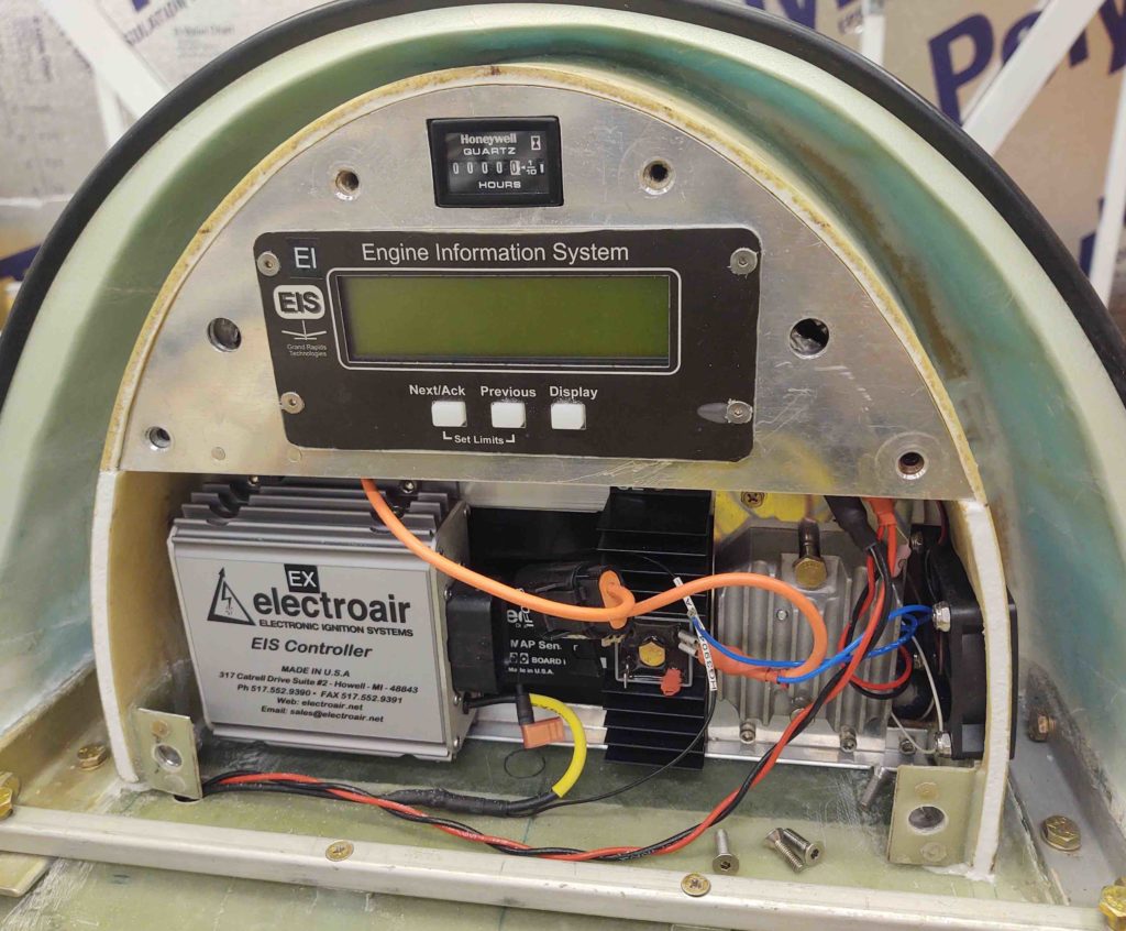
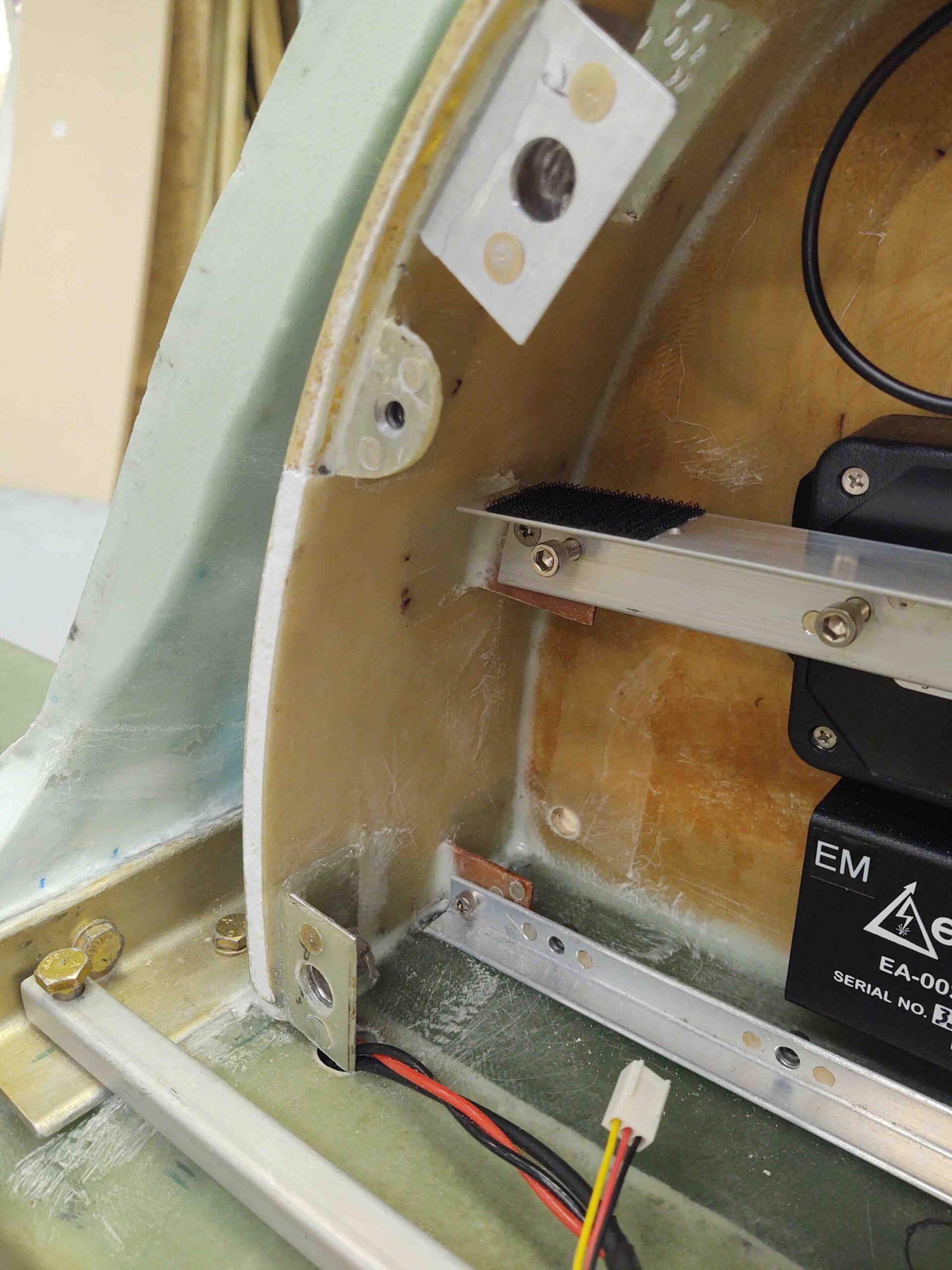
I can’t even begin to relay how many phone calls that I fielded today. So besides inventorying the new orders and crosschecking interfaces with components I already have on hand, I finished out the evening by “simply” figuring out the configuration of my GIB headrest (aka “component storage facility”) which will house the following (top down, CW):
- Hobbs Meter
- EIS4000 Control Unit
- B&C SD-8 Backup Alternator Capacitor
- B&C SD-8 Backup Alternator Voltage Regulator
- B&C SD-8 Backup Alternator Self-Excitation Bridge Rectifier
- Princeton fuel level control unit – Left Tank
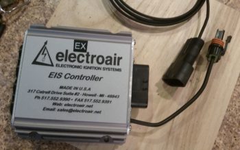
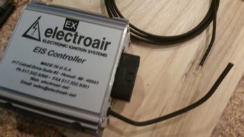
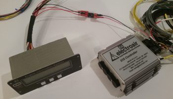
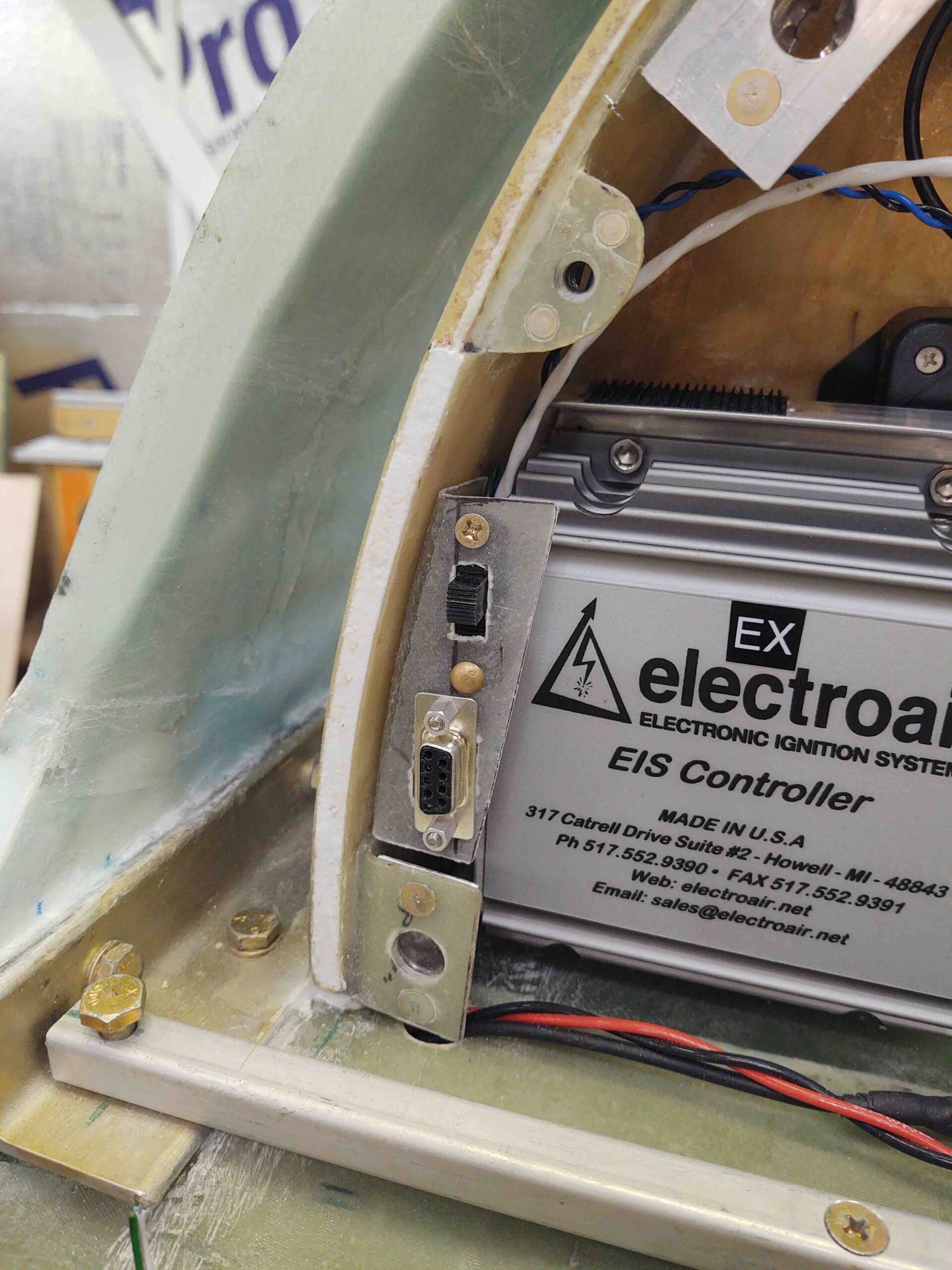
- ElectroAir EIS (Electronic Ignition System) Controller
- Princeton fuel level control unit – Right Tank
(That’s all . . . at least for NOW!)
•••
12 September 2017 — Today I had a myriad of personal things to take care of early on. When I got back to the build I really wanted to figure out some issues that I had run across when loading up the GIB headrest with components.
I had some questions for ElectroAir on their Electronic Ignition, and when I tried to call they were already closed. When I checked out their site’s FAQ section, I noted their new requirement for mounting the MAP sensor: they now want it mounted on the cold side of the firewall, where before they stated to mount it on the hot side. This new placement is in line with how GRT states their MAP sensor should be mounted, but throws a wrench in the works as far as how I have my MAP system configured…. so back to the drawing board. Literally.
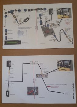
I didn’t want to just write a note and deal with this later, since the information I was collecting was all right in front of me. I spent a few hours researching configuration options, figuring out fittings, and the physical install on each side of the firewall. The end result was a couple of respective orders for very specific fittings (restrictor & barb), and an entirely new look of my MAP system by the time I was done. In fact, below is a shot showing my MAP system about a year ago (top) and what it looks like now (bottom diagram).
In addition, although I don’t have a pic for this, I also spent a good hour updating my firewall components and pass-thru diagram, which has changed significantly from a year ago as well.
•••
13 September 2017 — I started out today having a discussion with Mike from ElectroAir. I had a few questions on the installation of the ElectroAir electronic ignition system, most being just crosschecks on what I was planning on doing and that I wasn’t going to screw anything up doing it!
There are a couple of connectors on their EIS (not GRT) Controller harness that I inquired about: the first connector –that I want gone– are on the wires running to the coils, and the second just a connector inexplicably (to me) placed on the controller’s ground wire. The first will get replaced after I run the wires through the firewall to the coil, the latter connector will get removed altogether. Both with the blessing of ElectroAir.
All this really relates to wire runs both in the hellhole and through the firewall. That, in turn, relates to space required for wiring transiting holes through the firewall in the D-Deck / Turtle Deck / GIB headrest.
I then moved the ElectroAir MAP sensor from the engine compartment into the Hell Hole, by reworking a number of my electrical diagrams.
•••
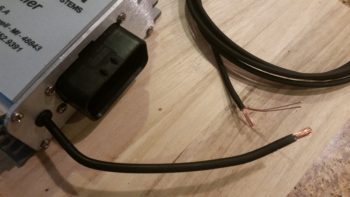
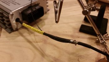
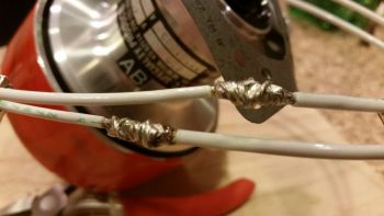
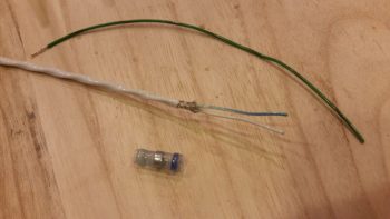
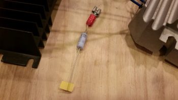
18 October 2017 — Today, while I had the soldering iron fired up & soldering kit ready to go, I knocked out a quick soldering task that I had open on the books: I ridded myself of a big, bulky, heavy and unnecessary deutsch connector that resided on the ground wire to my ElectroAir EIS Controller. To be clear, in my latest phone call with the ElectroAir bubbas, I specifically asked if this would present any issue: obviously they stated no, the connector was simply in place for ease of installation. In my case, it would not make installation easier . . .
So, I unceremoniously lopped off each side of the deutsch connector.
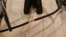
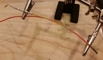
I stripped the wires and prepped them for splicing (notice the longer 3-strand “tail” on the top wire).
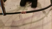
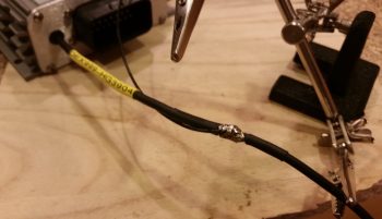
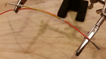
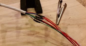
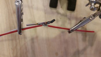
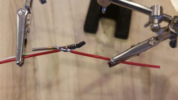
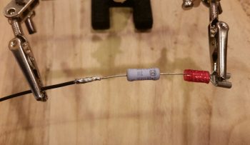
I then joined the wire together, wrapped the lead (“tail”) around the joined wire bundles to secure the wires together tightly, and then soldered the whole affair.
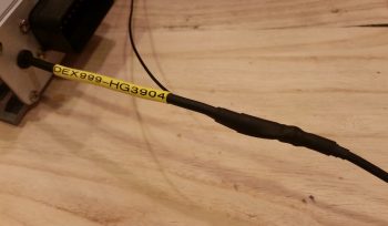
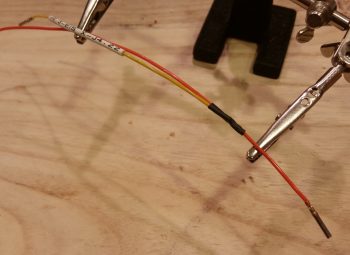
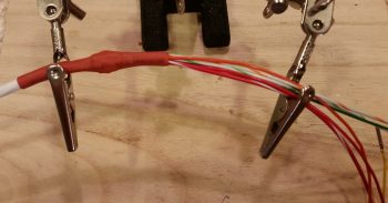
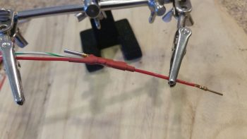
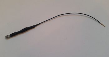
I then added a piece of heat shrink to finish out my ElectroAir EIS Controller ground wire streamlining . . . Voila! Aaah, much better.
•••
1 December 2017 — Today was not only all about planning, but probably even more so about research.
I went down a few rabbit “trails” lets call them, since they weren’t overly exhaustive on time, to verify some of my checklist item entries in regards to the specific equipment I’m using. For example, I’m using the SilverHawk Fuel Injection servo, so I pulled the manual out on that to see how it states the engine starting sequence should be conducted. I also bounced the book answer off what my notes said from many pilots who are flying this fuel injection system in the real world.
Some of my research found updated manuals that now require a different installation configuration that what I had originally had identified. The example here would be the ElectroAir (“Jeff Rose” or “SDS” style) electronic ignition. When I first started the manual stated to use either a fuse or a circuit breaker. However, the latest manual version states explicitly to use circuit breakers. Not a big deal (always a bit more $$ though), but my wiring diagrams depict these circuits using fuses. Thus, I fired off an email to ElectroAir to confirm this info, and included another couple of questions on starting procedures as well.
•••
5 December 2017 — Yes, over the past few days it seems as if I’ve been fighting the un-overcomeable gravitational pull of finalizing my EFIS-loaded checklists. I’ve been wimping out a bit on getting into the cold shop, easily pulled away by the lure of cross-checking each respective piece of electronic ignitions and components that are covered by the checklists.
A big focus of mine on the checklists was finally integrating & deconflicting the engine starting & run-up sequence between the SilverHawk fuel injection, P-MAG EI, and Electroair EI requirements as detailed in their respective manuals. I think my “shakedown cruise” analogy regarding the checklists was correct in that it actually brought a number of issues to light that need(ed) to be worked through.
With Electroair specifically, I found that my fuses were more than adequate as stated by their tech gurus, but then got caught up into two separate discussions with Danny, then Mike, on engine starting methods, sequencing and EI ops in regards to their system’s integration with a P-MAG. Apparently it’s much more common for them to see an Electroair system paired with a traditional mag then it is with a P-MAG. Nonetheless, they were very helpful, I gained some more knowledge about my system, and I got my checklists nailed down for the engine starting & run-up areas.
In addition to all my shenanigans above, I also got some great gouge & specs from Mike Beasley on the throttle and mixture cables install. He gave me some awesome builder tips to assess that I’ll share as I move further along in sorting out the left armrest.
•••
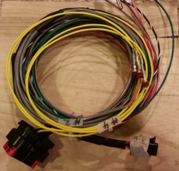
11 December 2017 — Today I got to work on solder splicing a length of 20 AWG yellow wire to an existing yellow lead on the Electroair electronic ignition control head wiring harness (below).
This yellow lead is the one that attaches to the EI “mag” switch for ON/OFF control of the Electroair EI.
I spliced the wires together then soldered it up (I didn’t realize both pics I had of the next steps were blurry until I uploaded them). I then labeled the wire, wound it back up and put the wiring harness away for later.
•••
13 December 2017 — As I mentioned last night, today I started out by doing a decent amount of research in the manuals to see what I could find out regarding my panel issues.
Specifically, I checked some parameters to get a general feel for how I’m going to link the Electroair spark advance display. I think the spark advance meter lead is most likely 12V output, so instead of conveniently hooking up it to my Engine Info box less than a foot away –all neatly stashed away in the GIB’s headrest– I’m going to have to run the wire up to the panel to connect it to the HXr for display. Not a big issue at all, just a bit easier the other route. BTW, AUX inputs to the EIS can only be 5V, thus the reason it would have to make its journey forward in the fuselage.
•••
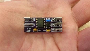
30 December 2017 — Today I got an email from Eric Page, the friendly neighborhood electronics guru off the AEC forum. Eric is close to finishing the tiny circuit board that will have the Bob Nuckolls’ recommended AD626 op amp chip mounted onto it, which will crisply increase the Electroair spark advance signal x10 to allow a very granular input into the GRT EIS box for displaying realtime Electroair electronic ignition spark advance data on my EFIS screen.
Moreover, since it’s currently so cold, today I started working on finalizing my engine info system installation requirements and EIS wiring harness prep. The bottom line here is that I really need to dig into the manual on my GRT EIS4000 unit to get much smarter on it, both from the installation and wiring standpoint, and the operational integration with the GRT EFISs.
So I’ve been confirming all of the connections for the EIS input sensors, and taking a good inventory of each sensor to confirm what will be plugged into each specific port. I’ve already rewickered and refined some resistor placement requirements, and am confirming literally every configuration –both physically and software-wise– for each connection.
•••
3 January 2018 — The last few days has once again been ones of digging into my various engine, engine components and engine sensor manuals both for research and education on the operating limits of each item that will be tracked by the GRT EIS4000 Engine Information System.
As many of you are probably aware, GRT’s EIS Engine Information System was the first product produced by GRT back in 1991 as a result of GRT founder Greg Toman’s search for an automated engine management system for a 2-stroke ultralight engine. Since he couldn’t find one, he simply built one! How’s that for the spirit of homebuilt aircraft?
Barring some sideline and unexpected maintenance issues on my truck, today I was able to get both the initial and secondary (more refined) engine sensor upper and lower limits configured into the EIS unit.
Additionally, Nick Ugolini was kind enough to share his EIS4000 wiring configuration diagram with me as well, which served as an excellent qualitative crosscheck on my configuration. Moreover, my decision to mount the EIS4000 control head in the GIB headrest (i.e. “D-Deck” or “Turtleneck”) was based on Nick’s configuration that he shared on his blog (admittedly, in my ignorance at the time I didn’t think it was best to mount the unit so far aft… but it didn’t take long to realize that it was a great idea).
You might be asking how exactly this EIS control unit mounted in the GIB headrest displays engine data on the panel EFISs. It’s actually very simple in that it relies on one 22AWG wire RS232 serial connection between the EIS4000 and the panel mounted HXr and Mini-X EFISs.
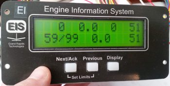
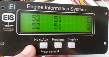
Besides just getting the unit powered up, as you can see in the pics I was able to get some “stick time” on navigating through the EIS4000’s menu pages and getting the initial settings configured. Also, by assessing the configurations on my AUX ports I was able to play the shell game on paper and reassign 3 of the engine sensor connections with newly associated AUX ports which allowed me to avoid major re-configurations of EIS menu items.
•••
5 January 2018 — Today I spent well over an hour updating my engine management system and panel power electrical system diagrams, as well as creating a sheet to cleanly annotate all my current GRT EIS4000 configuration settings.
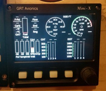
Another nice little surprise at the very beginning of 2018 was a text I received from Marco pointing out an announcement on Grand Rapid Technologies’ website. They are now offering the special features package (EIS data display, Bluetooth and ADS-B display) for free on their Mini-X and Mini-AP EFISs. Well, it ended up that I didn’t qualify for the “free” package, but I found out that I could get it at a greatly reduced price when I ordered my last GRT engine sensor: the Hall Affect Amp sensor.
Since I have Bluetooth and ADS-B on my HXr, I wasn’t concerned about those displaying on my Mini-X. However, I did really want the capability to display engine data on my Mini-X in case my HXr EFIS display died inflight, so I pulled the trigger and ordered the software.
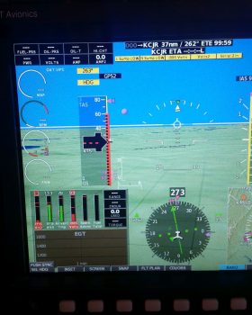
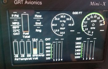
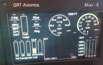
What I didn’t realize was how well laid out the Mini-X engine data display would look (IMO). A few hours after pulling the trigger on the software, I received an email from GRT and was able to update my Mini-X to display engine data. I have to say that I’m really pleased with how it looks (of course, again, these pics don’t do it any justice!).
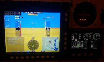
Here’s a wider angle view with the checklist displayed in the lower left inset on the HXr. I did this to simply show that if I was messing about with a checklist, or had a full screen map or approach chart displayed, that with two button clicks I can very easily bring up the Mini-X engine data screen. So, not only is it a great backup feature to the HXr, but it clearly offers a lot of flexibility to provide flight-centric information in a variety of ways.
•••
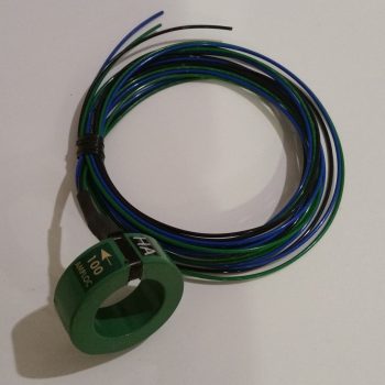
6 January 2018 — When I checked the mail today I finally received the CS-01 Hall Effect sensor that I ordered from GRT. As I was configuring the settings on the EIS4000, I did a quick read on how to set up the CS-01. With it in hand however, today I did some much more thorough research on just how to install the CS-01, including going back and looking at my notes. I had a few questions, and between the GRT forum and the AEC forum I was able to find the answer…. plus a few other nice-to-know tidbits [Note the “HA” code label].
Along with tweaking the settings for the CS-01 Hall Effect Sensor, I had some other updates I needed to do on the GRT EIS4000. So I hooked it back up, fired it up, and tweaked some limit configurations and auxiliary port settings.
•••
8 January 2018 — Today I did some more cleanup on a few more electrical-related docs before getting down to business. After attaching about a dozen wiring labels, I then stripped off some of the heat shrink over the solder splice on the Electroair electronic ignition’s control unit ground wire.
I had removed a Deutsch connector a while back and simply soldered the 2 wires together, but now I needed access to that solder joint to splice yet another wire into the mix: the 22AWG lead that will be the negative input (V- In) to the AD626 op amp board for Spark Advance reporting to the EIS. Again, the signal coming out of the Electroair control unit is too weak so I need to literally amp it up by a gain of 10 so that the GRT EIS can use the strengthened signal to report the Spark Advance to the EFIS screen.
After exposing the original solder splice joint, I then soldered the 22AWG wire into the joint.
I then recovered the new solder splice with some more heat shrink.
•••
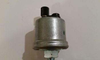
9 January 2018 — Today, as I was tweaking the electrical diagram for the engine systems and EIS4000, I wanted to investigate further a note I had on my VDO HPS-01 Oil Pressure sensor. The manual states that the case must be grounded, but the sensor only includes one terminal for the signal wire. As I went back through my notes I had highlighted a myriad of issues builders had had with these VDO sensors . . . mainly in wonky sensor readings caused by poor or no grounds.
Enter rabbit hole! Well, I wanted to get to the bottom of this since it was a point on my electrical diagram that was cloudy and unknown to me. I wanted an answer to this riddle so I could press forward with this variable turned into a constant. After an hour or so of researching my notes, manuals, forum posts (mainly VAF) and other notations, even from canard heavyweights like Marc Zeitlin, I came to the conclusion that my VDO oil pressure sensor, did “in fact,” need a grounding tab attached to the case as spelled out by the EIS4000 manual, et al.
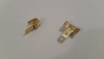
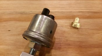
I looked online for these tabs, and after not being able to find a source of supply, I decided to construct one myself from some multi-connnecting Fast-ON tabs I had on hand. I simply bent the wings of the female connector out to then create curved “wings” that could then be attached to the case of the VDO oil pressure sensor.
Patting myself on the back for my sheer ingeniousness, I then read up on brazing vs. soldering, concluding there that with brazing being generally 5x stronger than soldering, I should “in fact” go that route. I perfected my expertise by watching a few YouTube videos on brazing, and with my newfound knowledge in hand I ran down to Lowe’s and grabbed some bronze brazing rods. Ah, my plan was coming to fruition!
I got home, cleaned up both surfaces to be brazed with steel wool and then some wipes with Acetone.
I had let a wood board soak in water while I was gone and used that as the underlayment for my project. Yes, all ready to go!
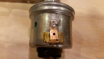
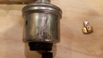
And then the “fun” began…. with my portable propane torch I attempted to get this baby red hot. Well, after not doing that, but inadvertently burning some of the plastic assembly on the top side of the sensor (merely cosmetic) and realizing my best attempts of getting any bit of the brazing material to lay down was a lesson in futility, I called it quits.
Hmmmm?!?!?!
I then decided that since I had a fair bit of surface contact between tab and case, I would try my hand at soldering the tab onto the case. Again, no joy! The case seemed to be impervious to any attempts to attach anything to it! Crazy . . . .
Here’s the sad aftermath of my attempts to attach a grounding tab to the side of my VDO oil pressure sensor.
Now, here’s the kicker. I did learn a lesson in all this. After failing miserably above, I went back into research mode. What was the deal with this VDO sensor? Did they make others (they do) with a terminal for a ground wire (they do). Hmmmm? So I uploaded all my pics, put my notes in my blog to finish in the morning, and then called it quits for the evening.
However, as I was getting ready to head to bed, I was looking through pics of installed VDO oil pressure units in aircraft. Now, I knew if it was installed straight to the engine case (which is a no-no in itself) that it didn’t need a ground wire since the case was grounded. But I was seeing pics of remotely mounted 1-terminal VDO oil pressure sensors like mine WITHOUT a visible grounding wire!
What gives?!
Thus the need for my ground wire . . . or . . . wait a minute! Ahhhhhh! I quickly did a continuity test on my engine sensor manifold block and –Voila!– it’s conductive! I got a solid tone with one probe on one end and the other probe on the VDO oil pressure case at the farthest point I could get from the first probe.
Thus, my ASSUMPTION that the manifold block was a non-conductive aluminum spun me off on a wild goose chase and caused me literally hours of un-needed effort! Combine that with the note on the GRT EIS4000 diagram that states: “The case of the sensor provides a ground connection for VDO type sensors.” I had simply allowed the word “case,” combined with all the horror stories and accounts of the requirement to attach a grounding tab lure me down a road that was entirely unnecessary!
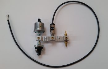
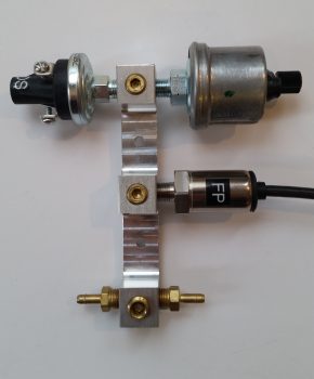
Ok, so here’s a shot (I cleaned up the nasty brazing/soldering marks off the VDO oil pressure sensor with steel wool earlier) of my engine sensor manifold with the sensors attached. The top left is of course the VDO oil pressure sensor that sends a signal to the EIS4000. The sensor beneath it is a simple backup oil pressure switch that drives a “Low Oil Pressure” light on the AG6 warning annunciator in case I lose my EFIS, EIS, etc. The sensor with the black cable running out of it is the Fuel Pressure sensor. On the right you can see 2 brass barbs, one is for the PMag MAP tube and the other tube runs through the firewall into the hellhole where the Electroair and GRT MAP sensors are located.
At this point I’m not sure exactly where or in what orientation the engine sensor manifold block will get mounted, so I included a pic showing it oriented vertically.
•••
12 January 2018 — I took the video below to demonstrate the function of the instrument panel On/Off indicator lights’ Push-to-Test button and dimmer features.
I was so pleased at how both the dimmer and the Push-to-Test functions were working that, again, I decided to make this video. To reiterate, in the video I briefly touch upon the new Mini-X Engine function display page.
•••
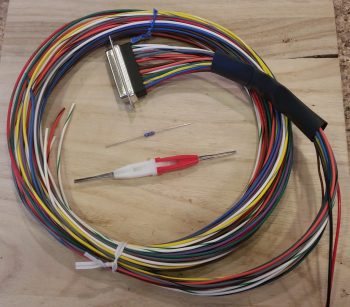
13 January 2018 — I started out today gathering up my GRT EIS4000 wiring harness, a 300 Ohm 1/4w resistor, and my D-Sub socket removal tool. My task here was to add a cross connect wire from the EIS4000’s blue 4.8V excitation wire to the engines oil pressure sensor’s EIS signal input lead. This is required to ensure the ~5V signal strength is maintained at the oil pressure’s input port on the EIS unit. Physically, it is simply a cross-connect wire from the blue to the orange/black wire in the EIS4000’s wiring harness.
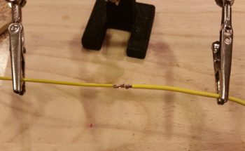
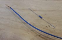
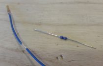
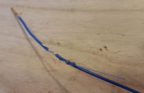
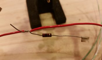
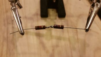
I started off by removing the blue wire from the D-Sub connector, then trimmed about a 1/4″ of the insulation off of it a few inches from the D-Sub socket and then wrapped one of the resistor legs around the exposed wire segment.
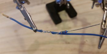
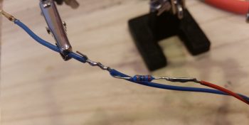
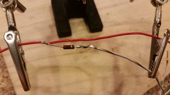
I then soldered the resistor to the exposed wire segment on the blue 4.8V wire. Next, I soldered a short length of 22 AWG orange/black cross-connect wire to the other leg of the resistor.
I then trimmed up any protruding sharp edges and enshrined my work in red heat shrink.
On the EIS4000 oil pressure sensor port’s orange/black lead I then exposed about a 1/4″ of bare wire just as I had done on the blue wire above, only this time it was 4-5″ downstream of where I had tapped into the blue wire. I then wrapped the stripped end of the cross-connect wire around the bare part of the oil pressure sensor wire….
and soldered the cross-connect wire to the oil pressure sensor wire.
I finished off my task with another round of red heat shrink over the cross-connect/oil pressure sensor wire solder-spliced junction.
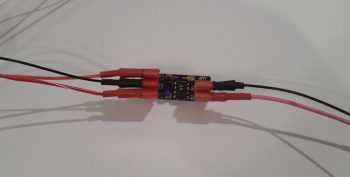
In other news… I finally received my Bob Nuckolls recommended and Eric Page built AD626 Op Amp board (for displaying Electroair Spark Advance on the EFIS via the EIS). Once again Eric did a phenomenal job constructing this board. I really like his concept of using PIDG FastON tabs for connecting wires to the board…. nice & EZ! Moreover, I’m extremely thankful that we homebuilders have a corroborative means such as the AEC forum to figure this stuff out. Such an excellent resource.
Although I won’t have any wire labels until Monday, thus keeping me from completely wiring up the AD626 Op Amp Board, I did start prepping the EIS wiring harness with connective wires to connect to this rather diminutive component. As an aside, the FT-60 fuel flow connects to a 12V+ port on the EIS4000. In addition, the manual specifically states to use this 12V+ port to connect the Fuel Pressure sensor. Thus, since I have 12V power at the ready (the AD626 Op Amp board uses very little power), I am merely going to tap into the EIS4000’s 12V+ port to drive the AD626 Op Amp as well.
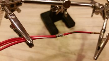
Pictured below are 2 wires connected to the bared 1/4″ section (just like above) of the EIS4000’s 12V+ out power port, making 3 out leads from this one port. The longer original Red/Blue lead is for the FT-60 Red Cube Fuel Flow Transducer. The next longer Red/White lead is for the AD626 Op Amp board, while the shortest red lead is for the Fuel Pressure sensor lead.
I then soldered the 2 added power wires to the EIS4000’s 12V+ out lead.
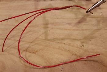
And then added some heat shrink to the solder joint.
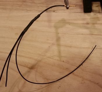
I pretty much did the same thing as above for the ground side of the circuit by tying into the EIS4000’s ground wire.
•••
15 January 2018 — I hit another milestone today as I finally got the Electrair Spark Advance AD626 Op Amp board wired to both the GRT EIS4000 and the Electroair control unit. When I do the final install on the op amp board I’ll use a big piece of heat shrink to keep all the connectors in place.
Here’s a closer look at the Spark Advance AD626 Op Amp board with complete wire connections.
•••
16 January 2018 — My major push of the day was a 6-wire cable that I bought from Stein to manage and clean up a “myriad” of the single 22 AWG wires heading from in front of the panel to the D-Deck & Hell Hole areas in the back. For a very minimal weight penalty, I now have six 22AWG wires bundled together for their journey aft (or forward…). The 6 “chosen ones” for these wires are as follows:
- Engine data from EIS4000 to HXr & Mini-X
- Serial link from HXr to EIS4000 (for EIS software updates)
- EIS alarm output to AG6 warning annunciator
- Back-up Oil Pressure sensor power/alarm to AG6 warning annunciator
- Hobbs meter power
- “Starter On” alarm to AG6 warning annunciator
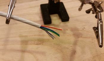
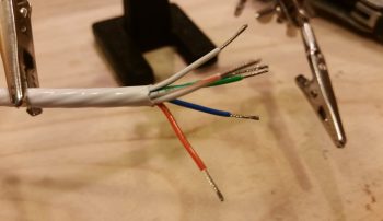
Today my focus would be on the forward (panel) end of this 6-wire consolidation cable. I started by stripping back the outer insulate that then allowed me to strip the ends of the wires for connection to their respective final end-point runs.
Before I connected the orange wire that provides engine information to the HXr and Mini-X, I soldered in a quick jumper wire that sends the signal from the EIS4000-to-HXr connection (J4 connector) simultaneously through the yellow jumper wire to the Mini-X (J3 connector). Note that I created the 1/4″ bare-wire gap in the orange wire using my wire strippers, then trimmed the overhanging wire off the end when I terminated the wire with a D-Sub socket.
I then soldered the yellow jumper wire to the 1/4″ bare-wire section on the orange wire.
And covered the solder splice with some protective heat shrink.
With my initial jumper wire addition task out of the way, I then got busy soldering all the final extension wire runs into place onto the wire ends of the 6-wire cable.
And then covered all the solder splices with protective heat shrink.
I then finished up the extension wire run attachments with another couple pieces of larger red heat shrink.
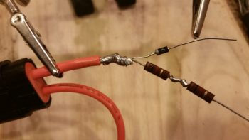
After double-checking my wiring diagrams, I realized I needed another branch off the backup oil pressure sensor’s power lead to drive the AG6 warning annunciator (whenever the backup oil pressure sensor is in an alarm state). However, as per the AG6 manual, this branch run to the AG6 requires an inline 2K Ohm resistor. Ah, and for some reason (wink) I just happen to have some on hand! So I bared yet another segment of wire on the backup oil pressure sensor’s red wire extension run and twisted a leg of the resistor into place.
I then soldered both the resistor connection to the backup oil pressure sensor’s red power wire extension run and white/brown lead to the actual AG6 annunciator.
I then covered all that up with some red protective heat shrink.
I spent another fair bit of time printing out wire labels and attaching them to the 6-wire consolidation cable front side wire extension runs. I also terminated all the ends of these leads accept the ones headed to the AG6, since those simply get terminated into block terminals on the AG6.
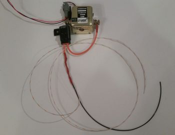
Here’s the half finished 6-wire consolidation cable:
Of course figuring out the front side of the 6-wire consolidation cable meant determining the aft-side interfaces with the EIS4000. During the process of building the cable above, I would fix other issues as I ran across them. For example, now knowing that the panel On/Off LED indicator lights dim and push-to-test functions work, I cut, labeled and terminated the lead that goes from the PTT switch #4 to main bus power.
I also gleaned even more wires from the EIS4000 wiring harness, swapped some GRT wires for better quality Tefzel wires (I’m not a fan of the quality of wires that came on the EIS4000 <specifically> and swapped out 2 of the 3 wires that run into the engine compartment). In addition, I swapped some colors out to better align with the components they were connecting to (say, yellow to yellow, etc.) Finally, I labeled the majority of the wires in the EIS4000 wiring harness.
•••
17 January 2018 — Today I got all the wires labeled on the GRT EIS4000 Engine Info System wiring harness. In addition, I was able to label the wires near the actual GRT Manifold Pressure sensor and the GRT Hall Effect sensor. Since I ran out of wire labels —having burned through 2 cartridges in less than 3 days— the labels on the distant end of these wires (where they connect either to the EIS4000 or to ground) will come later. Lastly, I was able to label 2 out of the 3 wires coming out of the left and right fuel tank level sensor control heads.
As you can see, I clearly made a sizable dent in the aft fuselage-located components’ wiring labels.
I then spent a couple of hours researching and doing some initial messing about with configuring my engine data info display on my HXr EFIS screen. After seeing and assessing how I can go about configuring it, I got into the manual to find that I missed a HUGE piece of the installation puzzle . . . again, assumptions will bite you in the butt!
Since the EIS4000 is a standalone panel mounted instrument in its own right, but that can also be summarily hidden away so it’s sexier cousin (HXr) can get all the praise in presenting such wonderful data in bright shiny ways, all the parameters on the EIS4000 must be zeroed out with all the engine data max/min limits set in the EFIS. Why? Well, if an alarm rings off on the EIS4000 (remember, it’s a standalone instrument that shares its data with the HXr EFIS) with it tucked behind the GIB’s head, then there is no way to turn the alarm off!
Thus, by zeroing out the engine data parameters in the EIS4000, it then becomes an information collection point and conduit to further pass the data (and parameter limit control) to the HXr. So along with deciding what exact info I want displayed, and how, a new task on my list is to now transfer all the engine data parameter limits from the EIS400 to the HXr (and Mini-X) and then zero out the engine data parameter limits on the EIS4000 box (except for the Aux functions… those are simply replicated between the two units).
•••
21 January 2018 — Today, with no wire labels on-hand, I was once again limited in all that I could accomplish to finality.
My specific focus currently is on both the GIB headrest/D-Deck/TurtleDeck AND Hell Hole located components. Since I have the EIS4000 and the Electroair EI control unit mostly configured and labeled (although I need a few more labels for the Elecroair wiring harness), today I set my sights on the B&C SD-8 backup alternator wiring.
The components for the SD-8 live in 4 distinct places within the aircraft.
- SD-8 alternator mounted on engine vacuum pad
- SD-8 Voltage Regulator, Bridge Rectifier and Capacitor in D-Deck/GIB headrest
- SD-8 power relay in the Hell Hole
- SD-8 main connection feed into aircraft electrical system at the battery contactor
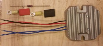
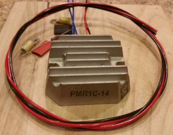
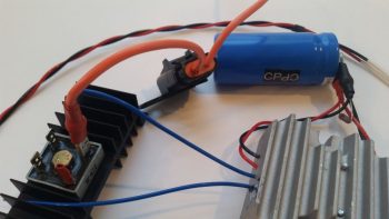
I started by wiring up the dual leads that exit the robust blue capacitor (although not pictured until later below) and head to the SD-8’s PMR1C-14 Voltage Regulator and to ground and power relay, respectively. I gathered up all my required components, including a 1K Ohm, 3 Watt resistor that gets placed across the terminals of the capacitor.
I then went down to the shop and got a good approximate length required for cutting the black & red 14 AWG leads. Again, these will get terminated with the associated lead colors on the voltage regulator, and then the black will head off to the “forest of tabs” grounding block in the Hell Hole, while the red will head off to the SD-8 power relay, also located in the Hell Hole.
I then crimped the large yellow screw post PIDG connectors to the black & red leads, with the interconnecting 1K Ohm, 3 watt resistor. Again, these leads will get attached to the quite hefty blue capacitor for the SD-8 backup alternator system. [I had to hold off on the blue Voltage Regulator leads since they get terminated with the big white 12 AWG SD-8 power leads that I soldered extensions to below]
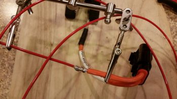
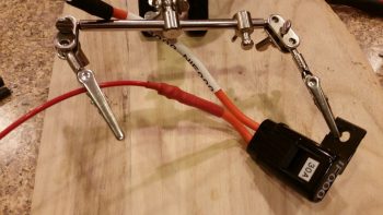
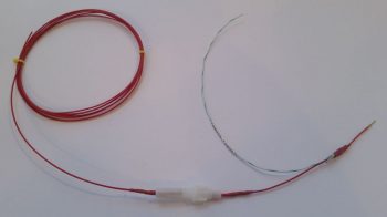
 I then went to the other end of this equation, literally, to attach the 14 AWG red power feed wire that runs from the SD-8 backup alternator to the battery side of the battery contactor in the nose, all via the inline 30 Amp ATC fuse. I spliced the red SD-8 power feed wire to this inline 30 Amp fuse (IF000).
Then I finished the job with a couple of layers of red heat shrink over the solder splice. Again, this 30A inline fuse (IF000) resides in the nose battery compartment, just below the battery contactor and nose tool box.
I then again headed down to the shop to get a very close approximation for the total length of wires I would need for the SD-8 alternator power leads. These wires exit out of the SD-8 alternator unit and then get terminated onto the SD-8 bridge rectifier (along with the blue SD-8 voltage regulator leads) in the D-Deck/GIB headrest. I cut the white 12 AWG wires and then did a rather intricate interweaving of the 2 sets of wires on each lead to add a lot of strength to the wires before I ever even hit the splices with solder.
I then soldered up these massive spliced joints.
And then covered each spliced joint with multiple layers of red protective heat shrink.
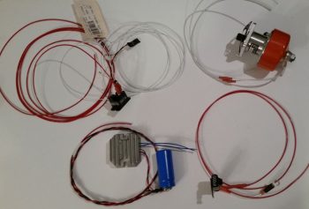
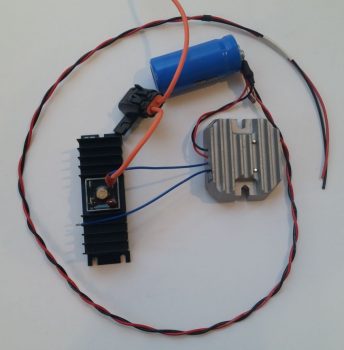
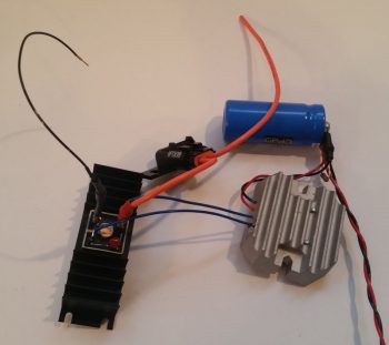
Here’s a shot of all my SD-8 related wiring effort today. I also refined my drawing of the GIB headrest/D-Deck to nail down how the components will be mounted within it. Note the SD-8 Voltage regulator leads are connected to the blue capacitor. Also note the unmentioned SD-8 power relay leads’ terminated into the relay. The small little black nodule hanging off the relay is the backup Alternator’s Over-Voltage protection module that prevents any major damage happening to the electrical system if the SD-8 enters an overvoltage state.
Finally, while not SD-8 related, since the Hobbs meter will reside in the GIB headrest as well, I went ahead and wired up the negative side lead that will traverse the firewall to connect to the backup oil pressure sensor. I originally wasn’t going to have a Hobbs meter, but since I installed the backup oil pressure sensor I figured for 1 extra wire and about an ounce in weight I would have a good crosscheck for my engine/airframe time.
•••
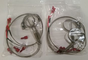
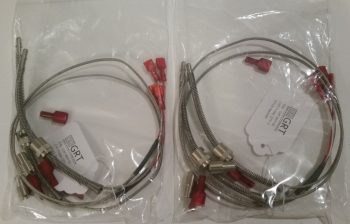
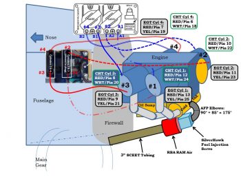
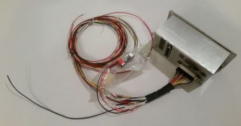
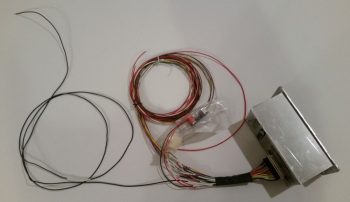
22 January 2018 — While collecting up parts and components for the engine build I finally took a good look at the GRT EIS4000 Engine Info System Connector B wiring harness that contains the wire leads to the engine CHT and EGT probes. However, after digging around in the box I didn’t find anything else other than what is pictured below, so I sent an email to GRT with the pic asking for clarification on just the exact CHT/EGT stuff I was supposed to get with the EIS4000.
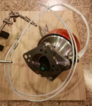
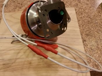
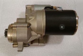
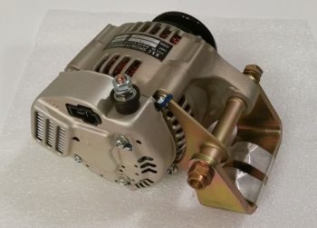
Since I haven’t taken pics of the shy B&C starter and its closest buddy –also shy– the B&C 40 Amp alternator, I thought I’d do so before they get mounted to the engine.
 Now, both the Canard Pusher newsletters and B&C touted this starter as “lightweight” and maybe it is compared to other starters out there, but man, when I was dragging this and the alternator down off the shelf in the shop I thought…. that’s a lot of combined weight for the very aft point of the engine, no wonder Burt wanted us to hand prop these birds!
Here’s the shy twin: the B&C 40 Amp alternator. Looks like a quality piece of equipment . . . very robust.
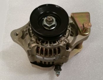 And one final shot of the B&C 40 Amp alternator before it goes back in the box to get mounted on the engine in the next day or two.
•••
24 January 2018 — Today I called GRT and solved the case of the missing EGT & CHT probes…. they are sending me the sets for my engine (an oversight on their part, but they are remedying it in an expeditious fashion).
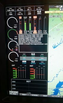
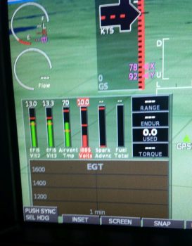
I then got to work on setting up my engine data display on the HXr EFIS. I’d like to point out a few things in the pic below. First, note column #3 “Airvent Tmp” and column #5, “Spark Advnc” in the lower left inset. Next, note the yellow “L Sump LOW” and “R Sump LOW” alarm states across the top, which not currently being hooked up to the low fuel sensors they alarm due to no signal…. I also got some more refined info on dialing in these Sump Low Fuel alarms from GRT as well. Finally, note that in column #1 I have a low voltage alarm on EFIS Voltage 2, which is the E-Bus feed to the HXr.
Since not all data points are available to each display area. For example, the vertical data columns in the inset don’t necessarily have the same data points to display as say the 4 black combo boxes stacked up in the upper right corner of the inset. I played around with these a while until I finally got the data showing that I wanted.
I then went to the split screen engine data page. Note that my #2 EFIS power input is still red in the pic below. Also note the new red numbers in the EGT and CHT graphs at the bottom, which is showing up since I set the limits.
I finally took a moment to see why my EFIS Volts2 input source was alarming, and quickly discovered that I had no fuse in the E-Bus slot where the HXr connects to… so I popped a fuse in, and no more alarm. However, I would like to point out even further the bus power source data below. Column #2 in the inset is EFIS Volts3 power input which comes from the X-Bus, or IBBS. Now –since the IBBS is not installed– it’s simply jumpered off the Main Buss, so those two busses read the same: 13.3V. But the E-Bus voltage reads 13.0V. Why? This is due to the Schottky diode that lies in the middle of the connection between Main Bus and E-Bus. Schottky diodes extract a toll for their services, often up 0.7 of a volt just for being in the picture.
After setting all my engine data limits, inputs and parameters in the HXr, I then did the same in the Mini-X. I made a few quick changes right off the bat like changing out the Carb temp reading in the upper LH corner to “MPG.”
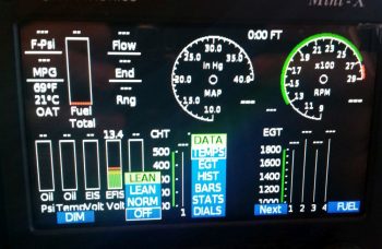
I then did a bit of exploring and found a few cool things: such as the 6 different engine page display types on the Mini-X.
Here is DATA menu #2: EGT as shown above that I selected. I also set some display parameters like dropping down the max RPM on the dial from 3000 to 2800 RPM. Note that it will still display the actual numerical RPM if it goes above 2800 RPM (the dashed lines at about the 4-O’clock position of each dial), it just doesn’t show it on the dial. The reason for narrowing the dial’s range is that it actually makes it more readable since it increases the granularity on those setting numbers displayed (i.e. makes the space bigger between the numbers) in the normal operating range. If it goes above say, 2700-2750 RPMs, it will definitely let me know!
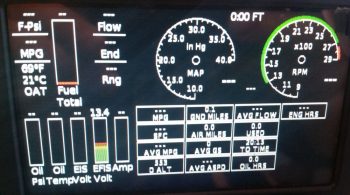
Here’s another page: STATS.
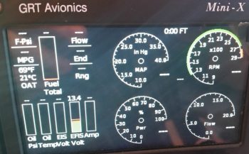
And lastly, a dials page that adds % power and fuel flow in dial format.
After spending a bit of time configuring all the EIS display settings and inputting all the limits and parameters, I then zeroed out all the limits on the actual EIS4000 box. Thus, until I fire the engine up and taxi around, I’m pretty much done with programming engine data stuff on the EIS. It will truly be just a matter of fine-tuning the numbers from here on out.
Which reminds me, one of the diagrams I updated was on the SD-8 back-up alternator system. My fellow local Canardian, Ron Springer, posted a question on the AeroElectric Connection forum regarding a 15A fuse shown on the B&C wiring diagram for the SD-8. On the diagram it shows this inline 15A fuse residing between the SD-8 Alternator and the voltage regulator.
In Bob Nuckolls’ AEC book, he adds a Bridge Rectifier to the SD-8 circuitry which provides a self-excitation feature, which makes it so the SD-8 doesn’t need to see power coming from the battery to “turn on.” However, in the various circuit diagrams Bob has, there is no mention or depiction of this 15A inline fuse.
So I jumped into the fray and asked Bob specifically about this fuse (there was some confusion as to exactly what fuse was being discussed, so I offered my “clarification” services . . . haha!). Bob replied with:
 I'd forgotten about that fuse being
 added some years ago. It's a good idea. One of
 the failure modes for the rectifier/regulator
 places a dead short on the SD-8 output. The fuse
 keeps the dynamo from smoking. The RMS current
 flowing out of the dynamo is about the same as
 the DC output current from the rectifier/regulator.
Thus my reason for adding the 15A inline fuse back into the mix, and of course updating the Charging System electrical diagram to reflect this change. Amazing that after all these years Ron sparked a discussion on that fuse just days prior of me needing to get a final answer on that specific fuse in order to proceed.
•••
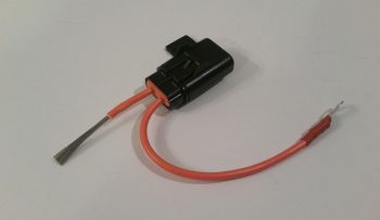
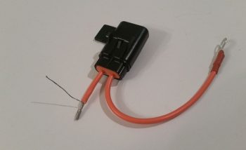
25 January 2018 — Today I started out by extricating the fuse junction off the back of the Fuel Vapor Sensor control head to repurpose it for the X-Bus power feed to the EIS4000. As I was reviewing the EIS install manual I noted a specific statement that the power wire should be fused… and since it’s quite a lengthy wire back to the D-Deck I figured although the IBBS feed to the X-Bus is fused, I would throw an inline fuse in place. I wanted a less bulky fuse housing than the ATC blade inline fuses provide –with their gargantuan leads no less– so I stole this one from the Fuel Vapor Sensor.
Then I made a boo-boo. Not unrecoverable by any means, just really dumb. I consider it especially dumb since I had all the tools I’ve worked so hard to make available to me to keep this stuff from happening: electrical diagrams and wire labels. If I had used either one, then the extra silly work I had just created for myself below would have been avoided!
For my power lead from the X-Bus (IBBS power) to the EIS4000 I need a wire lead to the AG6 annunciator for a general EIS alarm that will ring off. This wire is connected to a pigtailed resistor (required by the AG6). In addition, to make it easy, I have a D-Sub socket awaiting the actual alarm lead from the EIS. Well, I grabbed the first setup that remotely looked like this off the X-Bus, pulled it and realized that I had “forgotten” to add the actual power wire to the equation. Well, I hadn’t FORGOTTEN, it was merely that I pulled this same style setup for the IBBS low voltage sensing wire and AG6 IBBS Low Volt alarm from PIN 1! The EIS power wire and AG6 reporting belongs on PIN 7! I had grabbed the wrong setup in my haste and was charging forward, oblivious to my error…
So here goes: I trimmed the length of the 20 AWG fused lead that I had just stolen from the Fuel Vapor Sensor control head and bared about 1/4″ of the wire a bit away from the end that terminates into the X-Bus (DB9 connector). One thing good about my mistake here is that since I built the X-Bus I’ve come to know well the importance to give at least a good inch or two of clearance on these D-Sub wires before placing any components or splices on the line to allow easier removal of the D-Sub terminated wire from the connector…. which is what I did here.
I then soldered the AG6 lead/interface/resistor combo to the bare spot on the power wire (not before soundly wasting another D-Sub pin by removing it!).
And heat shrank the junction.
Here’s the entire assembly from X-Bus termination (right side NEW D-Sub pin) up to the inline fuse assembly. Ok, note the wire label on the white/green wire… it literally says TXB001 –for a quick refresher on my wiring code, that translates to LOCATION: “T” or Triparagon, ITEM CODE: “XB” for X-Bus, and PIN #: “001”– …. right there, literally in black and white, staring me in the face! Ugh.
I then solder spliced a long length of 20 AWG wire to the other side of the fuse connector (process not shown) and added heat shrink. Here’s the EIS power wire assembly connected to the other side of the inline fuse terminal.
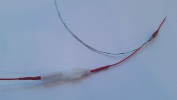 And the entire fused EIS4000 power feed and AG6 alarm input. To be clear, the alarm lead from the EIS is one of the 6 wires in the 6-wire cable that I just made up last week.
It wasn’t until I went to mount this assembly into pin 7 on the X-Bus (Yes guys, I seriously even knew this by heart . . . total brain fart!) that I realized that’s not where I removed it from. Hmmm, what’s going on here?? I wondered in confusion. Then when I actually read the wire label on the white/green wire, and checked my wiring diagram I finally realized I screwed this thing up 10 ways ’til Sunday.
Now I had to remake another lead for the X-Bus IBBS lead that I just heinously stole for the EIS power lead (which clearly I had never made in the first place…). No big deal, it took a few minutes to find my resistor stash. Just like the one I stole, it gets an AG6 feed wire and a D-Sub socket for future connection to the IBBS lead, both connected on the downstream side of a resistor. This is very close to the same setup as the EIS power wire, but since the IBBS lead simply monitors the X-Bus voltage, it doesn’t need any other wire other than the input into the X-Bus (thus why I thought I had “messed up” on originally creating the EIS power lead . . . which of course wasn’t the EIS power lead).
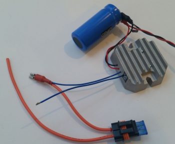
Moving on with my newfound knowledge straight from the keyboard of Bob Nuckolls, I grabbed one of the inline ATC fuse assemblies with mondo-massive wire leads and did some mental configuring where all of it would be situated in its D-Deck/GIB headrest habitat. I then trimmed one lead a little shorter on the inline fuse, gathered up a yellow FastON connector and some red heat shrink and went to work. The way this works is that both blue leads coming from the SD-8 voltage regulator get connected to the leads coming off the actual SD-8 alternator. The one change as of now –within the last 24 hours– is that one of those leads to the engine-mounted SD-8 alternator gets an inline 15A fuse.
So that’s what I did here.
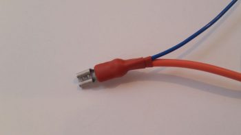
Here’s the blue lead from the voltage regulator spliced with the inline fuse lead of one the SD-8 alternator leads combined into a PIDG FastON connector.
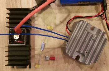
I then threw the Bridge Rectifier into the mix where it belongs so that you can see where this FastON connector actually gets connected into the SD-8 power matrix. The other blue lead from the voltage regulator, combined with the other lead of the SD-8 alternator into another FastON connector, will get connected to the lower left tab of the bridge rectifier shown below. I also need to order a 3K Ohm 3 watt resistor for the final connection to make the SD-8 circuit ready for prime time install. This resistor will be the start of a ground wire that connects to the upper left tab of the bridge rectifier. Again, all that’s left after I make up that ground wire is to install this thing. (The black lead of the twisted pair goes to a Hell Hell ground tab while the red wire goes to the SD-8’s Hell Hole-mounted S704-1 relay that I showed in a post last week).
Here’s a bit closer shot of the components I highlighted above.
•••
27 January 2018 — This morning I spent a few hours replying to emails and updating my electrical diagrams in what appears to be a fairly controversial move on my part. I’ll start by providing some background on my quest to find information on optimizing the firewall components’ layout and engine wiring transition through the firewall.
I remember reading about Brian DeFord’s Cozy burning up on the ramp due to an electrical issue at the firewall. I’m still not 100% clear as to what caused it, as he may not be either. It was a tragedy and I’m sure heartbreaking for Brian, but I’m glad both he and his beautiful family were safe from harm in this incident. One thing that Brian mentions is that he did not turn off the master switch at the first telltale signs of smoke, and within 20 minutes his stellar Cozy IV lay in a pile of ash with only the engine and winglets pretty much left.
This led of course to some major discussions on the Cozy forum and other venues about hot wires transiting through the firewall. In my research I discovered a question asked by Greg Norman [I know Greg from RR16] to the Cozy forum specifically about mounting the starter contactor/solenoid on the cold side of the firewall. There was fairly overwhelming consensus in those that replied that stated mounting the starter solenoid on the cold side of the firewall kept from having to have the big power wire traverse the firewall.
As I assessed this, I came up with a number of pros as to why I concurred that it was a good idea:
- In keeping the main power cable from transitioning through the firewall, it simplifies the corrective action for smoke or malcontent coming from the engine compartment in that the only hot wire going through the firewall (before start… after start there is of course the alternator B lead) is caused by the starter button/switch being engaged. To remedy a hot wire to the starter and cut power one merely STOPS pressing the starter button/switch.
- As per above, this makes turning off the Master Switch less of a critical step to remedy something electrical-related being amiss in the engine area to more along the lines of probably a good idea thing to do.
- The ancillary logistical benefits of moving the starter contactor to the cold/forward side of the firewall in routing wires is quite significant. It simply makes for running less wires through the firewall, wire runs to the Hall Effect sensor for both the primary and SD-8 backup alternators are optimized, and it places more items in the rather empty Hell Hole area and gets them off a very crowded firewall, just to name a few benefits.
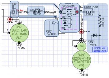
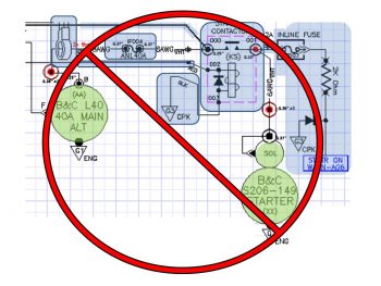
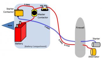
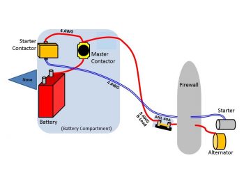
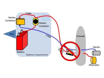
- Below is a diagram I made to explain this. Prior to my decision to move the starter contactor forward to the cold side of the firewall, everything in the diagram below was mounted on the hot/aft side of the firewall. The main big power cable coming from the nose mounted battery contractor is the big line at the very top left half of the diagram. Now that I’ve moved the starter contactor (planned, not executed …. yet) everything in blue is on the cold/forward side of the firewall while the alternator and starter are of course still mounted to the aft side of the engine.
Thus, in short, moving the starter contactor forward to the cold side of the firewall just really appears on the face of it to make for an easier install and a safer operational setup. Honestly, I might not have done it if there wasn’t the overwhelmingly increased ease of wiring it provides.
[I should note that I posted this as a question on the AeroElectric Connection forum, and in my discussion with Bob Nuckolls he does NOT seem to be a fan of moving the starter contactor to the forward side of the firewall. I will also state that I have not received any clear reason from anyone, including Bob, up to this point as to why it would NOT be a good idea. I have had a number of Cozy/Canardians say that they are or have done this, and are glad to have made the change. Understandably, the folks who seem the most unenthused about this idea are not canard/pusher pilots/builders, but tractor aircraft drivers].
Moving on from the controversy, today I received the missing EGT probes from GRT…
and the missing CHT probes. Thus I’m calling The Case of the Missing EGT & CHT Probes SOLVED!
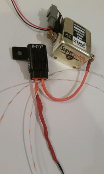
I then got to work on at least getting one electrical task knocked out today. Since I was already dealing with the starter contactor I decided to build the circuit that is used by the AG6 warning annunciator to alarm during engine start with a “Starter ON” annunciation. If this red alarm annunciation does not turn off after engine start, or after a failed start attempt, then it tells me that the circuit is still live and that I need to take immediate corrective action (probably very close to what happened to Brian DeFord in his Cozy burning-up incident).
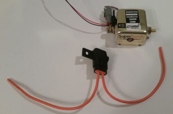
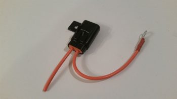
The circuit for the AG6 Starter ON warning cohabitates with the Starter lead on the downstream side post of the starter contactor, starting off with a 2 amp inline fuse [Note: The wiring diagram for my task here is shown in the diagram above on the right side of the page]. I grabbed another mondo-wired inline fuse assembly and assessed its eventually mounting in the vicinity of the starter contactor.
I then trimmed one leg down a bit, stripped the wire back and crimped a blue PIDG 0.25″ ring connector onto the end of the trimmed inline fuse leg. When I crimped the terminal in place I clocked it so that it would be vertical while the body of the inline fuse housing was flat against the firewall. Of course I had preloaded the wire with a piece of red heat shrink to place over the terminal after I crimped it.
Here’s another shot of the 2 amp inline fuse for the AG6 “Starter ON” warning annunciation lead.
I then hacked off the other leg a little over half-way.
I stripped a big portion of the insulation away.
I then teased out around 4 wires to create a pigtail for wrapping around the component leads for a tight junction when they would get soldered onto the lead.
When I talked to Rich at Aircraft Extras regarding the installation of the resistors for the AG6 warning input leads, he said the install manual required 2K Ohm 1/2 watt was a good ballpark for what can be used. After that discussion, I’ve used 1.5K Ohm and 1/4 watt resistors on other AG6 leads without any concern. But here, with this being connected on the same post as the one item that sees the biggest inrush current on the entire aircraft, I wanted to go with what’s called out in the AG6 install manual…. as a minimum.
The problem was I was out of 2K Ohm 1/2 watt resistors. Hmmm? Ok, well, I guess two of those 1K Ohm 1/2 watt resistors in series will just have to do! So, I improvised, adapted and overcame … and pressed forward with my 2 resistors in series.
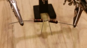
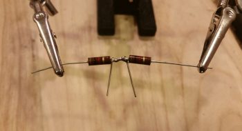
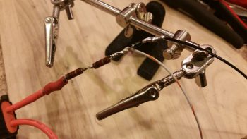
I then soldered the two 1K Ohm 1/2 watt resistors together….
and trimmed the excess leads.
I then (mistakenly . . . sheesh!) tied the resistor set and a diode together at the end of the 2A inline fuse lead.
And soldered that up. But something wasn’t right. Yep, strange things were afoot at the Circle K. When I checked my diagram I quickly noted that I had tied in the diode at the wrong point.
So I snipped the diode off and soldered it in parallel with the white/orange lead that heads off to join up with the white/orange lead from the 6-wire cable that heads up to the panel avionics area. The diode that I relocated is a protective diode that simply goes to ground and protects the line from any massive amounts of juice from frying anything.
I then added protective heat shrink to the whole shebang and called it good.
And then did some labeling of the inline fuse housing (“IF007”) as well as the inline fuse housing I configured for the SD-8 the other day (“IF008″… not shown). Of course when I get some more wire labels here in another week or so I’ll label up all the unlabeled wires I’ve just created over the past week.
•••
28 January 2018 — I spent a number of hours today researching different options for relocating the starter contactor off of the hot side of the firewall in order to eliminate the need to have an essentially always hot robust power cable (whenever the master switch is on) running the length of the cabin. I’ve been in discussions with a number of builders, and will continue to assess this issue. Nothing dire, I would just like to optimize my electrical system configuration where possible.
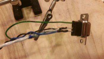
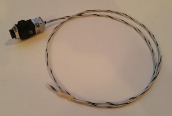
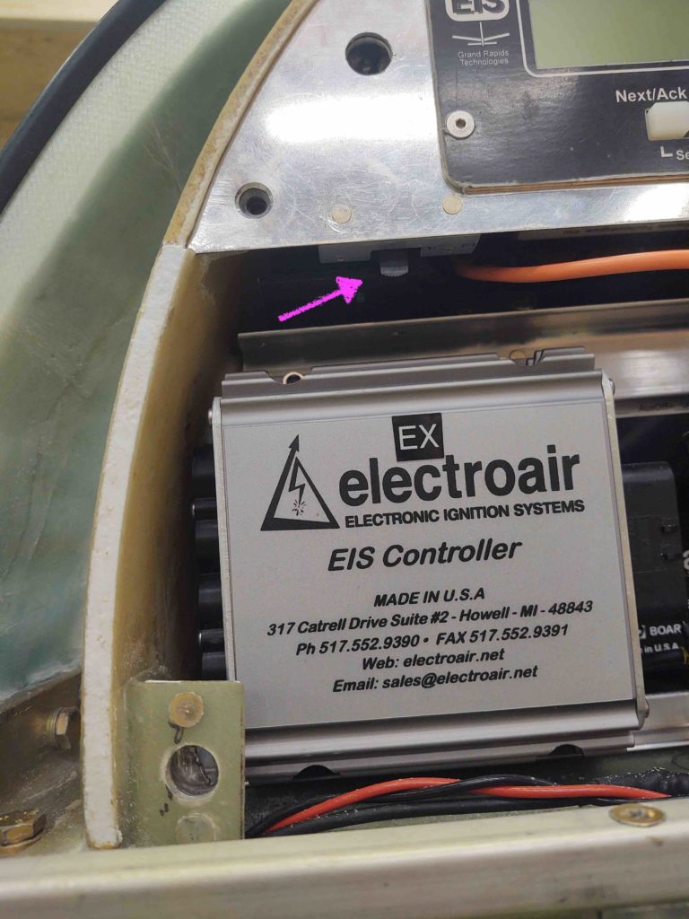
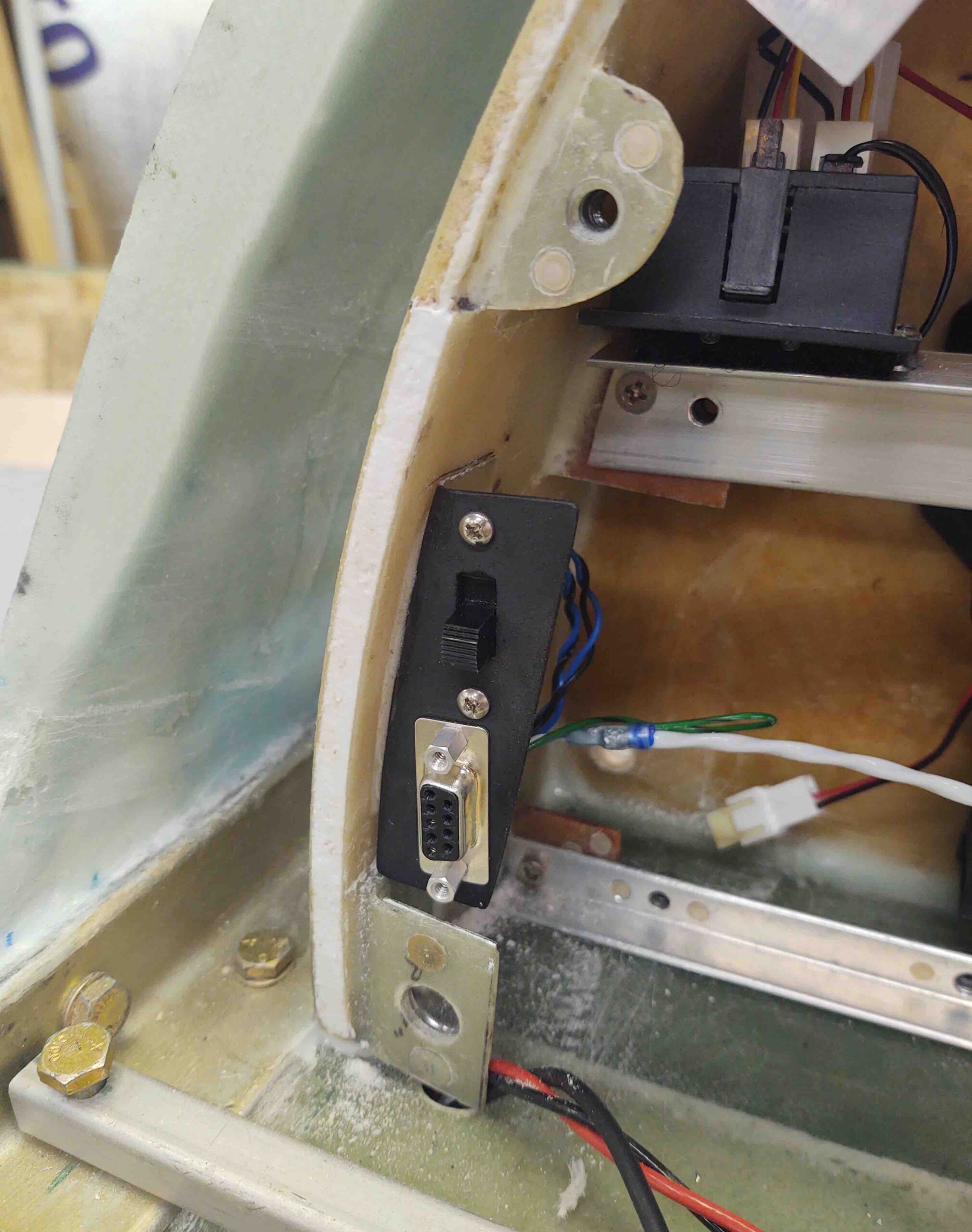
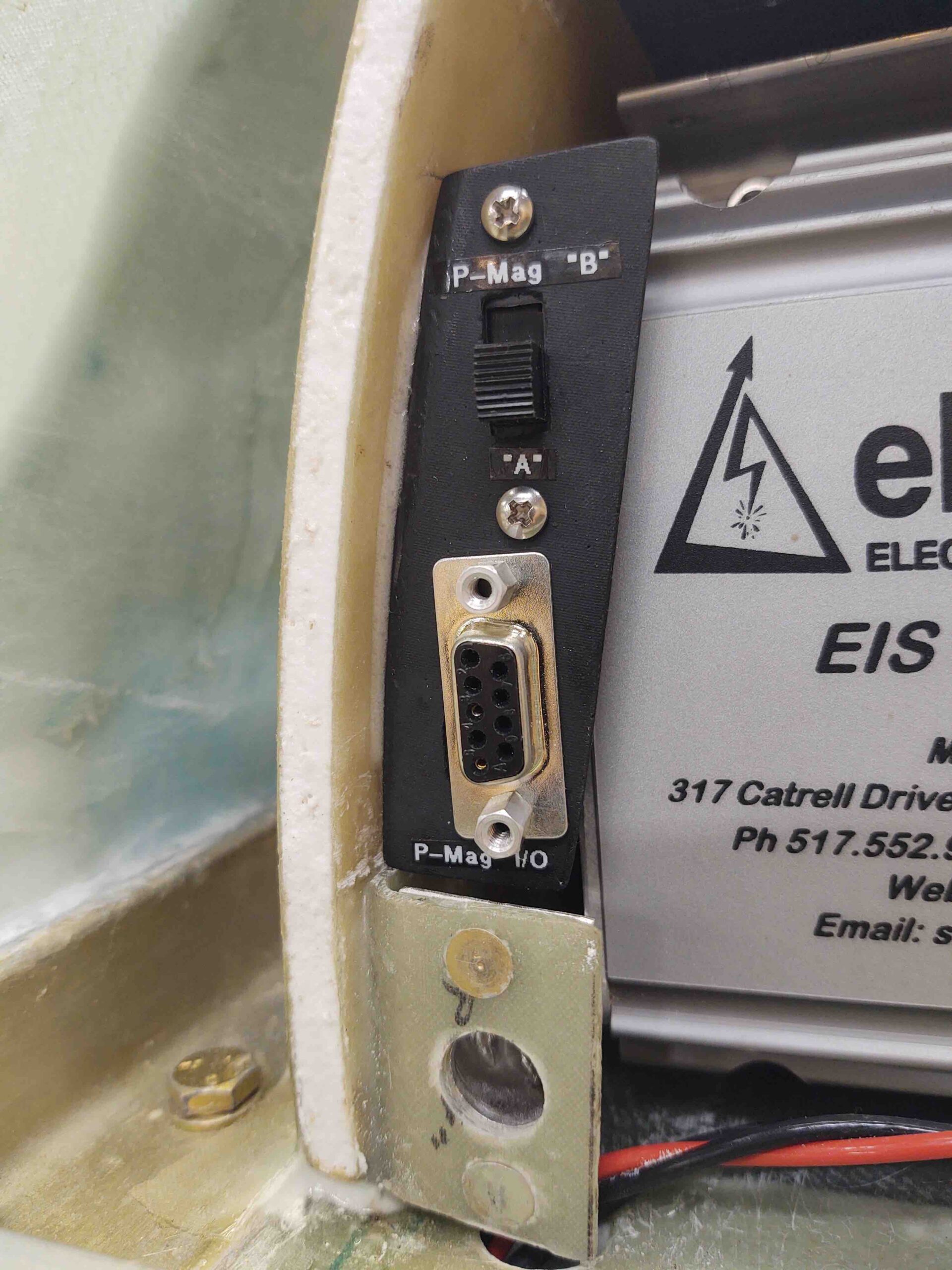
I then set my sights on constructing the P-Mag’s Variable Timing Select (via a switch) and Data I/O (via serial data over a DB-9 connector) cable.
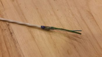
I focused on the engine mounted P-Mag unit side initially. This cable requires a 2-conductor shielded wire and added ground lead off the shielding, so I used a solder sleeve. I started by trimming back the outer insulation of the wire and removing the shielding except for the ~1/4″ that will get soldered up in the solder sleeve.
I then soldered a green/black pigtail in place with the solder sleeve and then trimmed the ground pigtail to length. I specifically ran the ground pigtail out the solder sleeve on the same side as the other wires since this will be in the engine compartment and I wanted to minimize any free wire vibration.
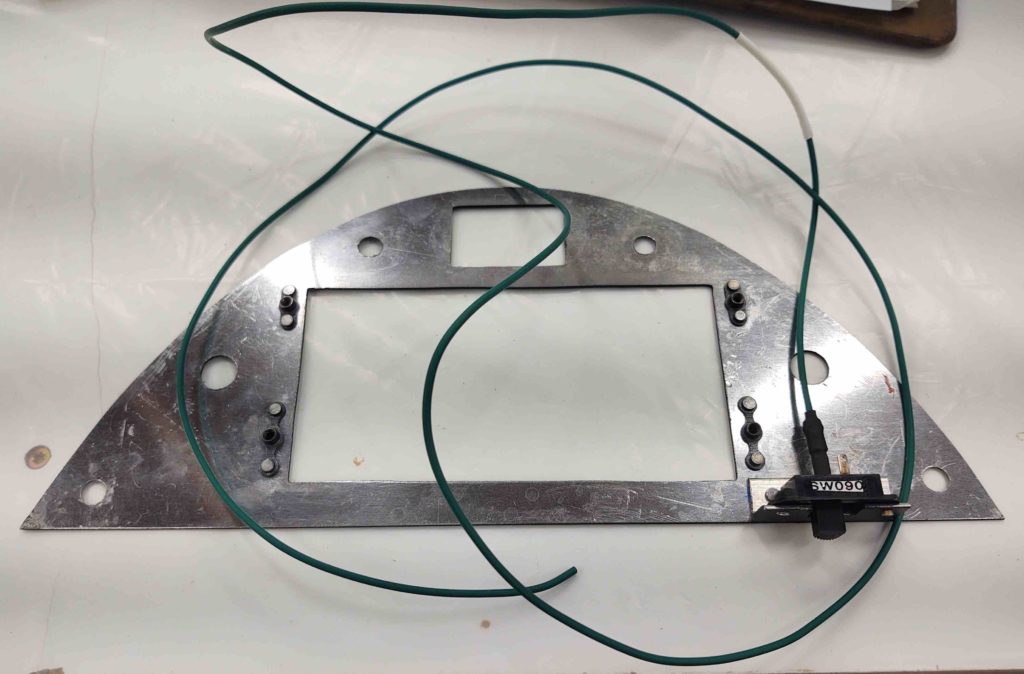
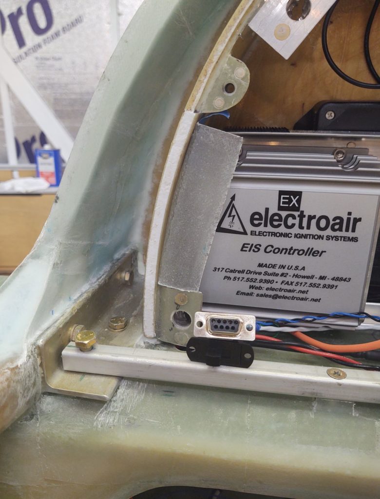
I then focused on the D-Deck/Turtleback side where both the switch (a dip style switch which I haven’t ordered yet) and the DB-9 female connector will be mounted just below the sub-face that will be visible when the GIB headrest panel is removed.
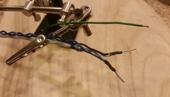
For the switch wires I tied in a 22 AWG blue and black twisted pair that was reclaimed from one of the trimmed Trio autopilot wiring harness leads by splicing them to the two leads from the shielded cable.
I then terminated the 2 shielded cable wires and the ground wire with D-Sub sockets and popped them into the 9 pin D-Sub connector.
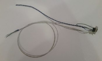
Below is the mostly completed P-Mag Variable Timing Select and Data I/O cable. The timing switch will allow me to change the timing curve from an “A” power curve to a “B” power curve in a scenario where let’s say I’m stuck in the middle of Wyoming and all they have is leaded auto fuel. It allows me to essentially suppress the spark timing on the engine to allow for lower grade fuel without subjecting the engine to the same power curve used with regular 100LL fuel.
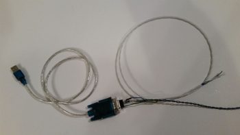
As you can see here, the 9-pin D-Sub connector allows me to connect up a laptop running E-Mag’s Interactive Control and Display (EICAD) program to view and tweak settings on the P-Mag electronic ignition unit.
If your interested in what exactly EICAD does, here is a little info page I snagged from the EMagair.com site:
I also awaited word that my Superior cold air intake sump arrived AERO Engines up in Winchester, VA so that I could finish the engine build.
•••
30 January 2018 — I put the finishing touches on hopefully what will be the last major revision of my electrical system. Specifically, my starting and charging system…. or perhaps let’s say a focus on the big yellow power cable running down the sidewall.
As I mentioned before, I had done an assessment of the incident involving Brian DeFord’s Cozy IV. That led me to entertain the idea of placing the Starter contactor on the cold/forward side of the firewall. Which I then posited the idea of doing so on Bob Nuckolls’ AeroElectric Connection forum –again, Bob, et al, never stated exactly why it SHOULDN’T be done but Bob was clearly not a fan of moving the starter contactor / solenoid off the firewall. Moreover, I discovered via back channels that a lot of canards are in fact configured with this contactor mounted on the cold side of the firewall.
More on the starter contactor wiring configuration in a bit.
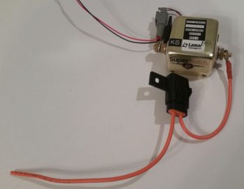
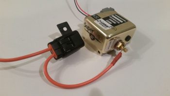
Having just wired the “Starter ON” warning lead that hangs off the Lamar solid state “Superswitch” that I am using for my starting contactor, I realized that I had been remiss all these years in actually ops/function checking this device to see if it was serviceable (obviously I assumed it was good since I bought it new from Aircraft Spruce…. that was years ago and they stopped selling them since probably around early 2012). But we all know what happens when we assume eh?
Well, there are two distinct features of a SOLID STATE contactor that make it challenging to ops check. I was aware of the first challenge, which is clearly stated in the nomenclature of this device: “Solid State” … otherwise better characterized as NO moving parts. Unlike the definitive “click” of a mechanical relay, or the “clunk” of a large relay/contactor/solenoid, this guy is quiet (also, for the record, much more “electrical quiet” when it comes to (not) generating unwanted noise). Clearly you simply can’t actuate and listen for a good ops function.
The second challenge was one that I wasn’t aware of until I was researching how overcome challenge #1. Apparently you can’t function a solid state relay unless the primary power connectors that carry a load are connected to power, since it “steals” some of this power to actuate the switching function. I tried it with an LED/470 Ohm resistor combo connected to both a 9v, then 12v, battery…. nothing.
Uh-oh, had my failure to do all this early on soon after I received shipment of this device cost me a pretty penny?! (This cost about 3-4 times as much as a “standard” B&C starter contactor). I contacted Lamar, knowing that this item had been out production for quite some time.
As often is the case, an aircraft manufacturer will use a specific part, here it was Lancair using this Superswitch for their Columbia Aircraft (and possibly other Lancair designs). I’m guessing that the most likely scenario is that when the Division of Lancair building the Columbia sold the line to Cessna to be reintroduced as the Corvalis, this specific part was no longer part of Cessna’s electrical system design so the inventory was left to die on the vine, dwindling its way into near-extinction, although reports from those who have used this contactor are normally overwhelmingly positive (I’m clearly extrapolating here on the “what happened” scenario, since I’ve experienced this same type of thing on a couple other aircraft parts ACS sold which then vanished from existence once ACS’s inventory sold out).
I spoke with Jim at Lamar who stated that not only does there have to be a load sensed on the primary switched power connectors (the big lugs), but that the current needed to be over an amp. While I was looking for something that would require an amp to drive it, Jim stated to simply hook up the leads of a 12V battery to the posts, and that the Superswitch itself would serve as the load. Ok, good to go. He seemed rather uninterested in dealing with an obscure, obsolete part that they had produced probably well over a decade ago, so he excused himself off the phone.
Then it hit me . . . how will I know if it works or not since I will have no indication once the control switch is activated that the large terminal switches have closed? (back to challenge #1, this thing is SILENT!). Ahh, I’ll do something that I rarely do with my Fluke multimeter, I’ll use it as an ammeter!
Well, with my thinking I didn’t want to blow up my Fluke, once I connected my test leads in series into the power circuit on the main terminals (again, just using a 12V battery), I set the ammeter function on the 10 Amp range. I then added 12V power to the Superswitch’s control (coil) leads. Nothing. Hmmm, ok . . . I then set the ammeter on the 400 mA range and again added power to the Superswitch’s control leads, upon which I got the very slightest of jump in amperage showing up on the Fluke. I tried it a number of times, all with repeatable and consistent readings. Hmmm… I still knew not a lot and I wasn’t sure what the data was telling me.
I emailed the results of my little test to Jim, who immediately emailed back that my ops check was in fact successful and the unit appeared to be working fine. Wow, probably the most anti-climactic ops function test I’ve ever performed on a piece of equipment! But, I was happy to confirm that it is working.
Check that off the list.
Ok, back to both the new mounting location and wiring schema of my freshly ops tested Lamar starter contactor.
I noted that there had been a lot of chatter from both Canardians and tractor bubbas about my “moving the starter contactor” proposal. Bob and tractor guys were not very welcome to the idea, while I again found out that a TON of canards are configured with the starter contactor on the cold side of the firewall.
First off, in a very un-theatrical or suspenseful way, I will simply state that I am NOT moving my starter contactor to the cold side of the firewall. So this new design below that I discussed a couple of posts back is OUT… persona non-gratis!
Why? Well, read on . . .
One builder/flier, specifically, sent me an email that while his proposed starting circuit design interested me, I admittedly didn’t place it on my list of viable options since my goal was to simply the move the starter contactor off the hot side of the firewall and into the Hell Hole. This builder, Steve Stearns, shared with me that he simply went against the conventional wisdom of Bob Nuckolls’ Aeroelectric Connection Z-13/8 architecture, that has the starter and alternator B lead sharing the big positive power cable running down the Long-EZ fuselage. Bob’s laudable goal in his dual use design was of course to save weight, and I’ll posit based on the convention that we simply place starter contactors on the firewall, because that’s where they belong.
What Steve had done was separate those 2 cables back out into their respective functions so that the big cable handled the starting and another 8 AWG cable was added back into the mix specifically to serve as the alternator’s B lead (okay, my aversion to adding A) a thing and B) weight, kicked in and although <clearly> I assessed Steve’s new proposed architecture, I’ll admit honestly that my paradigms were quite in play!).
To take it one step further, Steve proposed moving the starter contactor off the firewall, just as I was looking to do, but not to the Hell Hole …. oh, no . . . go big or go home here folks: Steve’s crazy notion was to move the damn thing ALL THE WAY UP TO THE NOSE! (Whaaa…?!??!?!) What this does is simple: it removes the big long fat high current cable that is always hot when the master switch is ON so that the segment of “exposed” always hot cable is literally 6 inches long, not 10 feet long. Hmmmm….
But add another wire? I dunno… sounds too against the grain. I mean the “massive” amount of weight and all. But 8 AWG? “Well, how much does that weigh?” I asked myself out of curiosity. So I weighed 4 feet of 8 AWG wire, and it came in at almost exactly a quarter of a pound. 4 oz?! “Ok, how much would I need?” I again asked myself. So I went to the fuselage and measured just a little shy of 11 feet. But, let’s make it EZ and round that figure up to 12. So, 0.75 lb is the net increase in weight. Hmmm, really? My paradigm was for a big 2-4 AWG welding cable, which as we all know is HEAVY. But, 8 AWG Tefzel comparatively is obviously much less hefty.
Hmmm?
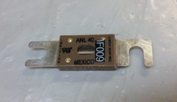
Then there was the weight of the stuff that would inherently get moved forward in this design . . . much farther forward! Ok, so I would move the Starter Contactor and its associated “Starter On” warning lead, and the ANL 40A fuse link (which needs to be on the distant end from the alternator) up to the nose battery compartment. “Well, how much do all those weigh?” I again ask myself . . . 0.764 lb.
Ok, let’s recap:
- “Always hot” cable reduced from ~10 feet to ~6 inches (buried in the nose)
- Starter gets dedicated 4 AWG circuit (actually 4-CCA, so more like ~3 AWG)
- Alternator gets dedicated 8 AWG B lead, no sharing or exposed to starting current
- Less than 3/4 pound net weight added (~1 ft aft of CG, the rest forward of CG)
- Around 3/4 pound moved off firewall and up to nose (nearly farthest point forward)
The more I deconstructed this architecture and actually looked at the real numbers, the more and more I really liked it. I spent a couple days researching and talking to some very smart electrical engineer types with aviation background, and none of them found any negative aspects to this design. My overarching concern, intuitively, was having the starter contactor so far removed from the starter. However, cognitively, and backed by the data I found and discussions I had, was that the starter contactor is really just a big switch allowing current to flow from Battery >> Master Contactor >> to Starter…. so there didn’t seem to be anything other than convention proving to be a roadblock to this working.
First off, here’s a more refined diagram depicting my initial chicken-scratchings on how all this is situated.
Secondly, I pulled the trigger on this design. I ordered a few more cable terminals and 12 feet more of 8 AWG wire that will enable me to incorporate this new starting and electrical system charging architecture into my Long-EZ. With the actual added weight most likely around 0.6 lb, and 80-90% of it all situated forward of the CG, as well as cleaning up respective starter and alternator B lead circuits so A goes to A and B goes to B, I am excited that this is a very clean and optimized design with little added weight. In addition it really cleans up the firewall, and the Hell Hole, and is much more refined of an architecture for just a slight weight penalty.
I would like to say a special thanks to Steve Stearns for taking the time to communicate and share this design with me (thanks Steve!).
I should also note that with such a significant design change, it took me well over 3 hours tonight to update the 2 main electrical diagrams I have that depict this architecture.
•••
1 February 2018 — I’d like to report something that is of minor note to be sure, but a to-do item checked off my list nonetheless: I purchased my fuel flow codes from GRT that allows me to integrate my FT-60 Red Cube fuel flow meter with the GRT EIS4000. This means that I have one minor non-GRT Hall Effect sensor to purchase to enable a more traditional battery charge/discharge ammeter (only with REAL #’s) at which point all my array of EIS/EFIS feeding sensors will be in hand/configured.
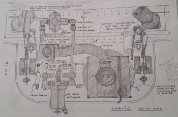
Looking at my firewall components wiring and component placement planning, I then took a bit of time to re-read Section IIL of the plans to glean any good info from it that I could regarding the eventual engine install (a reminder: it’s still below freezing here weather-wise, so I’m still in non-shop work mode). I was looking at this page (below) and started playing around a bit and ended up graying out all the components on the original firewall diagram that WILL NOT be on mine. BTW, to be clear there are no “replacement items” for those grayed out below, they are simply removed. The closest to a swap out you could say is the in/out oil lines for the oil heat system.
One point of note planning wise, is that I relocated the main electrical cable firewall pass-thrus from the lower left corner (looking forward) of the firewall to the lower right, a bit below where the aileron control tube exits the firewall. This location minimizes/straightens the cable run lengths and keeps my firewall ground, starter, alternator B-lead and F-lead all within about an area around 4″ in diameter.
Also, I understand this is a rather campy, convoluted looking slide below, but it’s essentially just one of my notes’ pages that gives me all the pertinent info I need represented visually. As you can see, essentially I’ve pretty much figured out all my wire runs (initial plan anyway) both in the engine compartment itself and through the firewall.
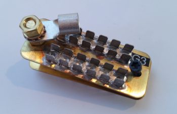
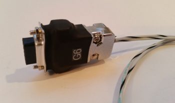
In addition to my electrical system shenanigans above, I also created a new ground bus “G6” for just the D-Deck/Turtleback area. It will be a 9-pin D-Sub connector that is connected by two (2x) 18AWG wires that run from the Hell Hole’s G3 ground connector (pictured below). This will provide me one simple ground point to contend with in the GIB headrest/Turtleback area and will keep me from having to run a fair number of separate ground wires down to the hell hole.
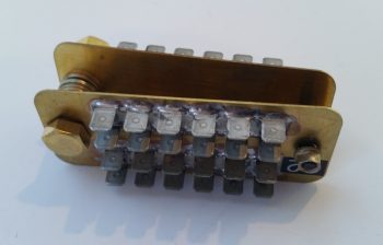
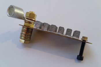
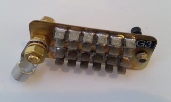
Moreover, I’m removing the firewall “forrest of tabs” ground connector on the firewall side and will use just the bolt since I have only two items on my engine that need ground wire connection points (Electroair coil and PMag). Below is the original B&C “forrest of tabs” firewall ground busses. The firewall ground bus identification is G2 while the Hell Hole ground bus identification is G3.
Here’s a shot showing the G2 firewall ground bus.
And the other side of this contraption, the G3 hell hole ground bus (with the terminal for the big yellow ground cable attached for inventory tracking).
As I stated above, since I only have 2 firewall component ground wires to contend with, I’m not putting that busy looking monstrosity back on the firewall to simply take up weight and space when it’s not needed. Here’s how it will look on the firewall (ok, if my bird were doing a full afterburner climb like an F-15…. ha!)
And one last shot of the G2 firewall ground bolt (by itself now) and the remaining G3 hell hole “forrest of tabs” ground bus.
•••
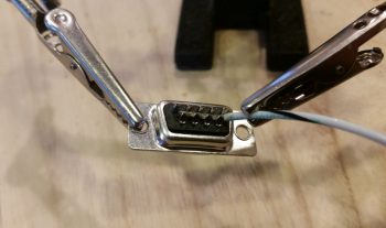
3 February 2018 — I started out today working on my D-Deck/Turtleback located G6 ground bus that consists of a 9-pin D-Sub connector soldered to two (2x) 18 AWG wires which will in turn be connected to the G3 ground bus in the Hell Hole.
I stripped off a bit more insulator than normal on the 18 AWG wires since I wanted them to fill in the channel on the aft side of the female DB9 connector, which is configured with solder terminals.
I then soldered the two 18 AWG wires in place. You may note what looks like a bit of a cold solder weld in the pic below. Not to worry, I saw it as well and reheated the joint and slathered on some more solder.
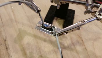
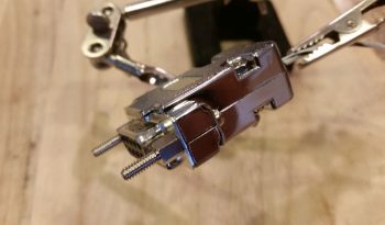
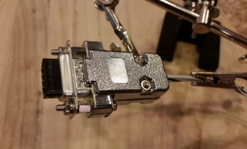
I then encapsulated the two 18 AWG wires soldered to the female DB9 connector with a standard backshell. I then added two threaded standoffs to the face of the connector that would allow me to permanently mount the male connector.
Which I did here. In the same manner as my G5 Avionics ground bus, this simply allows me to terminate a wire with a D-Sub pin and then easily pop into this G6 ground bus.
I then added a bit of heat shrink over the mated D-Sub connectors and then labeled my new G6 ground bus.
Here’s a close-up shot of the new G6 ground connector that will serve all the components in the GIB headrest area. If it looks a bit chunky I have to admit it felt a bit hefty, but then when I weighed just the connector it was just under an ounce.
•••
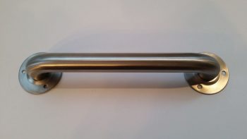
4 February 2018 — Today I started off by performing some slight of hand that, quite honestly, at this point & time I don’t remember quite how I found this out. I do remember the originator of this idea gave some specifics, which was basically purchasing a stainless steel bathtub handle that includes some requisite flanges that magically allows it to be turned into a firewall pass-thru for electrical wiring.
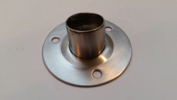
The trick is rather simple, extricate the amount of tube and flange from the handle grip section, and Voila, you’ve got yourself a mountable stainless steel firewall pass-thru with approximately 1.1″ ID.
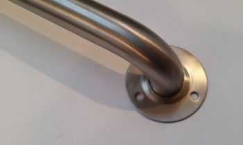 And here it is after I performed my magic (with a Dremel Tool cutoff wheel).
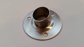 And another shot. As you can see, I wanted just enough were I could mount a length of fire sleeve around the outside of the tube and secure it with a hose clamp.
The next items on my list were to trim and terminate the ground wire to the EIS4000 and then power up the unit to enter in the fuel flow software enabling codes that I received from GRT the other day. I started by extricating the black ground wire from the EIS wiring harness bundle.
 I then trimmed the ground wire much shorter.
I then stripped the end and terminated it with a D-Sub pin. This is all an effort to mitigate the long ground wire runs to the Hell Hole from the D-Deck/GIB headrest area and consolidate all these grounds at the new G6 ground bus that I just constructed.
I then hooked up the EIS4000 to 12V power . . .
and then fired it up. I then proceeded to double check all the settings to ensure that they were zeroed out. When I hit the 2 separate screens that required the discreet codes from GRT to enable the fuel flow meter, I entered in the codes. I then did one more double check to ensure I got everything inputed correctly and then powered down the unit.
•••
7 February 2018 — Today I received my latest order from Mouser, which included my 3K Ohm 3 watt resistor required for the SD-8 Bridge Rectifier ground lead. With my almost last component for the SD-8 on hand (now I need to order a DPDT relay). I then got to work installing it.
The first task was to simply crimp a red PIDG Fast-ON terminal to the end of the resistor.
I then soldered my 20 AWG ground wire to the remaining resistor leg.
And then covered all that with some heat shrink. And then terminated the other end with a D-Sub pin to enable connection to the new D-Deck G6 ground bus.
I then connected my latest wiring “feat” to the appropriate tab on the Bridge Rectifier.
Here’s another shot of the completed SD-8 Bridge Rectifier ground wire (this allows for self excitation of the SD-8 system . . . meaning that it can turn on without having to see voltage from the battery. And not anything else. . . sheesh!).
•••
20 February 2018 — Today was another heavy research day… I keep having new information serendipitously presented to me via FaceBook, etc. …. then I ask a question, discussions ensue, and I find myself trying to finalize various configurations on my build (not bad, but often not my intent). Today it was information that Chris Randall shared on FB about wiring up the EIS4000: essentially I’m separating out the EIS4000 power and ground wires to provide cleaner power to the unit itself in order to prevent any wonky sensor readings. I’m grateful for the information to be certain, but these little heading changes do eat up some time.
•••
22 February 2018 — I kicked myself for having submitted an order to Mouser for the new SD-8 DPDT relay but once again forgetting to order the cooling/exhaust fans that B&C highly recommends for the SD-8 voltage regulator. Since the finned/air cooled Electroair EI control unit is mere inches away from the SD-8 voltage regulator, not to mention the heat sinked SD-8 bridge rectifier, I decided to kill 3 birds with one small cooling fan attached to the side of the D-Deck/GIB headrest housing.
Well, this afternoon I ran an errand for a friend of mine who asked if I could pick up a FitBit at a local vendor for her daughter and ship it to them. Well, the place I went to pick it up was a huge computer parts warehouse which serendipitously had just the fans I needed to fit my requirements above.
As you probably surmised, the larger fan is for cooling with external air and the smaller fan is an exiting warmer air exhaust fan.
•••
2 March 2018 — Since I brought the engine back home to my shop, I’ve been doing a fair bit of mock engine component installs and taking note of what I’ll need on hand to finish the engine installation when the time comes.
After a test install of the alternator and starter, I was also able to measure and then order the appropriate alternator-to-starter support link (1.794″ version) from B&C Avionics.
•••
8 March 2018 — Today my ACS order was delivered …. the order included the somewhat pricey Lycoming bolt for the starter. Also note the B&C alternator-to-starter support link test install.
I also received the last of the input sensors for my EIS/EFIS system: the Crazed Pilot Hall Effect sensor that I’ll be using to provide a simple Ammeter function to show whether the battery is getting charging current, and how much it’s getting (either positive or negative flow). As I mentioned before, with this unit the sensor is easily attached to any cable with zip ties as compared to the donut style Hall Effect sensors that typically must be placed onto the cable prior to terminating both ends of the cable. In addition, this unit is 12V (5V version also available) so I can run it off of ship’s battery bus power vs. having to connect it to either the EIS4000 or my 12V-to-5V converter, the latter which is starting to fill up quickly with other components.
Finally, this unit is Bob Nuckolls approved as far as this odd style of Hall Effect sensor being viable for use to input data into our modern EFIS systems (again, 9V battery shown merely for size comparison).
•••
12 April 2018 — Today I focused on installing the B&C Firewall/Engine ground stud and forest of tabs inside the hell hole [the usual configuration for the firewall/engine ground stud and forest of tabs is to have a forest of tabs on each side of the firewall. However, since I only have two items that require ground on the hot side of the firewall, I forewent installing the forest of tabs on the aft side of the firewall]. Although I didn’t get a pic of it, the engine ground strap is temporarily secured on the engine side where I plan to mount it permanently, so the length I ordered for the braided engine ground strap is spot on.
On the hell hole side of the forest of tabs, I then installed the big yellow ground cable that runs the length of the firewall to the negative ground post on the battery.
I then spent the next hour or so drilling and mounting the big yellow power cable that runs from the starter contactor in the nose battery compartment to the starter through a stainless steel firewall pass-thru. Inboard of the starter cable, I then drilled and mounted a Blue Sea connector for the Alternator’s B-lead that also heads up to the nose battery compartment.
Although this pic is a bit fuzzy, here is a final view of the firewall configuration tasks that I completed today. From the upper left hand corner you can see a hole drilled for the Oil Heat oil return line to the engine oil sump. Slightly lower and to the right of that is the main fuel line that feeds the engine driven fuel pump. Towards the middle is the #10 (3/16″) screw that I floxed into the hell hole as a mounting stud for the fuel filter’s Adel clamp. Then of course is the electrical firewall pass-thru package, starting from the left with the Blue Sea fitting for the Alternator’s B-Lead, a stainless steel firewall pass-thru with the starter power cable running through it, and then the engine grounding strap that connects to the the firewall ground stud that is opposite the forest of tabs inside the hell hole.
In the pic below I added in the Alternator’s B-Lead which will be paired together with the big yellow starter cable as they both exit the engine compartment via the firewall.
Here’s a wide-angle shot of the major engine component electronics, with the big yellow power cable of the starter, the Alternator’s white B-Lead, and the connected engine grounding strap connected to the firewall ground bolt.
Here’s bit closer shot of the starter and alternator power leads. Note that the Alternator’s B-Lead is terminated on the Alternator side but not yet at the Blue Sea firewall pass-thru. Also note that the starter lead cable is not terminated yet, and won’t be until I get the Fiberfrax and 6061 aluminum sheet affixed to the firewall.
Here’s the hell hole view of all my firewall-based shenanigans. Note that the fuel filter mounting screw is visible in-between the 2 yellow zip ties.
Here’s a little broader view specifically showing the Adel clamp that secures the pair of big yellow power cables.
•••
17 April 2018 — I started off today by making a decision on my electrical system, one that had been nagging me a bit in the back of my mind. The impetus for me making this decision today was a response by Bob Nuckolls on the Aeroelectric Connection forum that brought it all home for me. In a discussion on something else related to protecting wires with fuses and circuit breakers, Bob noted: “Recall that circuit protection is for WIRES . . . and that the protective device is installed as close as practical to the SOURCE of energy that puts the wire at risk.”
Thus, my ANL-40 fuse link is going back on the firewall, on the hell hole side. I’ll most likely use a piece of 1/8″ thick x 1/2″ wide copper to connect the forward (hell hole) stud of the Blue Sea terminal to one side of the ANL-40, then run the B-lead from the ANL-40 forward to the battery contactor (however, I’m leaving the option open to use 8 AWG cable and use this connection as the location for the GRT EIS Hall Effect sensor). This configuration will add a hair more weight aft, but puts better protection on the source of the B-Lead and cleans up my busy nose battery compartment a bit.
•••
19 April 2018 — Since I knew I was off my engine removal schedule by a day or two, while I awaited the fittings to finalize the fuel/oil lines I worked on something that I had wanted to get done as a self-perscribed prerequisite to drilling the 3-1/8″ hole in the firewall for the RAM air canister: mounting the ANL40 fuse link and base.
If you recall, after much consideration I modified my starter and charging circuit design by separating out the B-Lead into its own dedicated cable and by moving all the associated components to the nose-located battery compartment as such.
However, even though this configuration has been implemented successfully (reportedly), I was never too keen on the ANL40 being so far removed from the line it was protecting. I chalked it up to 2 things, made a mental note to assess it, and then pressed on. Those 2 things were that A) Again, its working in a real-world install, and B) 10 feet is not a huge distance to electrons that travel the speed of light.
However, as I pointed, Bob Nuckolls reminded me of a core principal that I was not following in regards to my ANL40 Fuse Link location when he stated, “Recall that circuit protection is for WIRES . . . and that the protective device is installed as close as practical to the SOURCE of energy that puts the wire at risk.”
Again, as a result, my ANL-40 fuse link was going back on the firewall, on the hell hole side. However, instead of employing a 1/8″ thick x 1/2″ wide copper strip, I went with my optional configuration and used an 8 AWG cable to connect the forward (hell hole) stud of the Blue Sea terminal to one side of the ANL40 with the GRT EIS HALL EFFECT SENSOR placed in-between, then ran the B-lead from the ANL40 forward to the battery contactor. Therefore, my new starting & charging circuit configuration looked like this:
My 2 goals for the day were to install both the ANL40 base, fuse link, etc. and the GRT EIS Hall Effect sensor.
I started by ginning up a phenolic nutplate assembly with the same #10 screw pattern as the ANL40 base. Since the fuse link sits in the middle of the 2 posts on the base, the only screws that can be used are countersunk screws. Since I was mounting the unit on the front face of the firewall I clearly could’t put nutplates on the aft firewall face, so I had to go with a in-Hell Hole surface mount solution.
Here’s the aft side of the ANL40 nutplate assembly.
And a couple shots of the nutplate assembly installed on the ANL40 mounting base.
To embed the nutplate assembly onto the forward firewall surface in the Hell Hole, I made a mounting pad for the ANL40 mounting base from 3/8″ PVC foam.
I then carefully carved out a notch for the nutplate assembly in the foam mounting pad.
Here’s a bottom shot of the foam mounting pad with the nutplate assembly installed.
I then used 3 plies of glass (BID/UNI/BID), prepregged, and glassed the ANL40 foam mounting pad with the nutplate assembly flocro’d into place (with all the typical pre-work: micro-ing foam, etc.). Again, the mounting pad was glassed onto the forward side of the firewall in the hell hole.
A few hours later I cleaned up the cured layup (yes, I used fast hardener) and test installed the 2 ANL40 base mounting screws. I also trimmed the glass overhanging the existing firewall electrical package component holes and redrilled the upper holes for the mounting screws.
I then mounted the ANL40 base into place with the 2 countersunk screws.
And remounted all the firewall electrical package components (again, except for the ANL40, these are all temp mounts until the Fiberfrax and 6061 aluminum firewall cover are in place). I uploaded both pics of this since they show a bit different viewing angles.
Being able to get a feel for the space between the Blue Sea B-Lead connector (it’s red) and the ANL40 base, I then got to work finalizing the GRT EIS Hall Effect sensor configuration. I trimmed the long 8 AWG wire and terminated the Blue Sea connector end with a 3/8″ terminal. I also labeled & trimmed the ground wire, then terminated it with a Fast-ON PIDG terminal.
I slipped on the white rubber boots, and Voila! Ready for install.
Since I’ve had the actual ANL40 fuse link for a number of years, there was a bit of tarnish on the metal blade connectors so I used a Scotchbrite pad and some white vinegar to clean them up a bit.
I then installed the ANL40 fuse link into its base, on top of the glassed-in foam mounting pad (with the embedded nutplate assembly) and then got busy connecting all the cables to their appropriate mounting lugs.
I also co-ran the red 14 AWG SD-8 backup Alternator power feed wire through the GRT EIS Hall Affect sensor a couple of passes (both the primary alternator B-Lead and the SD-8 backup power feed get passed through the Hall Effect sensor twice to place the readout scale on a 0-50 Amp scale vs a 0-100 Amp scale… the latter which I don’t need since my primary alternator only puts out 40 Amps max).
The route of the electrons is this: Alternator current runs via B-Lead to the firewall side of the Blue Sea pass-thru connector (red fitting), then on the inside of the Blue Sea pass-thru a cable runs to the right post (in pic below) of the ANL40 fuse link VIA 2 passes through the Hall Effect sensor donut. Then, from the ANL40 left post (again, as depicted in pic below) an 8 AWG B-Lead cable carries the current up to the nose, connecting to the Master Battery Contactor (as depicted in my updated diagram way up there ↑).
Here’s a closer up shot of the installed ANL40 Fuse Link.
In addition, you can also note that I used a decent sized piece of heat shrink to seal and cinch up all the wiring going through and wrapped around the Hall Effect sensor donut. It may seem like the Hall Effect sensor is left to sway to-and-fro in the wind, but with the robust 8 AWG cable securing it in place, and the amount of force I had to apply to get both terminal ends in place (not excessive, but it’s tight) …. that puppy ain’t budging!
Another angled shot of the ANL40 fuse link for the alternator’s B-Lead feed and the GRT EIS Hall Effect sensor . . . plus note the additional “big” wire runs that are deemed big enough to hang out and traverse the fuselage with the big yellow cables.
And a final parting shot for the evening.
•••
21 April 2018 — Today was a day of lessons for the ‘ol Airdog here. First off, my buddy Dave B. asked me a question on this website regarding the use of an ANL type fuse link for the SD-8 backup alternator, and if I did use one was it located aft or in the nose? Wow, ok… probably a question I should have asked myself and a big oversight on my part.
As I saw it (after Dave’s prompting) the logic flows like this: I just moved the ANL40 fuse link on the B-Lead aft because the antagonist in my view was the main 40A alternator. I again based this off of Bob’s statement that the fuse should be closest to the offending power source. Ok, now the SD-8 backup alternator is in the back as well, but its 30A fuse –as spelled out specifically in the Z-13/8 system architecture– must be located within 6″ of the master contactor (in the nose). But why? The key I discovered is identifying the potential antagonistic power source, which I had done incorrectly.
I posted this question on the AeroElectric Connection forum and almost immediately got a response: the alternators are not the main point of concern since if the wire leads from them are rated at the max current they can produce, then the wire will be safe. However, the battery is a source of potentially hundreds of errant amps hitting the wire if it decides to go a little haywire.
Thus, I had picked the wrong villain, and as Sun Tsu says, “Know your enemy.” I did not. This of course meant that my action to move the ANL40 fuse link aft was all for naught, and moreover, incorrect. Lesson learned. So, my latest diagram should be depicted as such:
And my new configuration for the ANL40 is nothing more than my previous CORRECT depiction, shown here. Ahh, the circle of life…. ha!
In a subsequent discussion Dave and I discussed alternators going haywire, and as a point of note I’ll state that alternators such as the ones B&C sells have built-in OverVoltage protection to guard against runaway alternator current causing damage.
•••
23 April 2018 — Today I took a few minutes to remove the ANL40 from the front side of the firewall in the hell hole and put it back upstairs. It will get installed later when I finish up the electrical components install in the nose.
•••
16 August 2020 — Today I set my sights on starter contactor inside the battery compartment. I assembled the starter contactor (attached to its 3D-printed mount), the battery contactor, and the battery. I mounted them in place (repurposing one cable clamp hardpoint for the starter contactor) and then assessed cable runs and configurations to ensure all would fit.
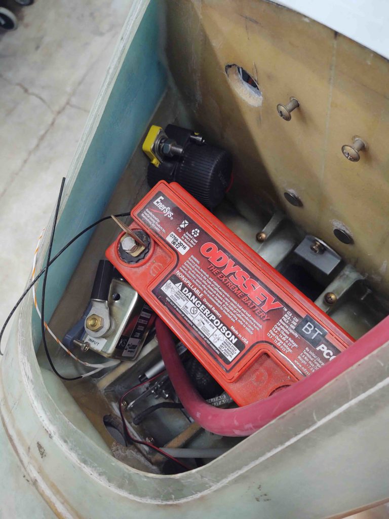
After figuring out the big cable runs, I then zeroed in the final position of the starter contactor (I also dialed in the position of the ANL40 alternator fuse bracket — not shown).
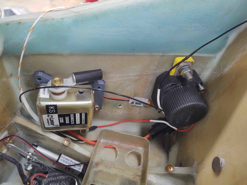
I drilled holes for the starter contactor mount bolts, prepped some RivNuts and floxed them into place on the front right sidewall of the battery compartment. The wood strip wedged into place and black steel part of a clamp are holding it all tightly into place as it cures.
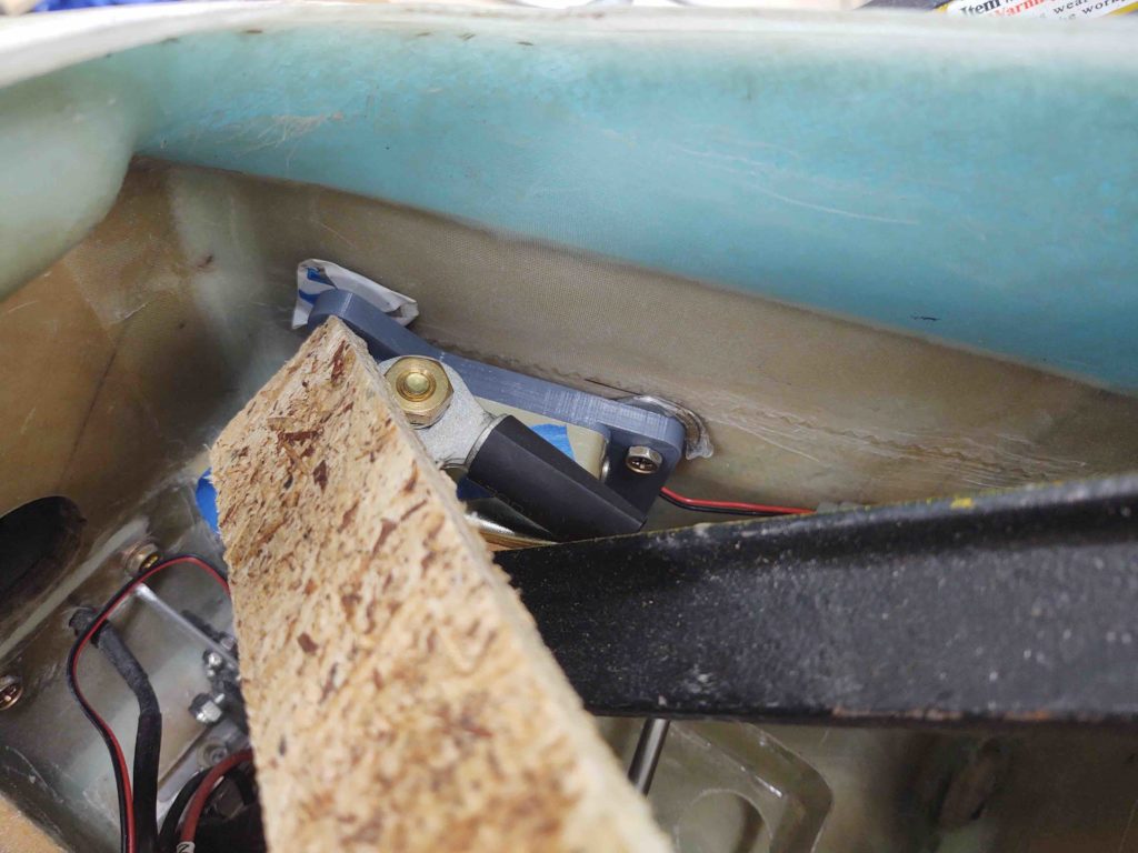
•••
17 August 2020 — Today I got a couple of electrical components installed, and as benign as that seems, anything mounted and placed (typically) is another item off the list for mounting, and one less decision that has to be made (admittedly, this is mounting #2 for the ANL40 fuse device… previously mounted in the Hell Hole).
Since I am once again using a S704-1 relay to control the SD-8 straight power feed to the E-Bus (I had removed it on the advice of Bob Nuckolls when he reviewed my electrical system architecture), since it is now back in play with this new E-Bus feed schema.
So I needed to mount this relay for the distinct purpose here that I’ll then be mounting the ANL40 fuse base on the front side of the Napster bulkhead close to opposite the position of this relay, this relay getting mounted is a prerequisite task to then mounting the ANL40 base… since screw clearances through the bulkhead can be maintained.
As you can see below, I then proceeded to drill & countersink (front side of bulkhead) the required holes and then mount the S704-1 relay.
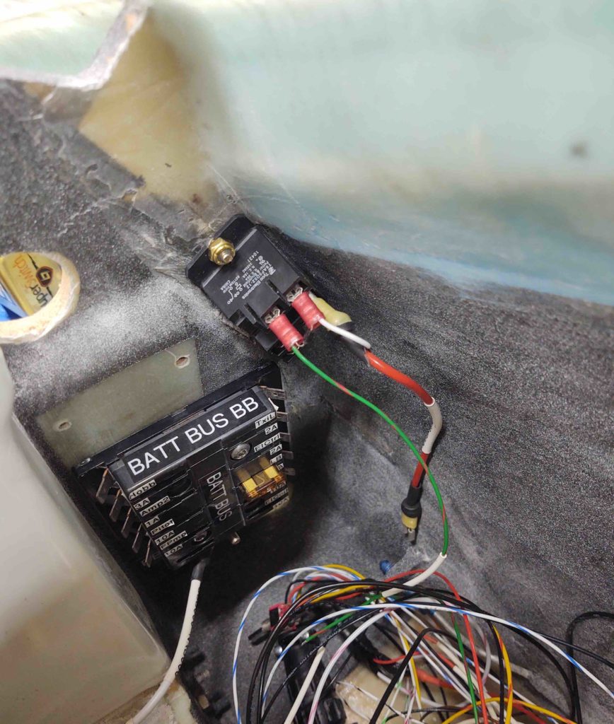
With the E-Bus feed relay mounted in place, I then mounted the ANL40 fuse base on the front side of the Napster bulkhead while ensuring its mounting screws missed the components on the back side of the bulkhead.
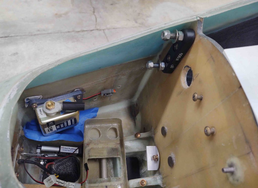
Here we have the Starter Contactor installed. The embedded RivNut bolt hard points came out nicely and I can check this component off the list as positioned and installed.
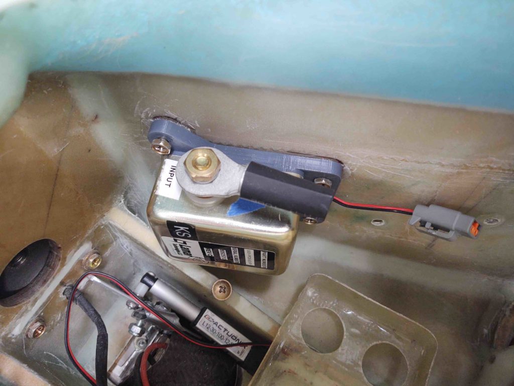
•••
22 August 2020 — Today I made up a power cable {yellow} for the feed between the battery contactor (on right) and the starter contactor (on left). I also reused the old 8 AWG wire feed to connect the battery contactor to the IF009 ANL40 current limiter (actually, I also lopped off about 1/4″ off the bolt studs on the IF009 to allow me to better get the white boot in place).
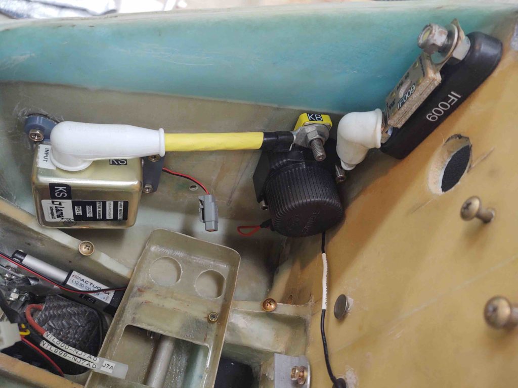
•••
25 August 2020 — Today I worked on the D-deck/Turtledeck/GIB headrest.
I have 2 slide switches and one D-Sub connector to install, to allow me somewhat easy access to them. One of the slide switches and the D-Sub connector are for the P-Mag EI.
The other slide switch I’ve installed here (actually just the switch bracket at this point), which controls the on/off for the Electroair electronic ignition manifold pressure (MAP) signal. Having this switch can be very useful for troubleshooting potential EIS issues, so I installed it onto the upper D-deck faceplate.
Here’s a final shote of the upper D-deck faceplate before it goes in for paint . . .
I then installed the actual Electroair electronic ignition manifold pressure (MAP) signal switch [sw090] onto its bracket.
And here’s the new look, with functioning switch in place.
•••
27 August 2020 — To best describe what I’m doing here on this first task, I’ll go in reverse chronological order starting with the glassed bracket, and show you what it’s for before I show you how I ginned it up.
First, the P-Mag Electronic Ignition has the option to select an “A” or “B” timing curve. In reality this will probably never get used, but I’d rather have it wired up and at the ready than needing it and not having it available (or worse, doing a field mod to wire it up).
Next, the P-Mag also has a serial interface to the unit via a DB-9 connector for selecting variable timing, data I/O, etc. Again, better to have it ready to go (IMO) than needing it and not having it installed.
So my current task is all about making a bracket to mount the P-Mag switch and DB-9 connector. In my idealized world all these would have been on the D-Deck’s upper interior faceplate (that I just painted black) but alas, putting them up there space-wise and difficulty-wise is too much hassle for these things. So I decided to put them down in the lower RH corner (left if facing aft).
This is the end result of my glassing effort, still to be trimmed to final shape/configuration.
Here’s how the bracket looked in raw form after I pulled it off the mold. Note the curved “top” edge which matches the curve of the interior side of the D-Deck/Turtledeck/GIB headrest.
And here we have the bracket just after I glassed it, with 3 plies of scrap BID. I peel plied the front face (top here) and the curved mating face (side here) to get a jump on cleaning it up for mounting in the D-Deck.
Here’s the form I made with scrap cardboard: flat on top for the front face and curved on the side to somewhat match the interior curve of the D-Deck/Turtledeck/GIB headrest.
•••
29 August 2020 — Today I worked on the D-Deck mounted P-Mag switch and D-sub connector bracket. I drilled out the screw and center body mounting holes for each (yes, once again I went a little wide on the D-Sub center hole… seems to be one my things currently!). Once the components were in place I then trimmed the top, bottom and inboard edge of the bracket.
Here it is mocked up in place.
I then disassembled the P-Mag switch/D-Sub mounting bracket and painted it.
I decided instead of floxing the P-Mag switch/D-Sub bracket onto the interior D-Deck wall, that I will simply use silicone RTV. That way if I ever need to remove it for any reason, it will come off in easier fashion.
To prep for mounting the bracket, I removed the Electroair EIS control unit.
And then mocked up the painted bracket with the switch and D-Sub installed again. This is NOT RTV’d to the inside D-Deck wall yet…. since it was late and I still need to find my silicone RTV!
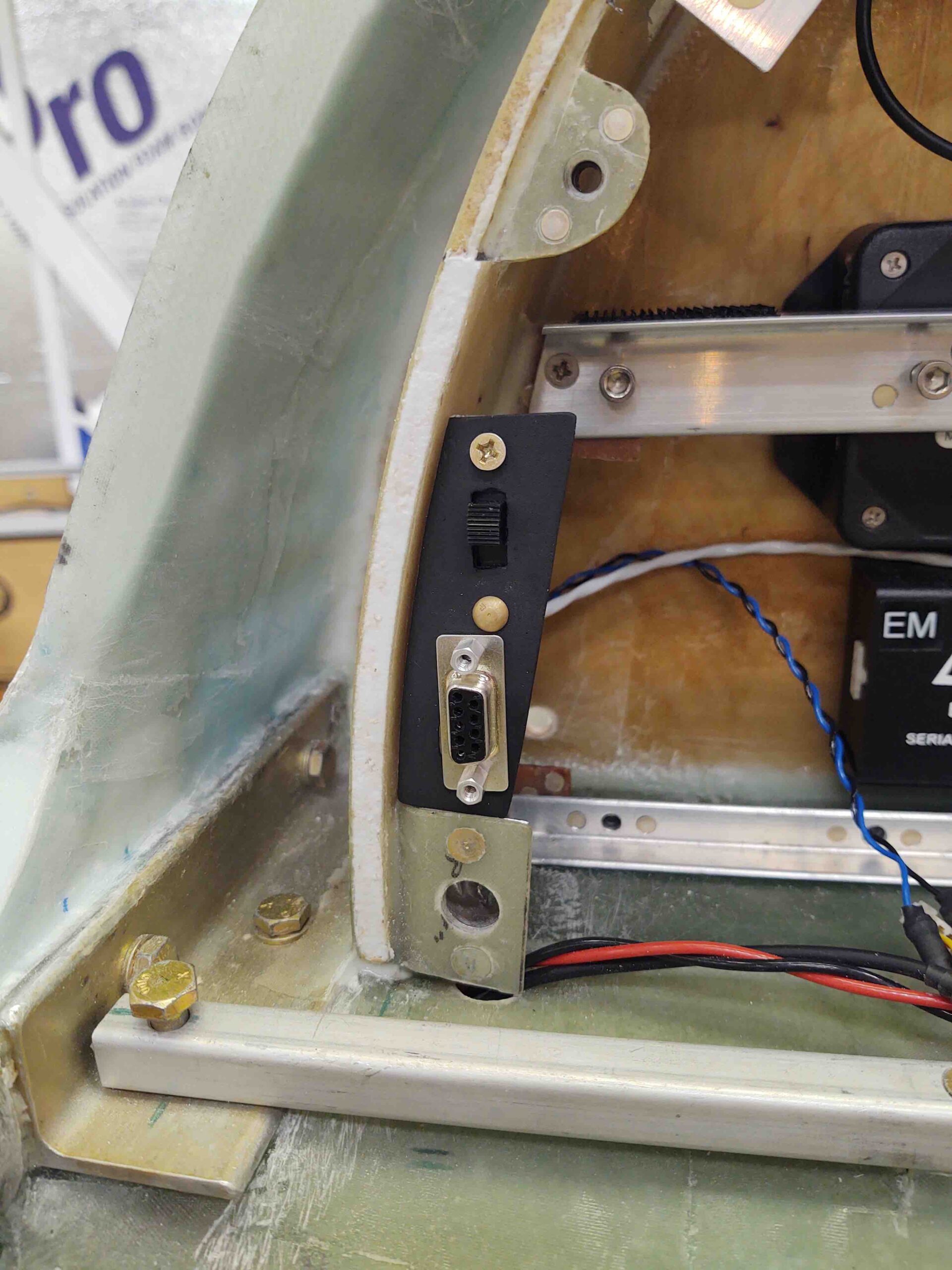
•••
31 August 2020 — The first thing out of the gate was I rounded up a tube of silicone RTV. After the final install on the P-Mag switch and D-Sub connector into the bracket, I then applied the silicone RTV and clamped the P-Mag switch and D-Sub bracket to the right interior sidewall of the D-Deck/GIB headrest.
Also after a few hours I check the P-Mag switch/D-Sub bracket’s progress… with staying mounted inside the D-Deck. Hmmm, not good! The silicone RTV was an abject failure, so in the trash it went. Must be too old.
Ironically, I then tried an opened 2-year old tube of Harbor Freight “5-minute” epoxy and it worked a treat… cured quickly and held it in place (obviously I chucked my bracket “removability” requirement out the window).
I then reinstalled the Electroair EIS Controller. Space is definitely tight, but it fit right in behind the newly installed P-Mag switch/D-Sub bracket.
As a point of note, this electrical component install puts me at about 2/3rds complete for all the electrical components (not wiring) for the entire plane. More importantly, this currently completes the installs (again, not wiring of course) of all the planned D-Deck components. Also, this overall total doesn’t include the actual panel components, which are pretty much a known quantity as well.
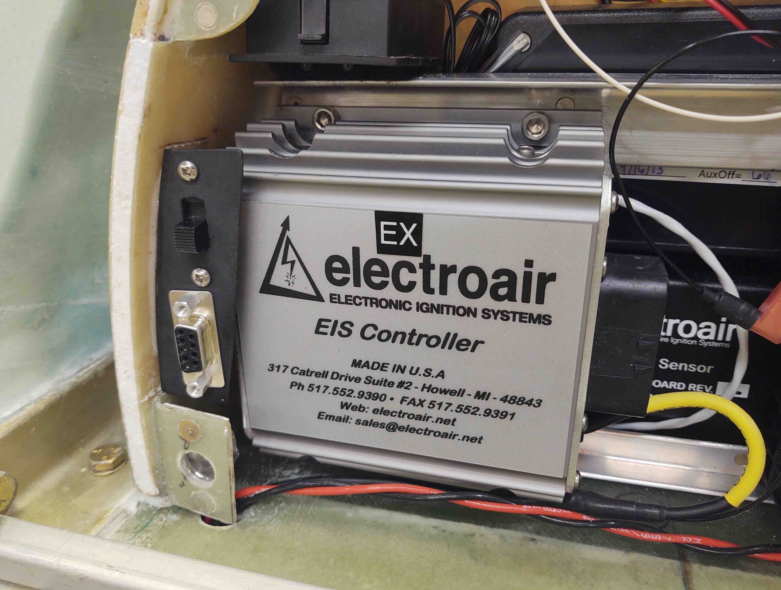
•••
1 September 2020 — I had a good discussion with both Trent and Brad at E-Mag Air concerning the “A” and “B” ignition timing curves and how that pertained to my specific engine (IOX-340S). They also gave me some very helpful tips on dialing in the timing curves when I start flying this bird.
For the switch to fit neatly astride the Electroair Electronic Ignition Controller box, I had to position it with the “A” power curve down. In fact, I had originally wanted to install the switch in a horizontal position so there would be no risk of it vibrating from one position to the other (these are simple slide switches). Well, as serendipity and/or luck would have it, my engine performs best on the non-standard “A” curve so the position was optimized for fitting into the D-Deck.
The normal A-B position of a “normal” switch was not captured though, with “A” probably and naturally being at the top position. Not wanting future Wade to screw this up, I figured it prudent to spend 5 minutes labeling the P-Mag ignition timing curve switch and D-Sub connector on this bracket.

