
Chapter 13/18 – Aft Nose/Avionics Cover Attach
This page covers the fitting and mounting of the Aft Nose/Avionics Cover with hinges and multiple attach points.
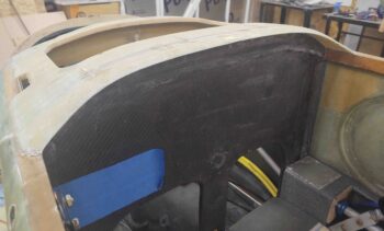
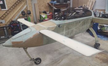
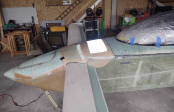
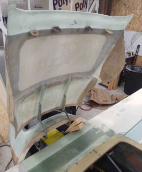
7 October 2020 — Today I finally cracked open the time capsule that is the aft nose/avionics cover. It took me a good half hour of gentle prying, coaxing, coercing and pleading for this thing to come off without any major damage!
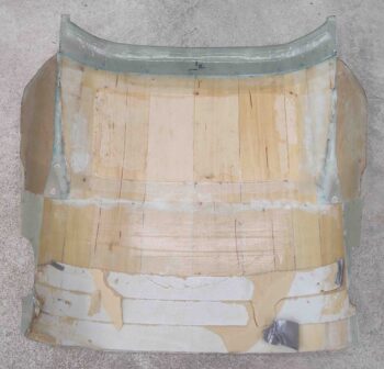
Here’s the nose side of these shenanigans. A site I haven’t seen in well over 2 years.
Another shot from the front.
I then started the seemingly unending task of removing tape and cleaning up the structure underneath the tape. This took a couple of hours.
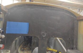
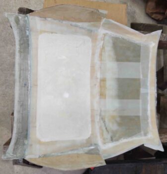
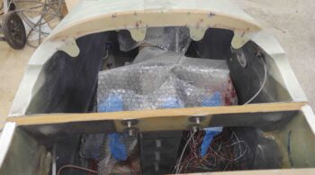
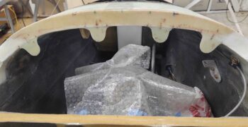
The protective plastic I had in place all during the glassing of the aft nose/avionics hatch sub-structure was still in place.
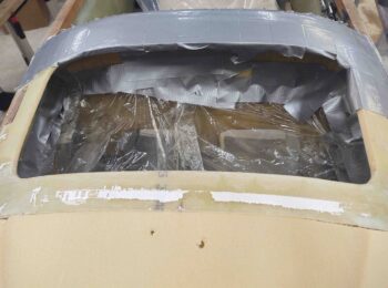
I removed the plastic and tape, and a few plies of old peel ply in the corners. I then gave the avionics bay a fairly thorough cleaning and vacuumed it out.
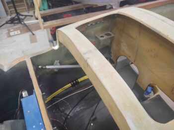
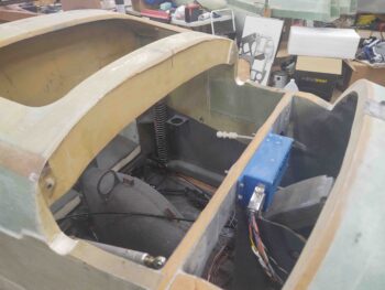
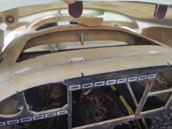
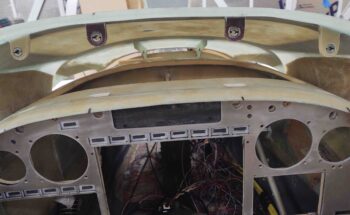
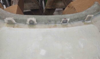
I grabbed this shot of the glare shield substructure from the top side.
And from below… not something normally visible when the nose cover & glare shield are in place.
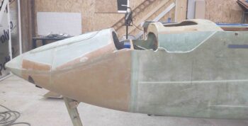
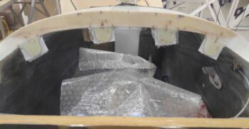
I also grabbed this side view shot showing the nose pocket where the canard will get mounted. I’ll be adding pour foam and glass in the forward lower corners of the pocket around and matching the lower forward contour of the canard.
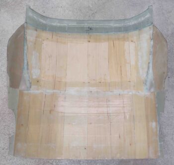
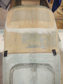
I then spent over 30 min cleaning up the underside of the aft nose/avionics cover. I cleaned off a bunch of dead glass and pulled a fair amount of peel ply. I’ll be giving it a very thorough sanding on the inside. Also, since I had to add an extra layer of wood on the top aft area of the cover for a better contour, I’ll remove a good portion of the lower (inside) layer of wood and then glass it for some weight reduction.
With the cover curing for over 2 years, it held its shape beautifully when I set it back in place. I’m pretty excited to see how this cover will look and function once the install is finished.
•••
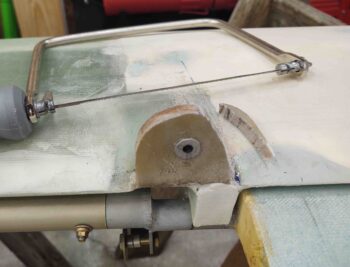
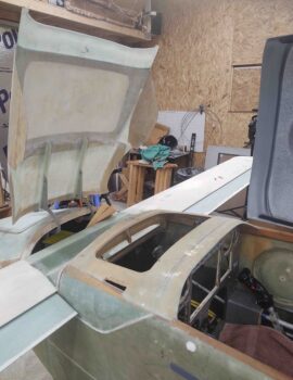
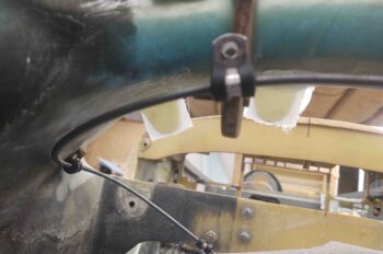
18 October 2020 — Today I popped the canard onto the fuselage to check out the fit and look with the upper nose completed. I quickly realized that when I had last installed the canard, the top nose area around the front end of the longerons was much fatter. With the new trimmed F28 outboard edges, it made the canard upper mounting tabs a bit wide on the outboard side. I marked the mounting tabs and then removed the canard.
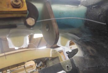
Well, in my fervent quest to get yet one more thing off the To-Do list tonight, I grabbed my coping saw and trimmed down the outboard excess on the upper canard mounting tabs. I’ll certainly have some sanding to do to finalize the shape and fit, but the major lifting on getting these to shape is done.
•••
19 October 2020 — Today I remounted the canard. I have to say I was pleased that all the bolts went in without much fuss.
As a point of note, this is the first time the canard has been installed on the plane since the upper nose and canopy are in place.
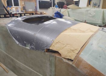
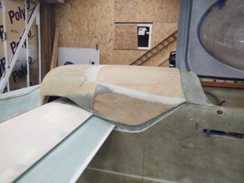
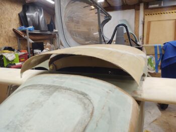
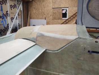
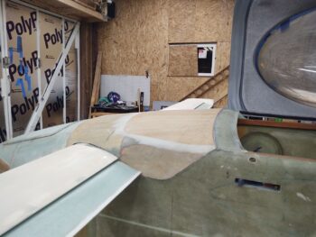
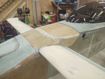
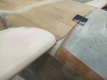
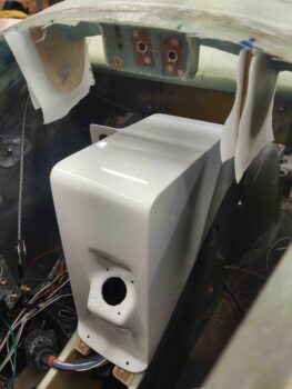
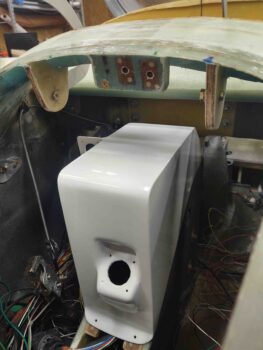
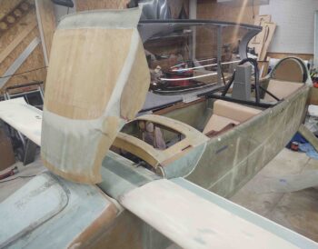
I then set the aft nose/avionics cover in place and got to work dialing it in to fit over the canard.
Here we have the untrimmed, unaltered aft nose/avionics cover.
You can see from the front there is quite a large gap.
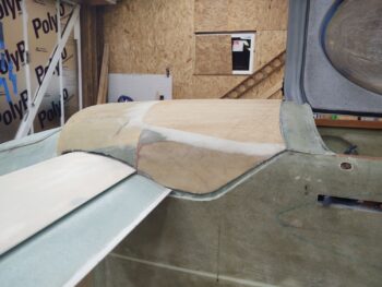
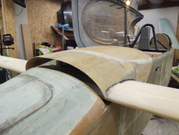
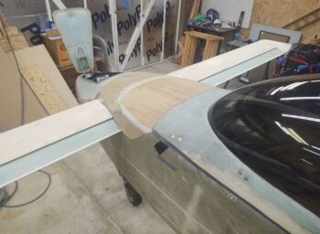
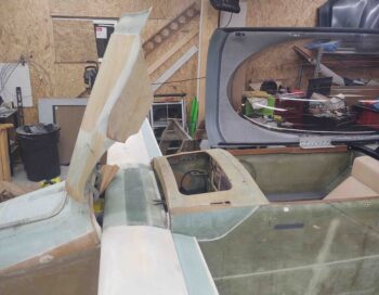
Here are the successive rounds of trimming I did. The pics below show 5 rounds, but I missed one set of pics, so it was actually 6 total rounds of trimming with the Fein saw.
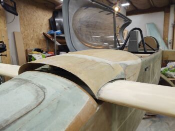
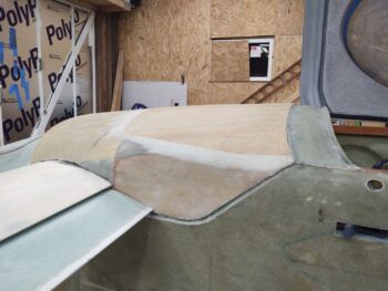
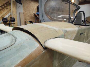
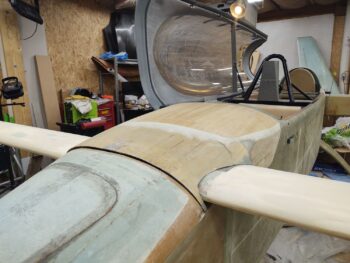
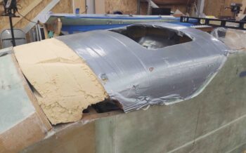
I ran out to grab a quick bite to eat, and when I returned I dialed in the rest of the aft nose/avionics cover fit onto the canard pretty much by hand. After another half hour I was very close.
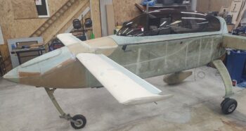
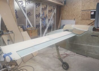
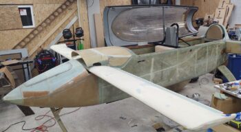
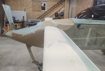
The following are just a bunch of pics of the canard installed for the first time with the nose, aft nose/avionics cover, and canopy all in place.
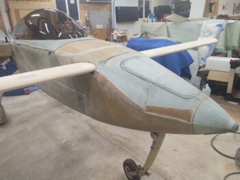
A side profile shot.
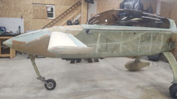
A couple more shots.
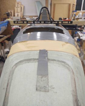
Some head-on nose shots.
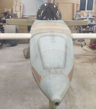
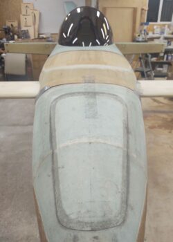
A closer in shot…
And a couple shots with the nose hatch open:
•••
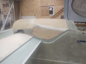
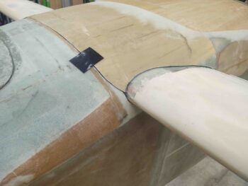
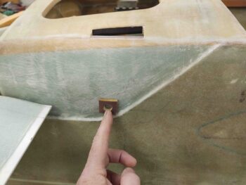
22 October 2020 — Today I slowly trimmed the front corners of the aft nose/avionics cover to fairly closely match the added fuselage corners in front of the canard LE.
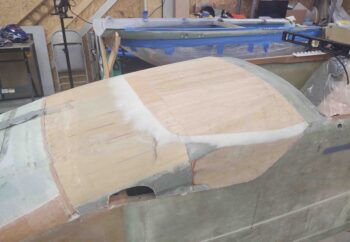
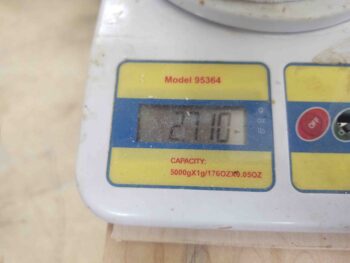
With my initial fitting task out of the way, it was now time to enroll the aft nose/avionics cover into “fat camp.” Yep, when I took this thing off it originally weighed in at just a hair under 4.1 lbs. Pretty chunky for a cover.
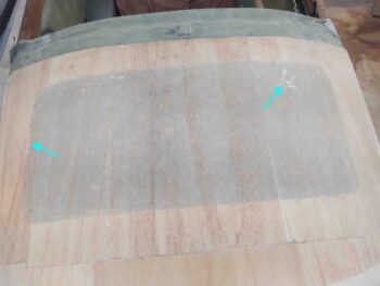
I hatched the areas that would be losing glass and wood, leaving only the exterior glass.
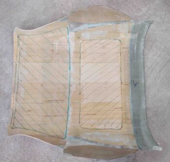
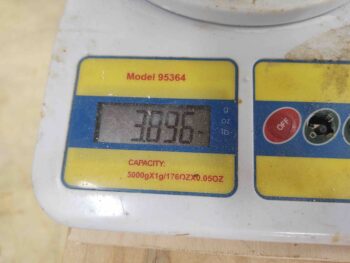
At the state of the cover above, it weighed in at 3.9 lbs.
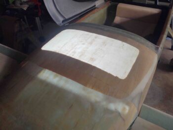
After 2+ hours of work, it looked like this. Note there’s still a decent sized chunk of glass and wood in the lower left corner –as situated in this pic– that still needs to come out.
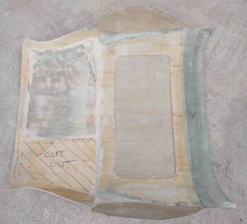
This is tough work, so my goal was to stop for the night when I removed a pound of weigh off the cover. Well, I exceeded that goal by a bit.
Removing the last segment that I ID’d for removal with the hatch marks will most likely drop the overall weight of the cover down below 2.5 lbs.
I was hoping for sub-2 lbs, but I don’t think it’s going to happen. Moreover, I’ll be adding some weight back in with a couple plies of glass and all the attachment tabs, hardware, etc. So the final weight of this cover will be in the ballpark of about 2.5 lbs, my best educated guess at this point.
I also had a few oopses and broke through the surface in around 4 spots. The glass in this area is particularly thin, maybe 2 plies thick, because it was the final top finish.
For fun I turned off most of the shop lights and chucked an LED work light into the avionics bay. Looks pretty cool with that thin cover glass.
•••
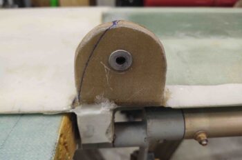
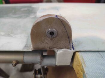
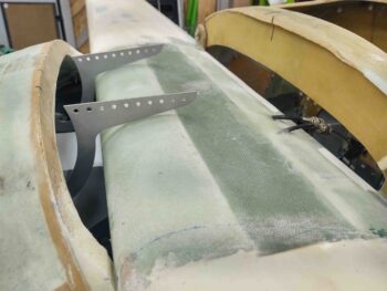
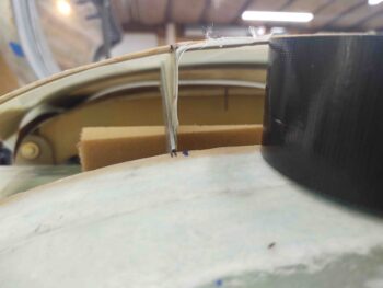
26 October 2020 — Today I dove into testing a myriad of hinge configurations, placements, spacings, etc. for well over an hour before finally getting to the task of cutting out the aft nose/avionics cover hinge mounting brackets out of 1/4″ thick Birch plywood (same as the firewall). Which also took well over an hour cutting and dialing in the bracket fit and hinge geometry.
These brackets are a bit tricky because they have an “ogee” type curve from front to back, but also a side-to-side angle on top to match the curve of the upper inside nose.
Thankfully I had the foresight to test out the fit of the hinges with the NG30 cover before I did the final mount of these hinge brackets.
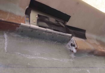
I had them placed where they are below at the outset, but then moved them a good 1.5″ inboard on each side. However, the right hand hinge (left in pic) would have been slamming into the cable bundle that will run along the upper right side of the NG30 cover, the visible bracket being part of the bundle [seriously, a ton of the wires in that cable bundle will be what is currently in that rats nest on the nose floor]. I then had to move the hinges back outboard to my original targeted spot to provide the required clearance. I think it will also make it easier to get the NG30 cover in and out when required, which won’t be often (hopefully!).
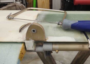
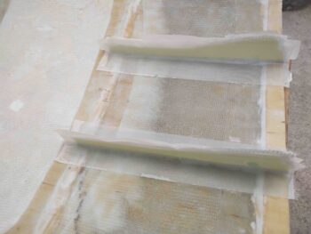
I then set each hinge bracket with 5 min glue with the hinge actually installed on the bracket. I taped a speed square to the canard to help ensure I kept each hinge and bracket vertical, or at least acceptably close.
I then glassed each side of each hinge bracket with 3 plies of BID. If you look closely, you can see multiple hinge pin holes that I drilled as I was dialing in the hinge geometry. I simply filled all but the correct hole in with flox just prior to laying up the glass.
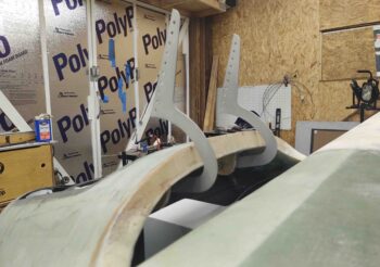
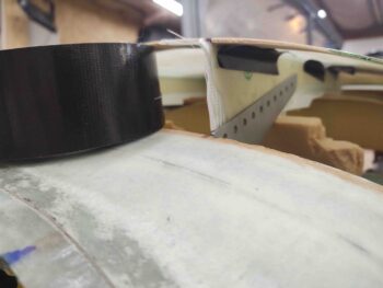
Here’s another shot of the aft nose/avionics cover hinge brackets from the aft side, just over the canard.
And a final side shot of the hinge brackets.

•••
26 October 2020 — I started out today by trimming the aft nose/avionics cover hinge brackets that I installed and glassed last night.
I noted that the hinge configuration worked best with both of them each mounted on the right side. It allows the left hinge to open up more fully, closer in line with the right hinge. And it allows the right hinge to better clear the electrical wire bundle traversing along the upper right side of the NG30 cover.
I ensured the hinges would fit and function with the NG30 cover in place. I’m thinking that’s the first time I’ve installed the NG30 cover since the top of the nose was completed and also with the canard in place.
I was remiss in not accounting for how much G10/phenolic I had on hand, so I just ordered a big piece last night to make the hinge brackets for the cover. The hinges needed to be worked first before most everything else since the swing and settling-in of the aft cover into place will dictate the configuration of most of the other securing points.
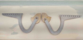
Here you can see the aft nose/avionics cover hinges saluting.
I’m pretty much done with the nose-side aft nose cover hinge brackets, except for trimming them down in size a bit now that I know I don’t need to move the hinge pivot holes.
The hinges aren’t perfectly aligned since the priority was maximized clearance with the canard on the outer edge of the hinge curve, and the top corner of the nose (cross “bridge” piece forward of canard) for the sharp corner of the hinge. There was very little wiggle room before the hinge was either scraping on the canard LE or else unable to travel forward due to snagging on the corner of the nose cross piece. Since the nose isn’t perfect in curvature, and definitely doesn’t have a uniformly curved underside, combined with my forcing an equidistant measurement from centerline, they are off from each other in max opening height and overall elevation… but I don’t see why they won’t still work as designed and I’m very pleased with how they’ve turned out so far.
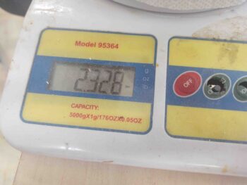
I then got busy trimming down the remaining excess weight on the aft nose/avionics cover.
Not bad… it started at a hair under 4.1 lbs when I pulled it off the nose, and now it’s around 2.3 lbs: a 44% reduction in weight.
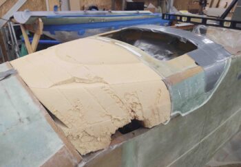
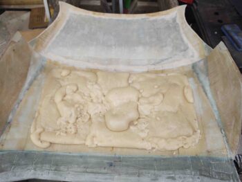
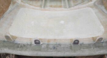
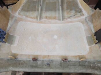
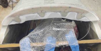
My last task for the evening was to fill the aft depression on the underside of the aft nose/avionics cover with pour foam. Surprisingly, it took me 3 whole sessions to get this area filled. I’ll trim and sand down the foam and prep it for the 1 ply of BID I plan on laying up over the areas that I essentially strip mined for weight reduction.
•••
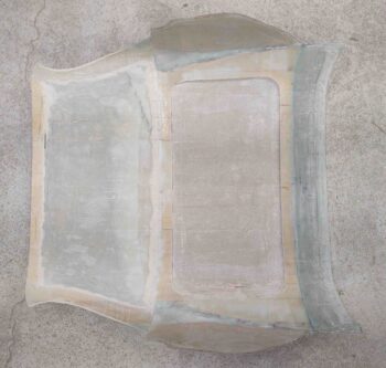
28 October 2020 — Today I sanded the pour foam on the aft nose/avionics cover down (for about 45 minutes) so that it was level with the surrounding surface on the interior side of the cover. I then vacuumed it, and cleaned off the bare glass spots for receiving glass.
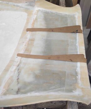
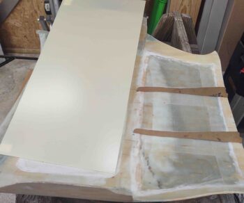
I then made a large paper template to then cut a single ply of BID to cover from the wood lip just aft of the big pour foam area (left in pic) all the way to the front edge (right in pic). I micro’d the foam and also around the edges of the forward bare glass area where it is bordered by wood (and some glass).
I laid up the 1 ply of BID and then peel plied most of the edges… and 2x 3″ strips in the forward bare glass area where the hinge brackets will be mounted.
Yep, this “simple” 1-ply layup took about 3 hours!
•••
29 October 2020 — I started off today by pulling the peel ply and cleaning up the layup on the aft nose/avionics cover.
I then spent a couple of hours dialing in the hinge attach tabs for the aft nose/avionics cover. I had planned on cutting and glassing these in tonight, but by the time I got done with all the nitnoy measuring, aligning, spacing, designing, etc. it was just too late.
Here’s the G10 plate that these brackets will be cut out of:
•••
30 October 2020 — Today I spent a bit of time transferring my cardboard templates for the aft nose/avionics cover hinge tabs onto the 1/16″ thick G10 plate, and then cutting them out on the bandsaw.
After a number of test fits and adjustments, I glassed the hinge tabs to the underside of the aft nose/avionics cover with 2-plies of BID on the inboard edge of the tabs. I then set the cover in place and aligned the outboard edges of the hinge tabs with the hinges to ensure everything was peachy-keen.
After doing an assessment on my CAMLOC situ for the aft nose/avionics cover, I then laid up 2 plies of BID on outboard side of the hinge tabs.
I peel plied those as well and left them to cure overnight.
•••
31 October 2020 — I started out this morning compiling a much needed and much overdue order for Aircraft Spruce, including a few more SkyBolt (CAMLOC) receptacles for securing the aft nose/avionics cover.
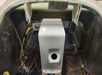
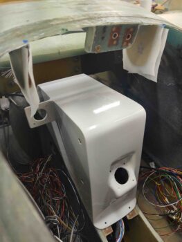
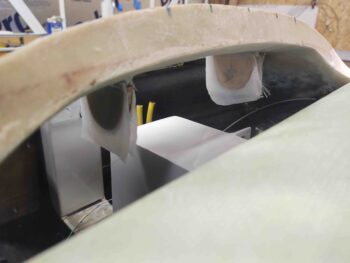
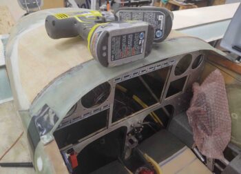
I then dialed in the hinge configuration and got those suckers mounted. Here we have the aft nose/avionics cover in its MG-inspired open position.
Another shot of the aft nose/avionics cover in the open position.
And one last shot . . .
•••
1 November 2020 — I’ll start with a reminder that there will be 4 CAMLOCs across the top of the instrument panel that will lock into 4 tabs to secure the aft nose/avioncis cover into place. I had originally planned on simply floxing the SkyBolt threaded inserts into the tabs, but upon closer inspection I realized they have grooves commingled in the threads where the posts of the 1/4-turn studs lock into. Clearly I don’t want these full of flox.
I checked to see if I had a 1/2-20 tap on hand, which I did, so I tested out tapping a hole in some 1/4″ thick phenolic I had on hand. It held perfectly.
But phenolic is a bit heavy, even though these tabs aren’t that big. I had planned on using the very dense H250 foam, so out of curiosity I drilled and tapped it 1/2-20 as well. To my surprise it held the threads cut into it and securely held the threaded SkyBolt/CAMLOC insert.
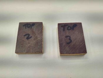
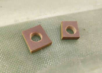
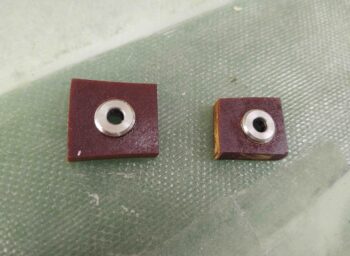
I decided to make the center 2 panel CAMLOC tabs out of phenolic, and the outer tabs out of the lighter H250.
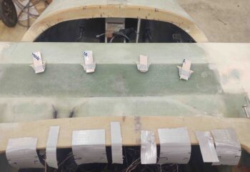
Here are the 2 phenolic center tabs. I forgot to grab a pic of the 2 outer H250 foam tabs.
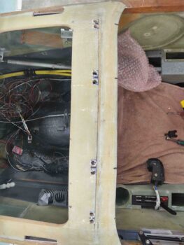
I then finalized the location of the tab through-holes on the top of the aft nose frame, just forward and bordering the original panel bulkhead. I then marked the holes for cutting.

I drilled a 3/8″ hole into each of end of the marked tab through-holes.
And then finished cutting out the CAMLOC tab holes with the Fein saw. I then taped the holes up with duct tape in prep of 5-minute gluing the tabs to the aft nose/avionics cover.
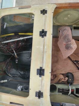
A little bit later, after I 5 minute glued the panel CAMLOC tabs to the underside of the aft nose/avioncis cover, I glassed the forward side of each tab with 2 plies of UNI. I then peel plied the layups.
After the panel CAMLOC tabs’ glass cured a bit on the aft nose/avionics cover, I then remounted the cover back on its hinges and weighted/taped it down. I want the tabs to cure inside the through-holes to ensure they are in the correct position.
I was going to glass the other (aft) side of the tabs tonight, but considering what a pain they’re being with aligning in the through-holes, I want a full cure on them before I glass the opposite side.
The layup schedule BTW is 2 plies of UNI each side of the tabs. Once cured, then I’ll drill a hole and tap 1/2-20 before installing the threaded SkyBolt/CAMLOC insert. Once the insert is in place I’ll glass each side of each tab with a final 1 ply BID that will overlap onto the threaded insert, both front and back.
•••
2 November 2020 — I started out today pulling the peel ply and cleaning up the layups on the forward side of the aft nose/avionics cover thru-panel CAMLOC tabs. I then laid up 2 plies of UNI on the aft side of the tabs overlapping about an inch onto the underside of the cover. I peel plied it and left it to cure for a couple of hours (before mounting it back in place on the nose, to ensure the tabs cured in the correct position). Sorry, no pic of this.
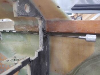
After an hour or so assessing my interlocking hinge securing points for the aft nose/ avionics cover –located on each longeron just forward of the paneI– I then got busy making up some steel 1/4-20 threaded hardpoints to secure the interlocking hinges’ pin knob, which will be on the face of the panel in each upper corner.
When I want to open the aft nose/avionics cover, part of the process will be to unthread these knobs, about the size of dimmer switch knob, and slide the pins out of the interlocking hinge pins along the longeron. Another securing point/release for the aft nose/avionics cover. To remount the cover I’ll simply reverse the process: insert the interlocking hinge pins and thread the knob in the secure/closed position.
I was leaning towards using a 10-32 nutplate or RivNut to thread the knob into, but after assessing the hinge pin diameter I needed a bigger threaded screw-post that will both secure the hinge pin in place and the attach to the knob (used to insert/remove the hinge pin). It will become more clear over the next day or so… and as I said on the nose hatch video: I plan on making another one for the aft nose/avionics cover.
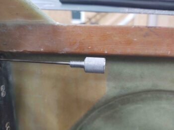
Here are the 2 steel 1/4-20 threaded panel inserts. I lathed 3 flox grooves around the outer surface for better gripping in the 3/8″ holes I drilled into the panel. I then floxed these guys into place…
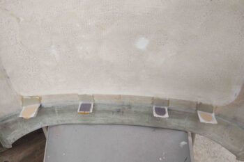
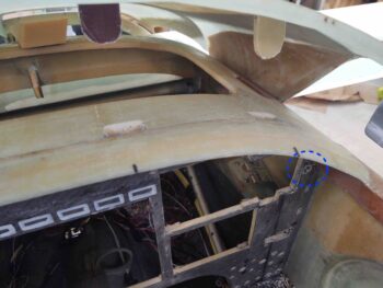
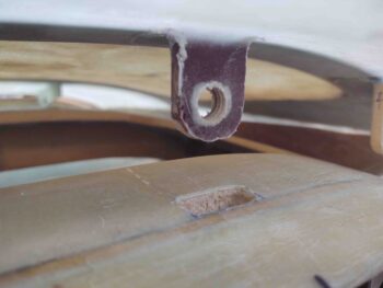
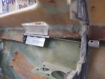
Back to the aft nose cover thru-panel CAMLOC tabs… here they are all glassed up with a quick trim.
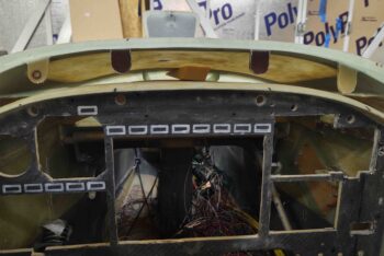
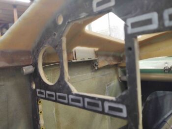
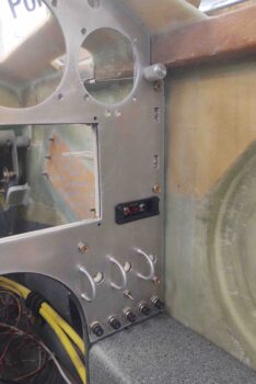
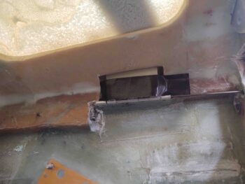
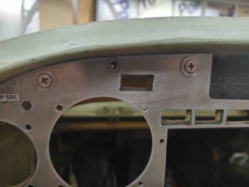
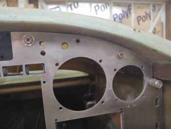
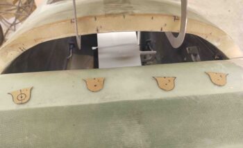
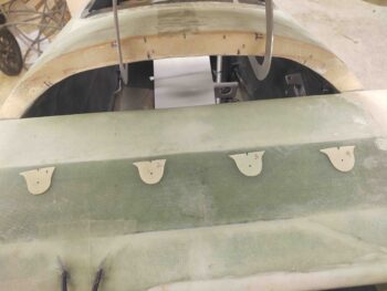
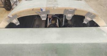
And here’s a shot of them with the slots on the top surface of the aft nose sub-structure that allows the tabs to fall right into place behind the panel [the right pic also has a shot of the right side steel threaded panel insert floxed into place (blue dashed circle)]
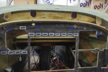
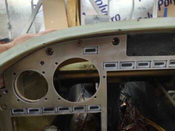
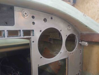
I took this shot of the panel to show the 4 associated CAMLOC thru-holes on the panel for each tab (blue arrows).
Another shot of the tabs with the cover open, for a bit of overall size perspective.
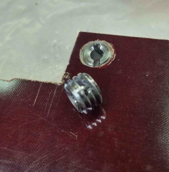
Here we have tab #3 after I drilled it out and tapped it with 1/2-13 threads… the threads are actually visible in this pic.
I then threaded a SkyBolt (CAMLOC) receptacle into each tab. After some thought yesterday I decided to also flox these in place as well… so each receptacle was slathered in flox before threaded into place. I then spent a few minutes on each one to ensure no flox was where it shouldn’t be.
After the tabs were all cleaned up, about a half hour later, I closed the lid and grabbed a shot of the threaded SkyBolt/CAMLOC receptacles peeking though their respective holes in the panel.
With that, I left the floxed homemade threaded inserts and the threaded/floxed SkyBolt receptacles to all cure overnight.
•••
3 November 2020 — I started off in the shop today glassing the aft side of each aft nose/avionics cover tab with 1 ply of BID. I then peel plied the layups.
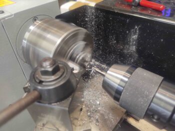
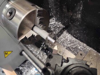
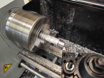
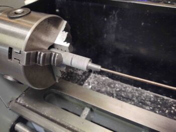
I then got busy on the lathe machining the knobs that secure the wire pins for each interlocking hinge assembly which is another added securing point for the nose cover.
I made up the first knob to ensure it would work, and as you can see here it does. The wire pin does have to contort just a bit, but not bad enough to stop this from working (as I can tell so far).
When the hinge pin is out to raise the aft nose/avionics cover, it will have a hard stop (which I plan to work on tomorrow) that keeps the pin in the last segment of the nose (longeron) side of the hinge.
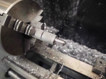
Here’s a clear picture of the knob that attaches to the hinge pin via a set screw.
I then tried the same initial knob/pin assembly on the left side, which worked out just as well.
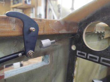
I then tested it with the forward CL-2 canopy latch hook to ensure there was clearance when the hinge pin was all the way out (aft), and as you can see there is.
With the first hinge pin knob looking good, I started in on knob #2.
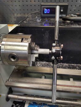
This is the first time I’ve knurled something, and since I tried to do it for both knobs altogether, it flexed the aluminum rod a bit and didn’t quite get the bite I was hoping for. But it still turned out acceptable, so I pressed on.
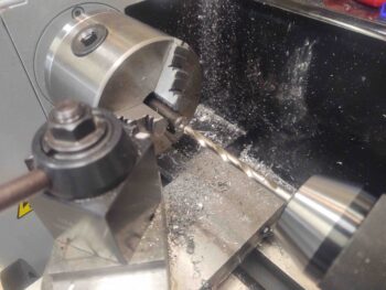
Here I’ve added some pics showing how I used a die to cut the 1/4-20 threads.
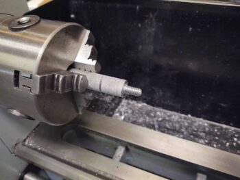
I then tested the drilled center hole to see how the wire pin fit… nice and snug.
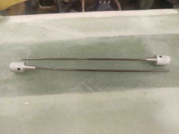
Here are the left and right knob/hinge pin assemblies for the aft nose/avionics cover.
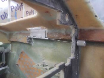
Here is the right knob/pin assembly installed.
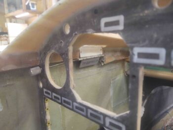
And the left.
By this point in the evening, the BID on the aft faces of the CAMLOC hinge tabs was cured, so I trimmed and cleaned them up before glassing the forward tab faces with 1 ply of BID.
Here’s a final shot with right knob/hinge pin assembly in place as well as the lower right panel.
•••
4 November 2020 — I started out the day once again pulling peel ply and cleaning up the layups on the aft nose/avionics cover thru-panel CAMLOC hinge tabs, only this time on the forward (nose) side of each tab.
I then configured and designed the G10 tabs for the aft nose/avionics cover interlocking hinge latches. I was in a rush since my friend needed someone to watch her daughter for most of the day as she went to an appointment: The result was round 1 of the hinge tabs —when I assessed them later– once in position at my desired mounting point on the inside surface of the aft nose/avionics cover, turned out to be too short to comfortably fit the 2 rows of rivets I planned on using to secure the G10 pieces to the aluminum hinge sections.
Of course I discovered all this much later in the evening, at which point I got busy redesigning the next version of the G10 tabs for the aft nose/avionics cover interlocking hinge latches. On these new versions I really only added about a 1/4″ along the bottom edge next to the actual hinge tabs to –again– ensure enough area to have 2 row of rivets.
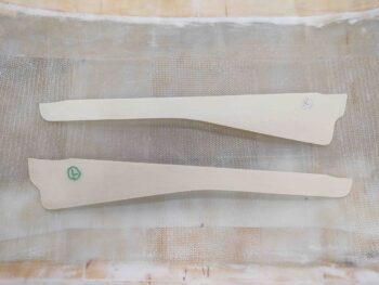
So here we have the final versions of the interlocking hinge tabs that will be installed.
The install process will be to 5-min glue these to the underside of the aft nose/avionics cover when it is in the down position, with the hinge pins installed. One reason I needed taller G10 tab sections is that I wanted to push the attach points to the inboard on the aft nose/avionics cover. This will align these tabs more center in the thru-holes in the aft nose substructure, and also provide more clearance with the protruding rivets since I wanted to mount them head side on the G10 for a more secure grip.
•••
5 November 2020 — I started off today installing the aft nose/avionics cover interlocking hinge tabs with the pin installed, and then 5 minute glued each one to the underside of the aft nose/avionics cover.
I let it cure for quite a while before pulling off the aft nose/avionics cover and then glassing each interlocking hinge tab with 2 plies of UNI and a ply of BID.
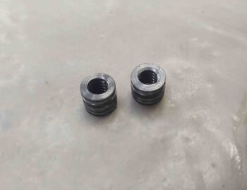
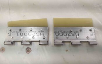
I then drilled and tapped two 1/4″ phenolic pieces for 1/2-20 thread. I then cut the pieces out on the band saw.
These will be inserted into notches on the internal nose sidewalls to accept the same SkyBolt/CAMLOC threaded receptacles as I used on the thru-panel CAMLOC tabs. I assessed that at high speeds these thin side “flaps” may do exactly that: flap. So I decided to nail them down at the corner with a CAMLOC stud.
Visually this CAMLOC will reside at the tail end of the elevator fairing.
My last task for the evening was to glass the outboard layups for the aft nose/avionics cover interlocking hinge tabs.
•••
6 November 2020 — This morning I pulled the pins and popped open the aft nose/avionics cover with the cured interlocking hinge tabs working as designed.
•••
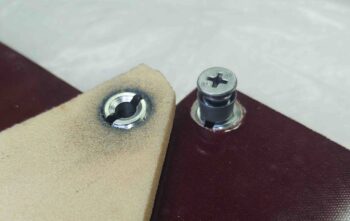
9 November 2020 — I returned home today to find a delivered FedEx box from SkyBolt with my “CAMLOC” studs for the thru-panel tabs to secure the aft nose/avionics cover.
I took the SkyBolt studs out to the shop and tried them out. These are the shortest of the ones I ordered (-10) and as you can see, on the right side I probably need to drop down a size. (Later I ordered some -9s and -8s).
Still, I’m happy with how they look, fit and function… and could certainly use all of these in the interim while waiting to replace the slightly-long stud on the right side.
•••
10 November 2020 — I gathered up my phenolic plates with 1/2-20 tapped holes in them, along with the SkyBolt threaded ‘CAMLOC’ receptacles to assemble. I was going to flox the receptacles in tonight, but I wanted to wait until I had other glassing to do since I always make up too much epoxy, even with just a gram or two, than I need when doing such a small flox job.
I understand that these phenolic pieces look a bit wonky and not symmetrical. Part of my issue is these are 1/4″ thick, and my band saw is a small cheap one that wonders on any thick piece. The size difference is due to the right one originally being just a test piece, but then I don’t like wasting expensive material, so I used it for this. Once embedded into the nose sidewall, these will never see the light of day and their hideous disfigurements hidden except for the couple of pics of them in this blog.
•••
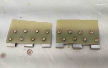
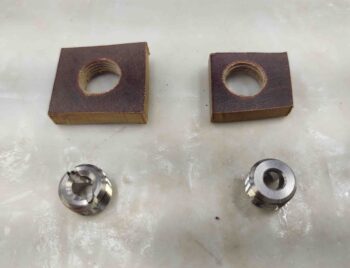
11 November 2020 — Today I floxed in the 2 SkyBolt threaded receptacles into their respective phenolic blocks. Here’s the front (outboard) sides.
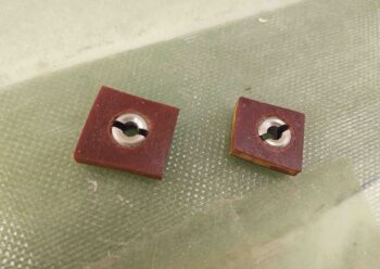
And here’s the back (inboard) sides.
•••
20 November 2020 — I tried out my new shorter SkyBolt/CAMLOC studs on the right side of the panel. The far right stud is a -8, while the one towards the center is a -9. Clearly these fit much better than the -10s I had before.
•••
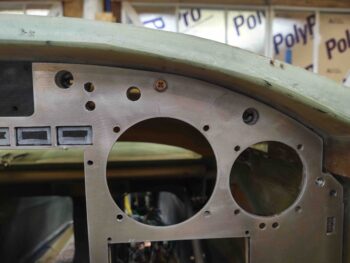
25 November 2020 — Today was all about the 4 CAMLOC hardpoint tabs along the front edge of the aft nose cover, only focusing on the nose bridge tabs first. These tabs will simply have holes in them where the CAMLOC/SkyBolt stud will fit through and lock into the CAMLOC/SkyBolt receptacle attached to a front interior lip (which at this point does not exist) of the aft nose/avionics cover.
My first decision point was that there would in fact be 4 CAMLOC attach points, positioned in spots where the mating points on the cover could swing down and clear the canard (for the outboard points) and that I could access them easily enough over the top of the NG30 (for the inboard points… note NG30 set back in place to check clearances). I’ll point out that these hard points are NOT symmetrical about the nose centerline since the cover’s hinges both attach on the right side of the hinge mounting tabs.
I then designed the CAMLOC hardpoint tabs with enough clearance around the stud hole to be strong enough to secure the front edge of the aft nose/avionics cover (above). I then cut each tab out of 1/16″ thick G10 and sanded down each side for texture to get good bonding for glass. I also pre-drilled a small starter/alignment hole at the hole center of each tab.
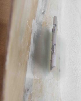
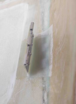
To ensure the tabs were an straight-line extension of the aft edge of the nose bridge, I taped a short length of a big popsicle stick to each tab.
I then 5-minute glued just the top edge of each tab to the underside edge of the nose bridge.
I let the 5-minute glue cure for about a half hour while I made a template and then subsequently cut out a ply of BID for the entire nose bridge aft face, including the newly mounted CAMLOC tabs.
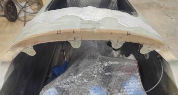
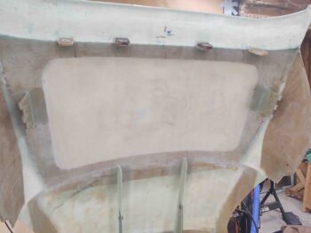
After cleaning off the scant bit of excess 5-minute glue on each tab/nose junction, and also creating flox corner edges in the exposed foam on each side, I then laid up the ply of BID. I then peel plied the layup.
A few hours later I pulled the peel ply on the aft nose/avionics cover front nose side CAMLOC tabs. I then did a quick razor trim on the edges. I’m really happy that the tabs are installed and aligned with the nose bridge cross face, and also that I no longer have any exposed bare foam in the upper nose area around the canard.
•••
15 December 2020 — I started off tonight with some layups to get something curing right off the bat. I cut and pre-pregged 4 sets of 2-ply BID for the front side of the 4 CAMLOC tabs that will secure the front side of the aft nose/avionics cover.
After I laid up the BID I peel plied it.
Here’s a couple shots looking aft at the right side and left side pairs of CAMLOC tabs.
A number of hours later the layups on the nose CAMLOC tabs had cured, so I pulled the peel ply and did a quick knife trim on the layups.
•••