
Chapter 19 – Ailerons
6 June 2013 — Today I started off by Alodining 2 each aileron torque tubes.
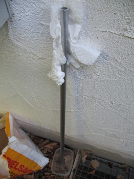
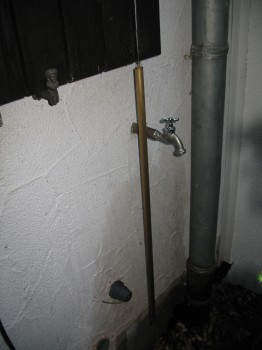
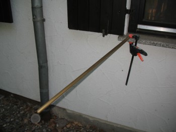
For the aileron torque tubes I used 1 meter long PVC pipes capped on one end to Alodine the tubes, and then I simply hung one up to dry and clamped a dowel to the window ledge with the torque tube slid over it for the other one to dry.
•••
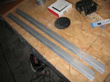
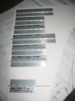
15 June 2013 — I started by marking up a P6 hinge and cut 2 each 8″ lengths & 4 each 6″ lengths out for the ailerons (enough for both wings). The aileron hinges look offset in the pic below because they are: one side must be reversed because this is how the hinges are mounted to the ailerons & wings.
I also cut out a 4″ length for the rudder (which typically takes the smaller P5 size, so I’ll just trim it down to size). For now I’ll wait on cutting the rest of the rudder hinges since I don’t have any P5 size hinges on hand, however, since I do have another P6 hinge set on hand I will probably rip it to width, and then cut the lengths out later on.
•••
16 June 2013 — I finished up the evening by taking the long aluminum “board” with sandpaper on the edge & giving the Left wing TE and a good sanding. I also re-checked the measurements & shape of the TE.
I then measured, marked & drew out the aileron outline for planning.
•••
20 June 2013 — I started today by pulling the peel ply from the Right wing root LWA7 layup & the aileron control tube channel.
I then razor trimmed the LWA7 BID layup.
I drilled a 1-1/8″ hole to expose the aileron control tube channel in the Left & Right wing roots. I then used a 1″ sanding drum on a drill & a mini-drum on the Dremel tool to widen the hole diameter to around 1-3/8 inches. . . enough to slide in the aileron control bearings that I picked up from JD Newman at Infinity Aerospace (the same place I got the fighter style stick grips).
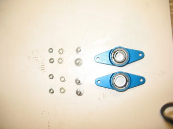
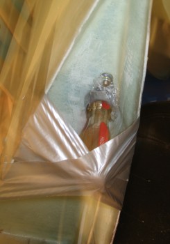
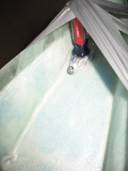
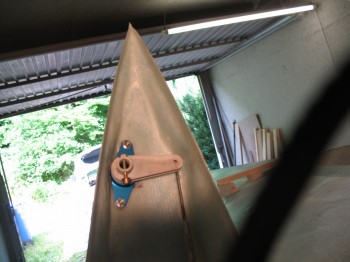
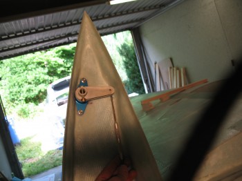
I followed the directions JD sent. First, I covered the main bearing assembly with cling wrap, then cleaned off the Clickbonds with Acetone, and finally roughed up the bottom attach surfaces of the Clickbonds with sandpaper in prep for floxing them on.
I then mixed a whole wopping 6 g’s total of wet flox slurry & mounted the Clickbond/ Bearing assemblies to Left & Right wing roots. As you can see below I used a large screwdriver through the center hole on each assembly–duct taped in place to each wing–to keep pressure on the aileron bearing assembly, and thus the Clickbonds getting floxed onto the wing root surface. I then let the flox cure.
•••
21 June 2013 — Today I started by finishing up the installations of the Aileron control system bearing that is mounted at the end of the aileron control tube channel that begins (or ends, depending on which way you look at it) in the wing root area. The original plans calls for simply glassing in a phenolic plate with a hole drilled into it to be used as the aileron control system bearing. This is also what is called out in the plans on the fore & aft ends of the Chapter 16 control system tube that I mounted the brackets for inside the fuselage a week or so back. Most newer EZ’s that I’ve researched have upgraded to the type of bearings that I’m using here, sold by JD at Infinity Aerospace. The problem with phenolic is that it eventually wears out a little bit, widening the hole and thus allowing just a bit of slop in the control system. Of course this slop, even a little bit, isn’t good but can be prevented by installing actual metal control system bearings.
•••
22 June 2013 — I started today by testing the clearance inside my Right wing root for the Aileron Tube Bellcrank (CS-132) that I purchased from the Cozy Girrrls. There is a possible clearance issue if not enough foam is removed from the bottom edge of the wing root. I mounted the the CS-132 to the aileron bellcrank bearing tube (CS-152) and then slid that into the aileron tube bearing assembly that I had just mounted to the wing root via Clickbonds (click here for info from the Cozy Girrrls on Clickbonds).
Fortunately for me I had measured correctly so I had no clearance issues with my Aileron Tube Bellcrank, and it rotated freely in both directions.
•••
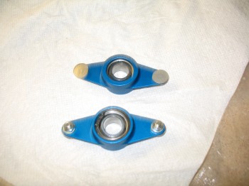
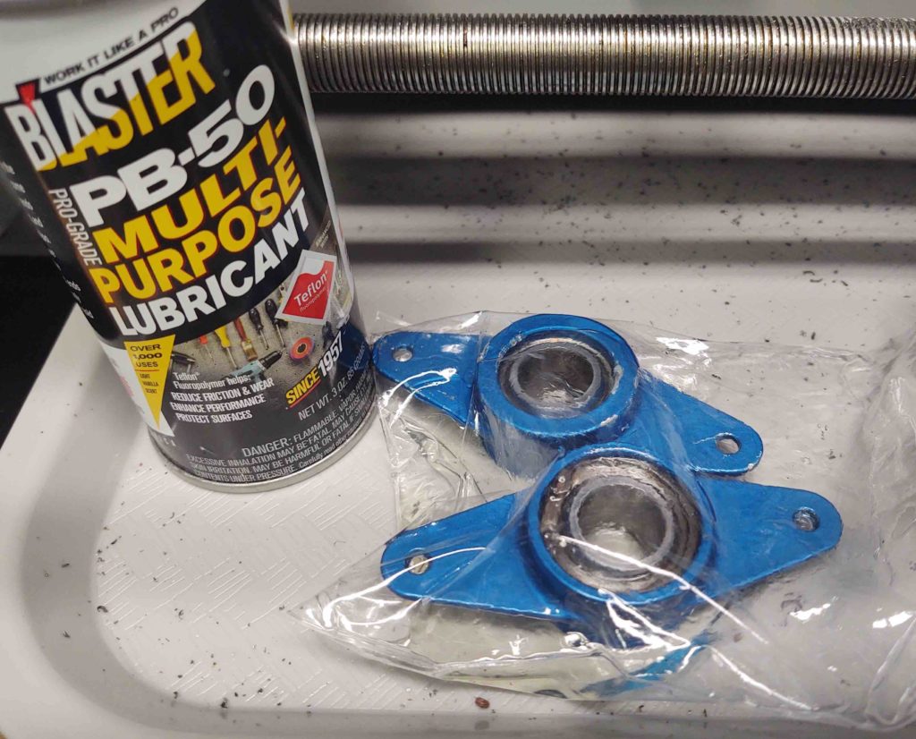
26 August 2020 — An item on my list was to remove the aileron bearing assemblies from the wing roots and soak them in PB Blaster for a few days.
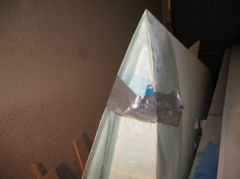
They suffered from a bit of corrosion while in storage. You can see some rust in the pic below.
Here they are getting a bath in PB Blaster for a few days. I’ll clean up and assess after that.
•••
27 August 2020 — Today I went ahead and knocked out re-floxing the right wing aileron bearing aft (upper in pic) clickbond. The glass around it didn’t look so great when I pried off the bearing assembly, thus I had planned on remounting the clickbond anyway. Not wanting to waste any expensive MGS epoxy, I put it to good use here.
•••
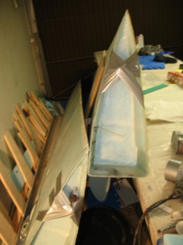
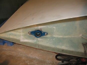
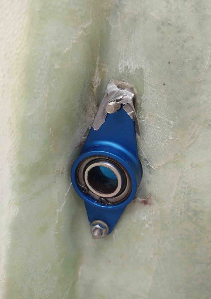
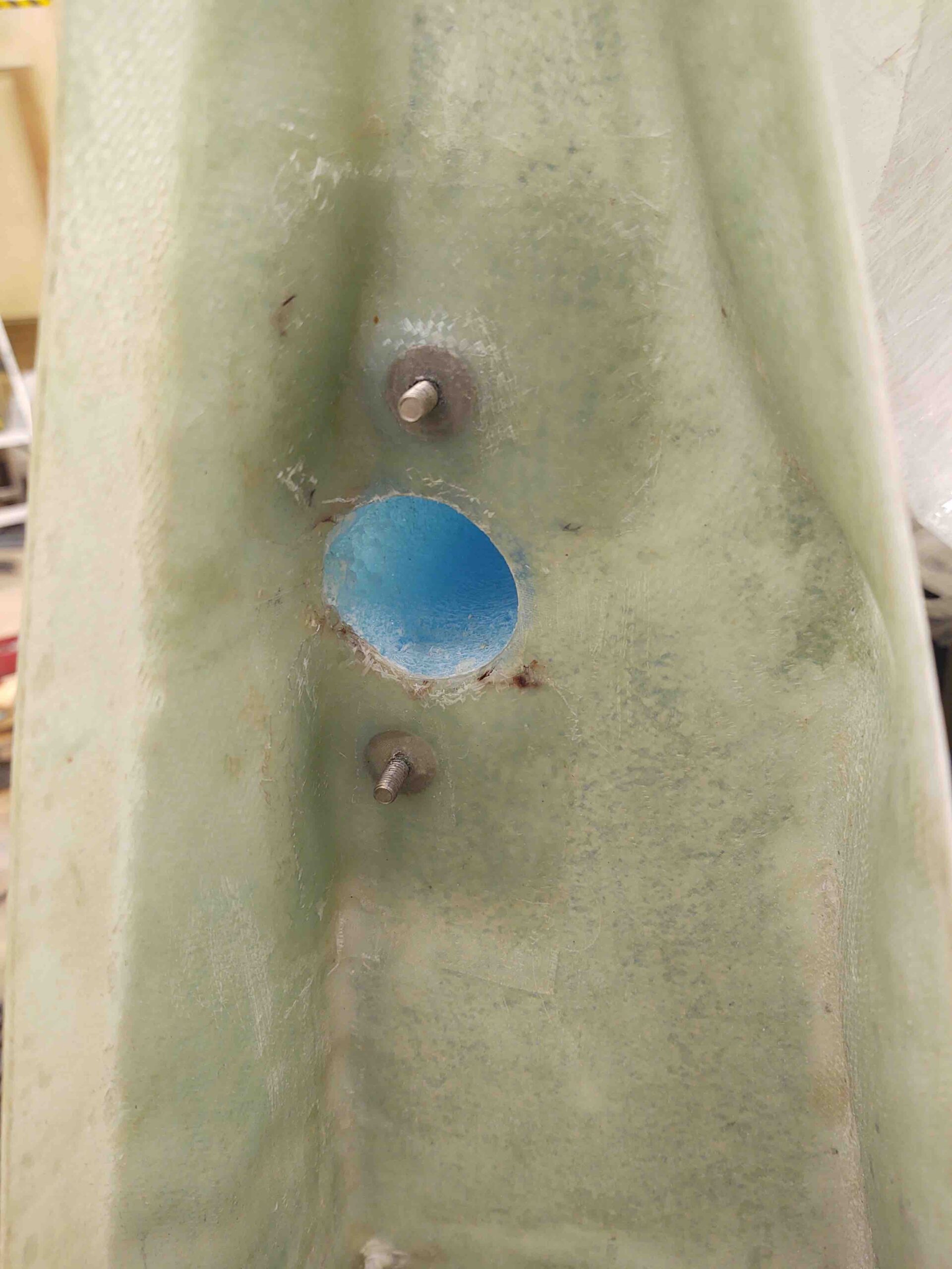
31 August 2020 — Today I (re)glassed the right wing’s aileron bearing assembly’s aft retaining click bond (top below) with 3 plies of BID [since I just remounted the click bond] and 2 plies of BID over the forward click bond (bottom below) just for good measure.
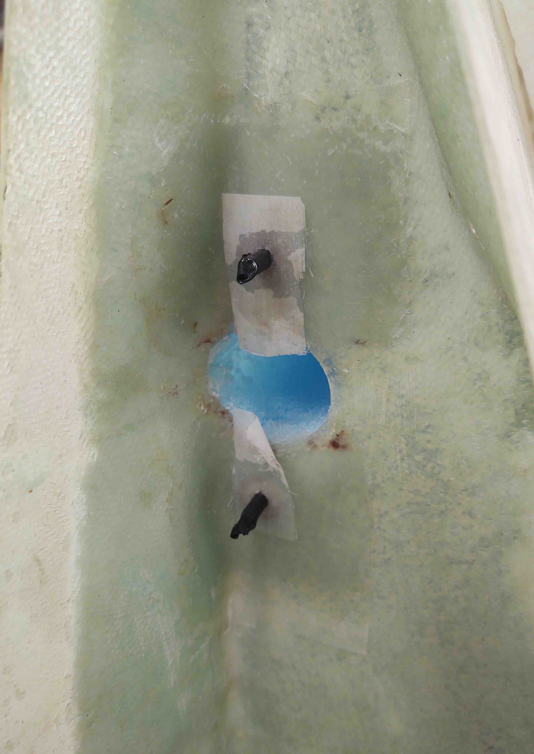
I’ll jump ahead here and show you the finished product a few hours later after I pulled the peel ply and trimmed up the glass overhanging the hole.
•••