
Chapter 23 – Engine Pickling
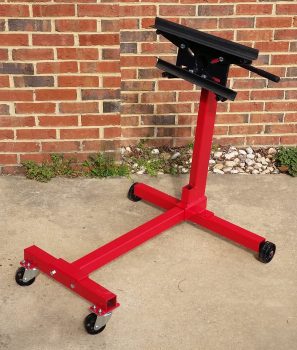
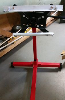
18 March 2018 — I had 2 major issues regarding engine preservation that until this afternoon were unresolvable: 1) I needed to be able to cycle through each cylinder to TDC and BDC for spraying preservation oil into the cylinders. Clearly I couldn’t do this with the engine dangling by a chain on a hoist. 2) I needed to be able to rotate the entire engine upside down to bath the cam in oil/preservation juice. To solve both these issues –and be able to have the engine on-hand but stored in a smaller form factor– I bought an engine stand from Harbor Freight that allowed me to mount the engine to the stand so that I can handle the 2 issues that I mention above.

•••
22 April 2018 — I started out today with kind of a fun little project: assembling the engine stand that I picked up at Harbor Freight with a 20% off coupon. As I was assembling it, a note in the instructions caught my eye: “Not for use with Aircraft”… hmmmm?
I also set the lengths of angled steel on the top and bottom mounts to provide an idea of how those will mount to both the engine stand and the engine mount (this angled steel was one of the pieces that Marco cut for me on his ginormous metal band cutting saw… which cut through this stuff like butter!).
•••
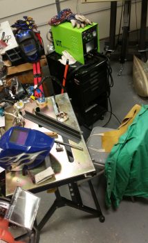
23 April 2018 — After the prop and fuselage pics were all taken, I then spent a good bit of time setting up my TIG welding kit for a good bit of welding that I need to do. It’s been so long since I’ve welded with this box that at first I thought it was in-op. Since this welder does stick welding as well, the ground connection on the front of the box is for stick welding, and the ground lead for TIG is actually labeled with a “+” sign…. which I finally figured out after spending a good amount of time tearing it apart and going through all the troubleshooting guides.
•••
24 April 2018 — I started off today prepping some of the metal that I’ll use in constructing the mounting brackets that I’ll mount the engine & engine mount to on the engine stand (say that 3 times fast).
From there I headed to my local Village hardware store for some 1/2″ nuts & bolts for the engine mount stand brackets.
•••
25 April 2018 — Today I started with a 1″ x 1″ angled steel bar that I had on hand. It had some surface rust but I was able to remove the majority of it. I then marked 4 x 1.5″ tabs on one end, drilled holes that would allow for a welded “hardpoint” between the flat intersecting pieces of metal being welded together, and cut the 4 x 1.5″ mounting tabs from the angled steel extrusion.
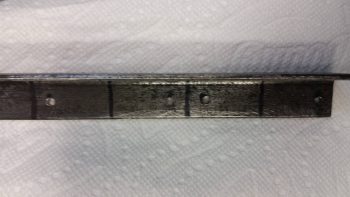
I then set the mounting tabs on the associated 1.5″ x 1.5″ angled steel main engine stand bracket cross pieces –top & bottom– to ensure I had them set in the right places.
Now, as I mentioned during my TIG welding setup it’s been a couple of years since I’ve welded, but with both the high expense of Argon gas and my limited time I jumped right in. I knew there was Argon in the bottle, but it was low enough it wasn’t really registering well. In addition, the nifty little cheat sheet weld chart that Lincoln gives out during the EAA Tig Welding Workshop called for a 3/32″ Tungsten electrode for 1/8″ steel. I only had 1/16″ on hand.
Nonetheless, I trudged forward and laid down some appropriately crappy welds my first go at it. Towards the end of it I could tell I was definitely out of Argon gas, so with about 45 min left before the Gas shop closed I threw my empty tank in the truck and went on my quest to collect a fresh UBER EXPENSIVE ($90!!!) tank of Argon. [As a point of note, I ground and re-welded any of my initial welds that looked lacking in the strength department… with my limited time available, ugly welds here were acceptable as long as they were strong!]
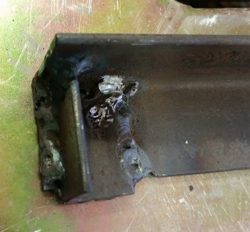
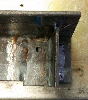
Upon returning back to the shop with a fresh full tank of Argon and some 3/32″ electrodes, this was what the other side welds looked like. Just a tad better I’d say… (yes, still not up to par with the gorgeous TIG welds we see on YouTube, but again, strength was what I was after here, not necessarily beautiful welds!).
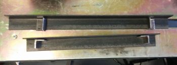
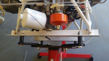
With the lower engine stand mounting bracket complete, I then started on the top bracket. Once I was finished with the top bracket, I spray painted both engine stand mounting brackets with the same fast drying white paint that I used on the engine mount.

When the quick dry paint had cured I then determined the best bolt hole locations for my configuration and drilled out the 1/2″ holes that allowed me to bolt the respective engine stand mounting brackets to the beefy engine mounting arms.
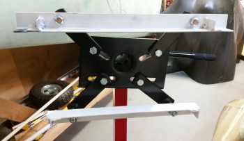
Here’s a closer shot.
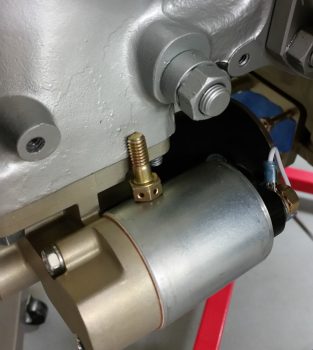
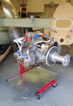
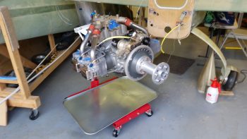
With the engine mount ready to go, I then unmounted the engine from the fuselage. I took this pic because I would often bump the engine and the starter bolt that I had setting in this location would fall off onto the shop floor. However, it stayed right in its spot the whole time I removed the engine from the fuselage, so the operation must have gone fairly smoothly . . . both literally and figuratively.
•••
26 April 2018 — With having removed the engine last night from the fuselage, I then did the limited trial and error dance for getting the bottom engine stand mounting bracket mounted to the engine mount.
However, the top mounting bracket was the big dance, and it took a couple of hours to dial that baby in. The primary issue was that I forgot how the engine mount stubs –and thus the engine mount extrusions– are at a slight angle to follow the fuselage angle (this is denoted in the plans).
After much wailing & gnashing of teeth, a number of expletives and my new boneyard of broken drill bits (I think one side of the mount ended up so hot that it was in an annealed type state… since drilling a hole into it was like going through stainless steel) I finally got it all put together and then the engine mounted to the stand!
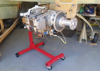
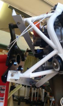
Here’s a better view of the engine mount attached to the engine stand mounting brackets.
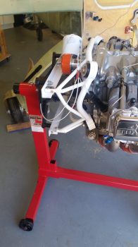
And a couple of views from the top.
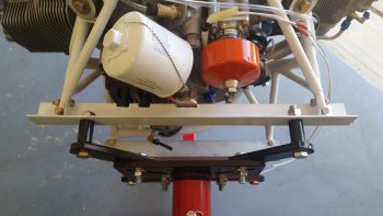
Ah, yes, and of course here we have a view more from the lower side.
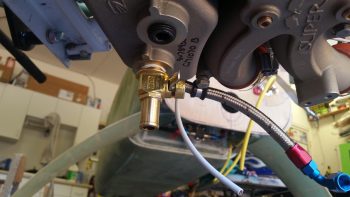
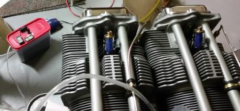
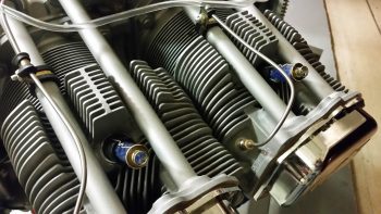
I also drilled a hole through the lip of the oil drain valve to accept a 0.041″ piece of safety wire. I then threaded the oil drain valve in place. Unfortunately I was remiss in remembering that this was a Japanese made oil drain valve, and thus metric, so my 3/4″ wrench was just a hair loose on it. When I really went to snug it up that last little bit I rounded a couple of the wrench flat corners over. I then grabbed a 19mm wrench to finish up the last little bit of snugging it up tight.
I removed the spark plug cylinder dehydrators from the bottom side of each cylinder and replaced them with standard aircraft spark plugs. I then removed the top spark plugs while I squirted preservation oil into each cylinder, and then replaced them with standard aircraft spark plugs as well.
I sprayed approximately 2 oz of PolyFiber Engine Storage Oil (ESO) into each cylinder when its piston was in the down (inboard) position. I will admit that I realized as I was prepping for the pickling of the engine that an optimum solution would have been to have cover plates for both the intake and exhaust manifold ports, but I didn’t have either, and again, since I was in a time crunch I pressed forward and simply placed an oil drip pan underneath the engine for any runoff.
I will say that I shown a pen light into each cylinder with the top plug out, and what I saw on the each cylinder wall gave me a huge sense of relief. I could see the honing of each cylinder wall with bright shiny metal and NO corrosion…. which I’m very thankful for.
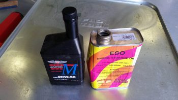
I then poured 3 quarts of Phillips 66 20W-50 oil into the engine, fed in the remainder of the ESO and then poured in an unused quart of Harley-Davidson 20W-50 to top it off.
With my 4+ quarts of oil in the sump, I then flipped the engine upside down and let it sit that way for a good 5+ hours as I loaded up my rented moving trailer. My goal here of course was to bath the top-mounted camshaft in a bunch of oil.
In my haste I failed to cap the oil heat return fitting so it spit out a bit of oil when I flipped the engine upside down. Beyond that little issue the engine stand seemed to work exactly as I thought it would in allowing me to wrench on the engine and also rotate it as if it were on an “engine spit.”
Before I left for NC I turned the engine back right side up and attached the hook of the engine hoist to the top engine lifting tab. I’ll turn the engine back upside down when I return from NC, but since I just welded up the engine stand mounting brackets I didn’t want to test my luck (just in case).
I did leave a bit of a gap between the engine hoist hook and the engine lift tab to allow me to quickly identify if any of the welds on the engine stand mounting brackets gave way while I was gone…. again, just a precaution with an expensive aircraft component.
For the final push on the engine pickling, as I was working on the engine I was also concurrently baking up another batch of pink desiccant. Once it had turned blue and cooled, I then recharged all the cylinder dehydrators and the main engine dehydrator bin. I then removed the top spark plugs and replaced them with the spark plug cylinder dehydrators. Note that now the spark plugs are mounted on the bottom of each cylinder with the spark plug cylinder dehydrators on the top.
•••