
Electrical System Documentation
This page covers electrical schematics, wiring diagrams, miscellaneous electrical system documentation and wire books.
7 May 2014 — I have been working on my Electrical System since September of 2012. More recently, over the last 6 months, I’ve been trying to get it as close to finalized as possible before I head back to the States… and commence to start building in earnest. One goal that I had while being separated from snorting epoxy fumes and getting touchy-feely with itchy fiberglass for the past year of this build was to complete my electrical system wiring book. I want a solid plan to follow once I get to the point of wiring up this bird, and I don’t want to be in a position of trying to design my wiring system as I install it, or worse, take precious time away from actually wiring the plane to research out what I’m supposed to do, or how to do it. Of course, my overall goal is to have a very optimized, efficient and as Bob Nuckolls would put it, “elegant” electrical system (all that equaling ‘safe’ too!).
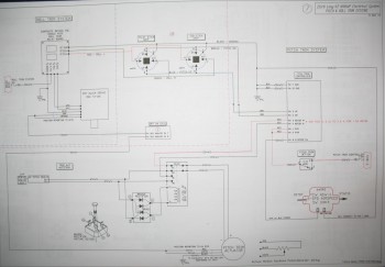
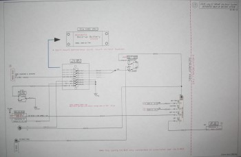
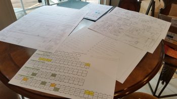
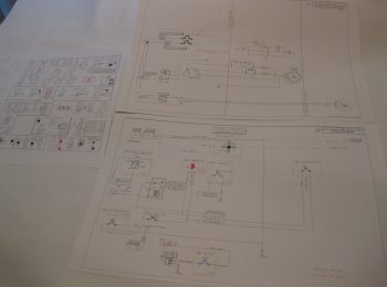
Pic below shows Switch page (L side) and Z13-8 Main Electrical System diagram (Lower L) along with five other electrical subsystem diagrams.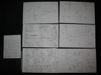
Of course another reason for me to document my electrical system & wiring, and the foundational research that goes into all that, is to have reference documents to go back to in case something just ain’t working right!
So a couple of months ago I felt my electrical system was to the point where I should start diagraming out the electrical subsystems. Thus, over the past couple of months I’ve started in on the individual pages–one for each subsystem–of the Wiring Book. Below is the ever-expanding and ever-morphing list of subsystem diagram pages for the Wiring Book (Green denotes completed or mature, yellow is currently being worked):
Z. Z-13/8 Electrical System
– Switch Configuration
1. Panel Components
2. Radio & audio system
3. Main Bus
4. Batt Bus
5. E-Bus
6. Nose Gear
7. Pitch & Roll Trim Systems
8. Lights: LDG, TAXI, NAV, STROBE
9. Engine Info Management
10. Fuel System
11. Cockpit Lighting
12. Landing Brake
13. Throttle Switches
14. Control Stick Wiring
15. Integrated Back-up Battery System
16. Alarm & Warning Systems
17. Charging & Starting Systems
18. Heater System
19. Electronic Ignition
20. P-Mag Ignition
The wiring pages for the individual busses (#s 3-5) will be created last after all the minutia is flushed out and sorted through for each subsystem. It’s amazing the amount of research, emails, and phone calls, etc. that goes into creating each subsystem diagram. Of course, it’s an understandable dynamic that more companies producing components for homebuilts gear them towards the RV crowd, simply because that’s arguably the most often built experimental in el mundo. Unfortunately, this can create issues for us Canardians as we fervently try to cram RV-oriented electrowhizzies into our prized EZs. Also, it’s simply a matter that a lot of these smaller companies just haven’t got around to engineering a solution between their and other products that can work in our canards.
A good example of this is when I had to contact both TCW and Trio to figure out how to get the Trio A/P AutoTrim function to work with TCW’s SafetyTrim Pitch Trim Controller. Both companies were of course fantastic, but it took a good day and a half to work out and confirm a solution. And that’s for just a few wire connections between two devices. Clearly most of us have a fair number of electrowhizzies in our birds, and luckily most of this stuff is figured out ahead of time . . . but definitely not all the time!
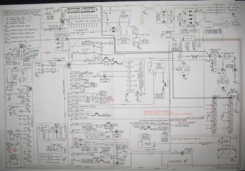
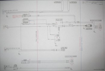
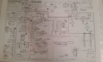
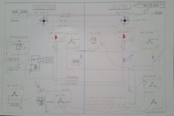
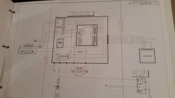
Below is a shot of my main wiring diagram for the Z-13/8 electrical system architecture that was developed by Bob Nuckolls from The AeroElectric Connection fame. I have of course taken the basic diagram and modified it countless times for my purposes. If you are building an airplane and don’t have this book, get it! I seriously don’t know how you could wire an experimental airplane without it.
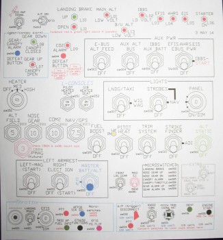
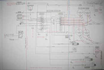
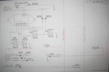
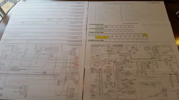
Here below is a shot of my switches, circuit breakers, and LED lights diagram. Notice that each device is numbered with a specific code. These codes are depicted wherever the device shows up on any given wiring diagram. They’re also annotated on a spreadsheet that I keep all these device codes in, and will be incorporated into a wiring identification schema which will be labeled on each wire. Once the labels are on the wires, I’ll be able to look at any wire and its associated 12-digit code, tell exactly what device the wire is coming from and from what area (nose, engine compartment, etc) of the aircraft, what device and area it’s going to, and its function.
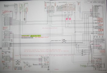
Below is a working copy of my panel wiring diagram. I spent nearly a week working off & on to upgrade the diagram so it depicted the Garmin GTN650 pinouts vs the Garmin GNS430W.
And finally, here’s a shot of the Pitch & Roll Trim Systems wiring diagram:
•••
17 May 2014 — In the past week I’ve completed a few more wiring diagram pages for my wiring book: the Electroair electronic ignition, the P-MAG ignition and the Engine Info System (GRT EIS4000).
Here is a shot of my Engine Info Management wiring diagram page:
Along with knocking out some wiring diagrams, I also added a couple more diagrams to the list of subsystem diagram pages for the Wiring Book. I broke out the Starting system to its own page, and to keep track of all the wiring and to have a holistic, systemic, wire-focused (vs component-focused) view of my system, I added a Components Interconnect page. Below is the updated list that I shared last week (again, green denotes completed or mature, yellow is currently being worked):
Z. Z-13/8 Electrical System
– Switch Configuration
1. Panel Components
2. Radio & audio system
3. Main Bus
4. Batt Bus
5. E-Bus
6. Nose Gear
7. Pitch & Roll Trim Systems
8. Lights: LDG, TAXI, NAV, STROBE
9. Engine Info Management
10. Fuel System
11. Cockpit Lighting
12. Landing Brake
13. Throttle Switches
14. Control Stick Wiring
15. Integrated Back-up Battery System
16. Alarm & Warning Systems
17. Charging System
18. Heater System
19. Electronic Ignition
20. P-Mag Ignition
21. Component Interconnects
22. Starting System
•••
24 May 2014 — Over the past week I’ve continued on in my quest to complete all my wiring diagram pages for my wiring book before I leave the Middle East here within about 6 weeks! Once I return to the states, pull my Long-EZ build out of stasis, and start sniffing epoxy fumes again I won’t have the forced luxury of time (unless I take time off from actual building) to get down into the weeds of each subsystem–electrical & otherwise–that I’ve been able to do while separated from my actual project.
Over the past week I’ve completed the Integrated Back-up Battery System (IBBS), the Charging System, and the Landing/Taxi/Nav/Strobe/Wigwag Lights System electrical diagrams, shown below along with my revised MAP System diagram.
Below is a shot of my Integrated Back-up Battery System (IBBS) wiring diagram page. Note that TCW’s new 3AH IBBS is the backbone of my back-up battery system. Also, a long time issue that I had was exactly how to wire up my panel components to have them on back-up power during an engine start (thus not having to power them down during start), but also provide current protection and the ability to switch them between IBBS power and E-bus power at will. I guess this is the power behind subsystem diagrams. After drawing it all out, reviewing the install manual & my past communications with Bob at TCW, I created another mini-buss to solve my issue. The new mini-buss is a 4-gang ATC fuse holder ($10 off eBay with shipping!) and is exactly the same make as my other busses. I call the new mini-buss my Extended Buss, or X-Bus for short. The X-Bus works perfectly in allowing me to fulfill all my design criteria for my IBBS:
Here’s a shot of my Landing/Taxi/Nav/Strobe/Wigwag Lights System wiring schematic:
Below is the updated list that I shared last week (again, green denotes completed or mature, yellow is currently being worked):
Z. Z-13/8 Electrical System
– Switch Configuration
1. Panel Components
2. Radio & audio system
3. Main Bus
4. Batt Bus
5. E-Bus
6. Nose Gear
7. Pitch & Roll Trim Systems
8. Lights: LDG, TAXI, NAV, STROBE
9. Engine Info Management
10. Fuel System
11. Cockpit Lighting
12. Landing Brake
13. Throttle Switches
14. Control Stick Wiring
15. Integrated Back-up Battery System
16. Alarm & Warning Systems
17. Charging System
18. Heater System
19. Electronic Ignition
20. P-Mag Ignition
21. Component Interconnects
22. Starting System
•••
25 May 2014 — I mentioned in my previous post that I created a new mini-buss to facilitate power handling and circuit protection for my Integrated Back-up Battery System (IBBS) that’s depicted on WireBook Drawing #15: IBBS. Here’s a closeup shot of the new mini-bus, that I’m sure by now you’re aware that I have affectionately dubbed the “Extended Buss,” or X-Bus for short. And if you’re wondering what all the hoopla is about, all I can say is, “Hey, com’n … this is the first electrical buss I’ve ever created!”
You may also remember that I mentioned I was able to grab one of these babies–the same make & style as my other 3 busses from B&C–off of eBay for around $10. Here is the actual 4-gang ATC fuse holder that I bought off of eBay. Behold, the new X-Bus!
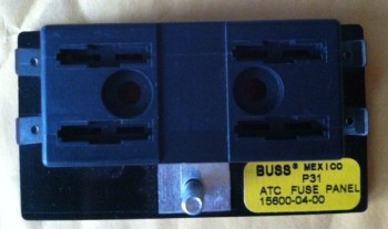
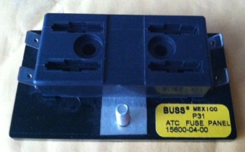
[Operational Note: Currently, this ATC Fuse Panel is no longer being used for my X-Bus. This X-Bus design was replaced with a DSub 9-Pin connector]
•••
28 May 2014 — Before I get into the specific subsystem wiring pages that I’ve completed over the past several days, I wanted to explain my requirement for creating subsystem diagrams for my Wire Book. Actually, in the spirit of efficiency, and because I think he explains it much more eloquently than I can, I blatantly stole an entry off of Nick Ugolini’s blog that helps expound upon the reasoning of why subsystem diagrams are invaluable tools to have in one’s toolkit when dealing with repairing, upgrading, troubleshooting and diagnosing electrical systems. Here’s Nick’s sage advice:
The wiring diagrams are absolutely CRITICAL to long term maintenance of the plane and they need to be as complete and clear as possible. After flying these planes for years, I find most of the maintenance issues in the future will mainly be wiring problems. Fixing a screw, bushing or engine component is quick and easy. Finding out why a light or radio stops working is really tough and almost impossible without a well-documented wiring schematic. The type of connectors, switches, plugs, type of crimper used, wire, etc should be of the highest quality possible, because it will bite you in the butt if you don’t pay really close attending to this critical aspect of the plane. Of all the work I am doing on the plane, I approach this area with the greatest concern and closest attention to detail possible. This is why it takes so much time and effort. I spent 3 hrs yesterday working on just 4 pages of wiring and I am still not done. I will probably have 30 or 40 drawings.
Some people approach the electrical draw from the aspect that you should put everything in an area on one page. An example is the power system should show all components and where they all go (charging, starting, lights, lines to the radios, etc). This is great for wiring the plane, but doesn’t help as much when you are trouble shooting a sub area of the larger system. Let’s say you are only working on the alternator part of this system.
I like drawing the areas out in sub systems. The alternator system is drawn separately from the starting system or the ignition system. In the future when you are trouble shooting problems with the charging system, it is MUCH easier to look at just the system of interest and visually see what is going on. You don’t have to separate it from a larger drawing with lots of other stuff on it. It makes wiring the plane more of a pain but is much easier to trace wires.
Anyone can wire a plane… it is not rocket science and is fairly easy to do. Run a wire from A to B and you are done. Easy. I have seen so many planes (certified and experimental) where if you ask the owner for a wiring diagram, you’ll get a blank stare. I have seen very few wiring diagrams and they were by obsessive compulsive engineer types who really knew the value of having one. Most builders just wing it.
-Nick Ugolini
So, with much agreement and in the spirit of Nick’s words, I’m pushing on in my attempt to complete these subsystem wiring diagram pages for my Wire Book. Since my last post on electrical diagrams I’ve completed the Fuel System, Alarm & Warning Systems, Starting System, and Long Wire Runs wiring diagrams.
Here is the fuel subsystem wiring diagram.
And here is the alarm & warning subsystems diagram.
I apologize if the pages look a little slanted, because they are. I’m using a Brother printer that is supposed to print 11×17 inch pages, and technically it does do that. However, it just doesn’t print the pages straight… or it does rarely let’s say. It sucks, but it was the only one I could grab in my limited time in the States before heading to the Middle East.
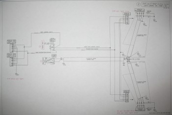
BTW, the long wiring runs is nothing more than a pictorial list of all the wiring runs between the nose/instrument panel area and the hell hole/firewall area so I can account for the amount of long wire purchases I may need to make if I don’t already have enough wire on hand.
Below is the updated list that I shared last week (again, green denotes completed or mature, yellow is currently being worked):
Z. Z-13/8 Electrical System
– Switch Configuration
1. Panel Components
2. Radio & audio system
3. Main Bus
4. Batt Bus
5. E-Bus
6. Nose Gear
7. Pitch & Roll Trim Systems
8. Lights: LDG, TAXI, NAV, STROBE
9. Engine Info Management
10. Fuel System
11. Cockpit Lighting
12. Landing Brake
13. Throttle Switches
14. Control Stick Wiring
15. Integrated Back-up Battery System
16. Alarm & Warning Systems
17. Charging System
18. Heater System
19. Electronic Ignition
20. P-Mag Ignition
21. Component Interconnects
22. Starting System
23. Panel, Battery & Avionics Grounds
24. Cockpit, Firewall & Engine Grounds
25. Heated Pitot Tube Wiring
26. Trio Autopilot
30. Long Wire Runs
•••
15 June 2014 — As I said in my last post, I’ve been really busy trying to get everything in order to relocate out of the Middle East back to the States. I’ll be visiting family on the west coast for a couple of weeks when I get back, so I’m trying to set-up all my travels once I get back as well.
I was able to do a fair amount of work on my Electrical Subsystem Diagrams, and I added a few more to the list. Unfortunately I haven’t had time to take any pics of them. Here is the new updated list nonetheless:
Z. Z-13/8 Electrical System
– Switch Configuration
1. Panel Components
1.1 Panel Components Power
2. Radio & audio system
3. Main Bus
4. Batt Bus
5. E-Bus
6. Nose Gear
7. Pitch & Roll Trim Systems
8. Lights: LDG, TAXI, NAV, STROBE
9. Engine Info Management
10. Fuel System
11. Cockpit Lighting
12. Landing Brake
13. Throttle Switches
14. Control Stick Wiring
15. Integrated Back-up Battery System
16. Alarm & Warning Systems
17. Charging System
18. Heater System
19. Electronic Ignition
20. P-Mag Ignition
21. Component Connections
22. Starting System
23. Panel, Battery & Avionics Grounds
24. Cockpit, Firewall & Engine Grounds
25. Heated Pitot Tube
26. Trio Autopilot
27. ELT
28. Connectors/Pin IDs
30. Long Wire Runs
This will probably be my last update on these Electrical System Subsystems for a while. I should get back into the swing of things on the build starting early to mid-August when I’m settled back in my house in Northern Virginia.
•••
12 July 2016 — Lately I have been working on my electrical system . . . a lot! I’ve probably put in a good 30 hours on my electrical system over the past 3-5 days.
Why, you ask?! Especially when the plane is not near the point that it needs such detailed electrical diagrams! Well . . . I’d argue otherwise. Having finally got my other house off my plate –it closed last week!– I am getting ready to do another gargantuan push on the build. I have no other real detractors at this point and I am preparing to dive in with all I’ve got. So, besides simply wanting to clear up a few nagging issues in my electrical design, especially before bringing any more on board, I wanted to get my electrical system design and documentation as up to speed as possible.
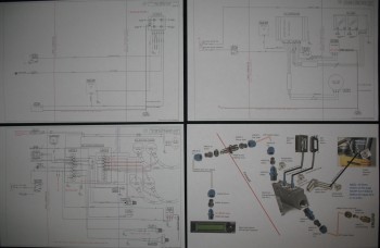
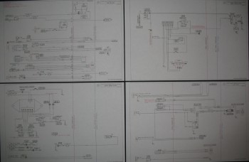
Below is the end result of my efforts over the last few days.
Here are the individual diagram pages for each subsystem. To be clear, these are ONLY the ones that I’ve updated over the past week! There are still about 10 more that need to be tweaked, refined and updated.
An even closer shot . . .

My focusing on the electrical system was some what of a result of 3 things converging on me at once.
First, my buddy Marco bought a beautiful Long-EZ to fly while he finishes up his build. Stemming from discussions on his new plane, our in-depth mind-melding on switchology, control/switch ergonomics and safety really got me diving deeper into a topic that I had been bantering around in my mind for quite some time.
Next, Grand Rapids Technologies debuted their 8.4″ HXr EFIS at Sun ‘N Fun in April. DONE!!!!!! This is exactly what I have been waiting for FOR YEARS!!! The right size with the right features to drive my components in meeting my design goals. With this in hand, combined with a much more refined picture of my switchology, I set forth to conquer any of the major remaining design daemons in my architecture.
Lastly, I’m just bone tired. I had less than a week to clean a very messy house that my tenants left me, and I had a number of repairs on top of that. I was working 13-16 hour days for almost a week, and I am just exhausted. Working on the electrical system lets me rest a little physically as I recharge to tackle this beast! Hoo-ah!
(Below is a pic of my Master Electrical System Diagram, which has been modified over a dozen times in the past month alone!)
Over the past couple of days I’ve been on the phone with EFII, GRT, B&C, Trio, TCW, and a few others confirming my architecture design in the areas that incorporate their respective products. I also confirmed some key system design features in a discussion with Bob Nuckolls (author of The AeroElectric Connection). In short, I’ve been able to clear up a number of nagging design issues, streamline my system and really make a number of my electrical design goals a reality… There are a lot of them, so I’ll discuss them individually in-depth as I incorporate them into the build.
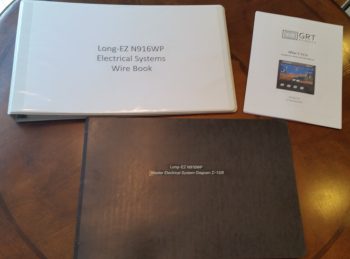
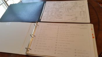
Finally, I think I mentioned before that I took a bit of time to really go through my documentation on hand and clear out all the junk, archive most of the gee-whiz stuff and get it fairly organized into binders and work folders. I had the same idea for my electrical system design documents as well, considering I haven’t really had any of them consolidated into a meaningful system until today. I finally took the time to build electrical system binders to incorporate ALL the electrical system wire books, system diagrams, etc. into 2 binders, shown above, and I even constructed a table of contents/index. I have to say by the time I was done I felt a huge sense of relief knowing that my electrical system is looking really, really good as I head into one of the final build surges on my Long-EZ project!
•••
14 July 2016 — I’ve spent a few hours over the last couple of days updating my Control Stick Switches wiring diagram (#14) which institutes a major redesign on my control stick switchology. This is of course is the first draft with all the foundational components in place. It still needs much refining. For example, I still need to design & emplace a switch into the mix that will allow me to disable the GIB control stick switches for those times when I’m hauling kids (or Marco!) in the back, who may be just a tad too inquisitive and want to get handsy with the buttons! (sorry for the poor pic quality…)
•••
21 July 2016 — Over the past few days I’ve pretty much finalized all I can with my electrical system planning at this time. I would hazard a guess that over the past couple of months I’ve moved the “finish” dial on my electrical system design & documentation from the 89-93% range to the 96-97% complete range. There are still a few more admin things I need to finish, and depending on any future changes in vendor-mandated installation requirements on my respective components, I’ve pretty much got the design dialed in to the point where I can implement the electrical system plan where permitted from here on out as I build. I do have a couple of switchology decisions to make, but those won’t come until I mock up the panel and play around in a simulator-type setting while making airplane noises.
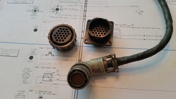
Moreover, I met another design milestone by creating wiring diagram 13 showing all the wiring for the 6 throttle handle-mounted switches. Since I’m making the throttle handle removable I’ll be running all the wires through a 24-pin AMP CPC connector–the same style connector that I used on the nose gear actuator connectors where I swapped out the stock Molex connectors. On the throttle handle I’ll be wiring all the switches with new wiring and swapping out the old stock circular Amphenol Mil-Spec connector with the much lighter and cheaper TE Connectivity AMP CPC connectors.
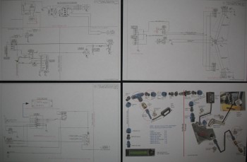
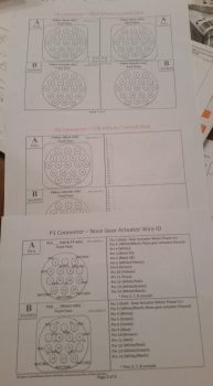
With my throttle switches clearly identified, and the wiring to & from each switch, I could then marry up my initial throttle switch diagram with the 24-pin AMP CPC connector and finalize the throttle handle’s P4 connector pinout diagram. I have all my multi-pin circular connectors detailed in a PowerPoint slide deck (it just evolved that way). And since I currently have seven connectors on the aircraft (P1-P7), I obviously need a diagram for each connector. Unfortunately, I hadn’t created all the diagrams, so down another rabbit hole I went for a couple of hours to finish all the templates for all the circular connector pinout diagrams, as you can see in the pic below.
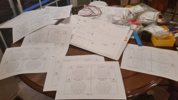
Now, each connector pair gets 2 pages detailing the pin assignments. The first page (top of the 3 pages in the pic below) details the general information about each connector: number of pins, part numbers, mounting flange (if present), hole number schema, pins, sockets, and standard vs reverse sex connector. The second/back page (middle & bottom in pic below, with bottom page info populated) shows the detailed pinout for each connector side, with wire colors and wire function/connectivity. I of course finalized populating all this information for each side of the P4 throttle handle switches connector.
Alright, moving on.
I currently have everything either on hand or on order for my electrical system. As I did a couple of years ago, I’ve included a rundown below of all my electrical system diagrams (wire book) up to this point. As you can see, I have a few more systems to figure out, but nearly all of the really critical stuff is complete. As for the Main, Battery and E- Busses, I won’t diagram those out until all my other system designs are completed and installed.
0. Index Page
Z. Z-13/8 Electrical System
A. Switches, Circuit Breakers & LEDs
.99 Grounding Busses
1. Panel Components
2. Radio & audio system
3. Panel Power
4. Electrical System Components Location Diagram
5. Aircraft Wire Labeling Sectors Diagram
6. Nose Gear
7. Pitch & Roll Trim Systems
8. Lights: LDG, TAXI, NAV, STROBE
9. Engine Info Management
10. Fuel System
11. Cockpit Lighting
12. Landing Brake
13. Throttle Handle Switches
14. Control Stick Switches
15. Integrated Backup Battery System & X-Bus
16. Alarm & Warning Systems
17. Charging System
18. AG6 Warning Annunciators
19. Electronic Ignition
20. P-Mag Ignition
21. Heater System
22. Starting System
23. ELT
24. Heated Pitot Tube
25. Trio Autopilot
27. Main Bus
28. Battery Bus
29. E-Bus
30. Long Wire Runs
•••
6 September 2016 — After getting all the first half of the day’s miscellaneous tasks out of the way, I started in on something I’ve been trying to knock out over the past few days. You see, Marco has been diligently working on the pitot tube wiring system for our Long-EZs, and I haven’t been the best teammate in assisting with the effort (See Marco’s latest post regarding the pitot tube electronics on his blog). Moreover, a number of days ago Marco asked if I could draft up the wiring diagram (#24) for the Heated Pitot Tube Electronics. Thus, a main goal I had today was to get this sucker knocked out, which I did below. Of course there will be a bunch more mods to this diagram as we move forward, but as of right now we have a good baseline schematic for the pitot tube electronics!
Here’s an updated list showing the Electrical System Wiring Diagram status:
0. Index Page
Z. Z-13/8 Electrical System
A. Switches, Circuit Breakers & LEDs
.99 Grounding Busses
1. Panel Components
2. Radio & audio system
3. Panel Power
4. Electrical System Components Location Diagram
5. Aircraft Wire Labeling Sectors Diagram
6. Nose Gear
7. Pitch & Roll Trim Systems
8. Lights: LDG, TAXI, NAV, STROBE
9. Engine Info Management
10. Fuel System
11. Cockpit Lighting
12. Landing Brake
13. Throttle Handle Switches
14. Control Stick Switches
15. Integrated Backup Battery System & X-Bus
16. Alarm & Warning Systems
17. Charging System
18. AG6 Warning Annunciators
19. Electronic Ignition
20. P-Mag Ignition
21. Heater System
22. Starting System
23. ELT
24. Heated Pitot Tube
25. Trio Autopilot
27. Main Bus
28. Battery Bus
29. E-Bus
30. Long Wire Runs
•••
17 November 2016 — I spoke at length with Bob from TCW Technologies twice today to finalize my Integrated Backup Battery System (IBBS) circuit configuration. While reviewing the installation manual I ran into some questions on the Pass Thru pins on the IBBS. Changing over to the X-Bus configuration and adding a switch apparently jumbled up my circuitry a bit and Bob was nice enough to walk me through how to get back on the straight and narrow path.
In short, at a minimum I eliminated another switch off the panel and it looks promising that I’ll be replacing the 8-port ATC fuse panel that is the X-Bus, for a 9-pin D-Sub connector, thus saving weight and of course space on the Triparagon. With a total rework of the IBBS wiring, I wanted to get my notes transferred over into reality on the IBBS/X-Bus wiring diagram. In addition, as I worked to organize & update the wiring schemes in my electrical system I finally had enough of tracking a bunch of info on a clipboard, so I ended up creating 2 new diagrams that I’ve long since had on my diagram list:
18. AG6 Annunciators
27. Main Power Buss
Here’s the latest updated list showing the Electrical System Wiring Diagram status:
0. Index Page
Z. Z-13/8 Electrical System
A. Switches, Circuit Breakers & LEDs
.99 Grounding Busses
1. Panel Components
2. Radio & audio system
3. Panel Power
4. Electrical System Components Location Diagram
5. Aircraft Wire Labeling Sectors Diagram
6. Nose Gear
7. Pitch & Roll Trim Systems
8. Lights: LDG, TAXI, NAV, STROBE
9. Engine Info Management
10. Fuel System
11. Cockpit Lighting
12. Landing Brake
13. Throttle Handle Switches
14. Control Stick Switches
15. Integrated Backup Battery System & X-Bus
16. Alarm & Warning Systems
17. Charging System
18. AG6 Warning Annunciators
19. Electronic Ignition
20. P-Mag Ignition
21. Heater System
22. Starting System
23. ELT
24. Heated Pitot Tube
25. Trio Autopilot
27. Main Bus
28. Battery Bus
29. E-Bus
30. Long Wire Runs
•••
28 June 2017 — Today I started off working for a couple of hours updating 5 electrical diagrams:
- A. Switches, Breakers & Panel Lights
- .99 Grounding Busses
- 4. Electrical System Components Map
- 10. Fuel System
- 11. Cockpit Lighting
•••
13 August 2017 — As I was preparing to install the sump low fuel level sensors, I needed to create wire labels for both the sensor wires and the GIB LED floor lighting wires that are located in the sensor covers. Besides just wanting to keep my wires identified, in this situation it’s even more vital since all these wires are hidden away for the first 12-18″ and ascertaining what wires go to what would be much more difficult without wire IDs.
With all the obvious effort I’ve done on my electrical system, this little ditty here shows how extensive the task is: As I was listing out my wire labels to print I realized that I didn’t have enough consolidated information on exactly what component power wires connected to my power busses at which tabs. With the addition of a few extra unexpected electrical components over the past 6 months –including these low fuel sensors– it’s really too easy to lose sight of exactly what power wires feed from what buss, and exactly what tab a specific wire may get connected to.
Thus, yes, another unintended and unexpected task reared its head… I determined that my sheet of notebook paper with the Main, Endurance and Battery power buss connections listed on it just wasn’t enough. I needed it in electronic format as a worksheet in my electrical system spreadsheet, so I made that happen. Then I spent a few hours inventorying every instance and every wire that connects to a power buss, including each buss’s threaded feed stud.
Besides the information listed on my tattered notebook sheet, I did an accounting for the already labeled tabs on the physical ATC fuse busses. I then went through literally every wiring diagram to account for every listed power buss connection in the diagrams. I then went through my components list to ensure that the power feed for every electrical component going into the plane was accounted for. Through all this I found some discrepancies in the required fuse sizes. Finally, with a complete accounting of all my buss power connections I was able to reorganize some connections on the respective buss tabs.
•••
9 September 2017 — I started out today doing some electrical system housekeeping. I keep a listing of all my electrical system components and their 2-digit identifier code used in my wiring label scheme. Well, over the past 9 months I’ve had some major changes to some of the electrical subsystems and while I’ve kept up with the actual wiring design, the code tracking has room for improvement.
I updated my database and printed off a bunch of 2-digit ID labels and tracked down the stuff that needed labeling. I’ve also rewickered a lot of lighting circuits and some switches, so I updated those and my switch tracking diagram as well.
•••
30 September 2016 — Today I did a fair amount of research on the heating system. That rolled into updating a few wiring diagrams to reflect the updated electrical requirements, which included: the removal of the GIB Infinity control stick, resulting in the need to update the switch diagram, and of course updating the newly created Heating System diagram (these 3 are shown below).
•••
7 January 2018 — I spent over 5 hours today scrubbing & updating every wiring system diagram I have on hand. I figure that if all goes according to plan that this will be the last winter I have before my first flight to knock out all this nitnoy stuff…. again, much of it that I haven’t gone over in quite a while.
•••