
Chapter 22 – Physical Instrument Panel
This page discusses the design and making of the physical instrument panel versus layout of the instruments, avionics, switches, etc.
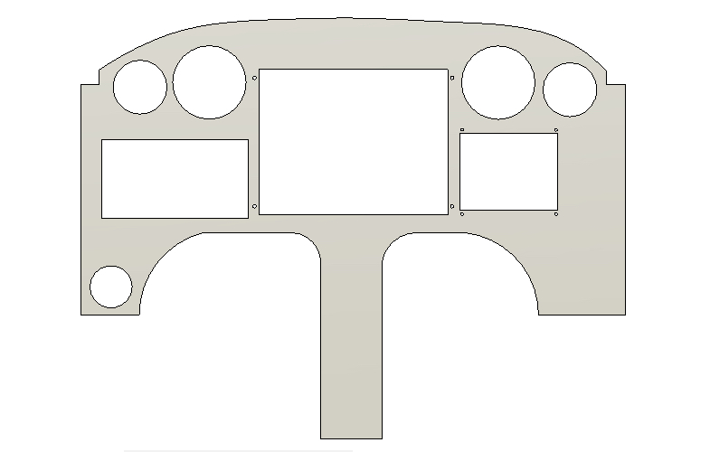
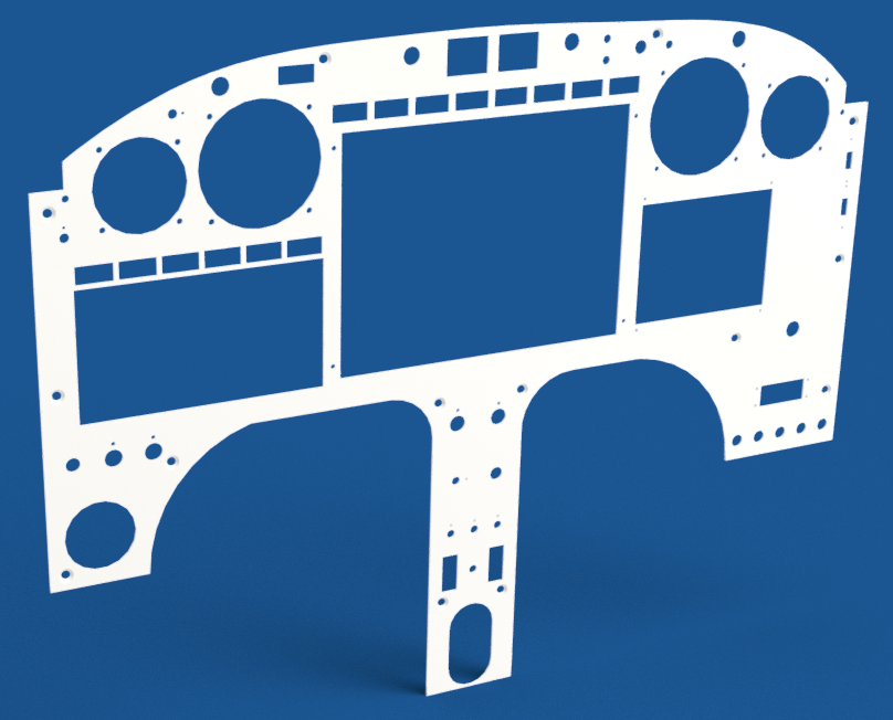
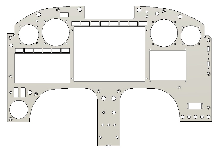
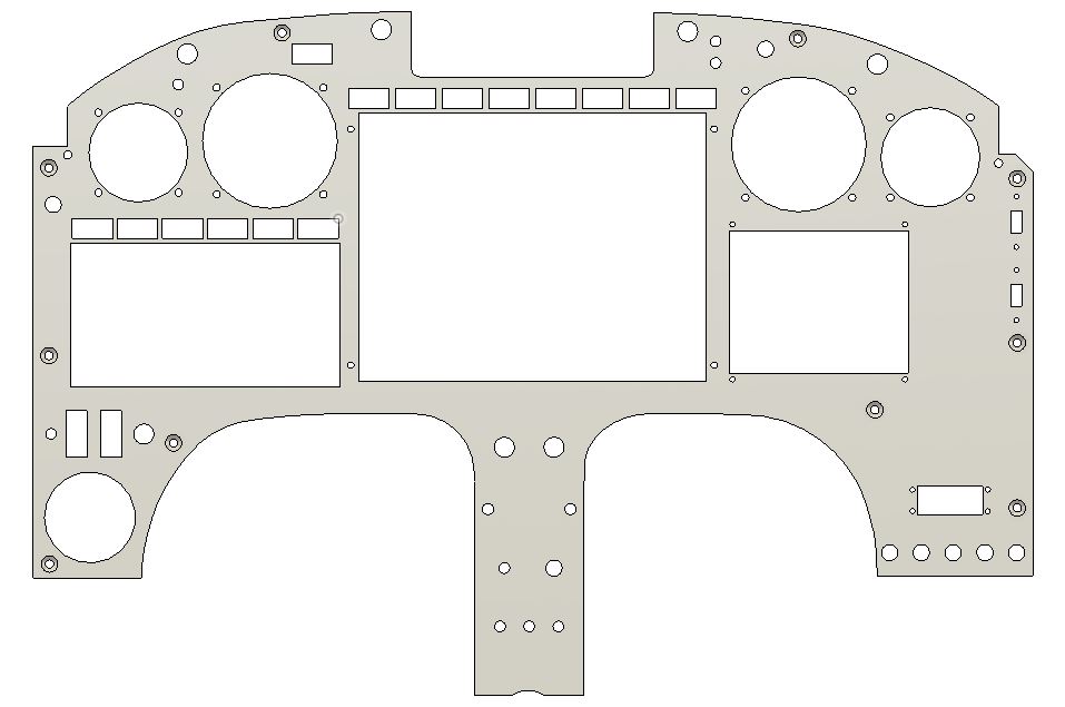
14 February 2019 — Today I set my sights on drawing up the Instrument Panel in Fusion 360 CAD. I don’t have the exact dimensions on-hand since my project is down south, but I can always easily tweak those numbers later. In addition, I simply started out by placing and “cutting out” the holes for the major panel avionics and instruments. As time goes on I’ll tweak this drawing to account for switches, circuit breakers, etc.
•••
16 February 2019 — Continuing on with my CAD blitz as I wait out the final stages of being sick, as I noted in my last blog post I undertook a significant item on my to-draw list:
the Instrument Panel.
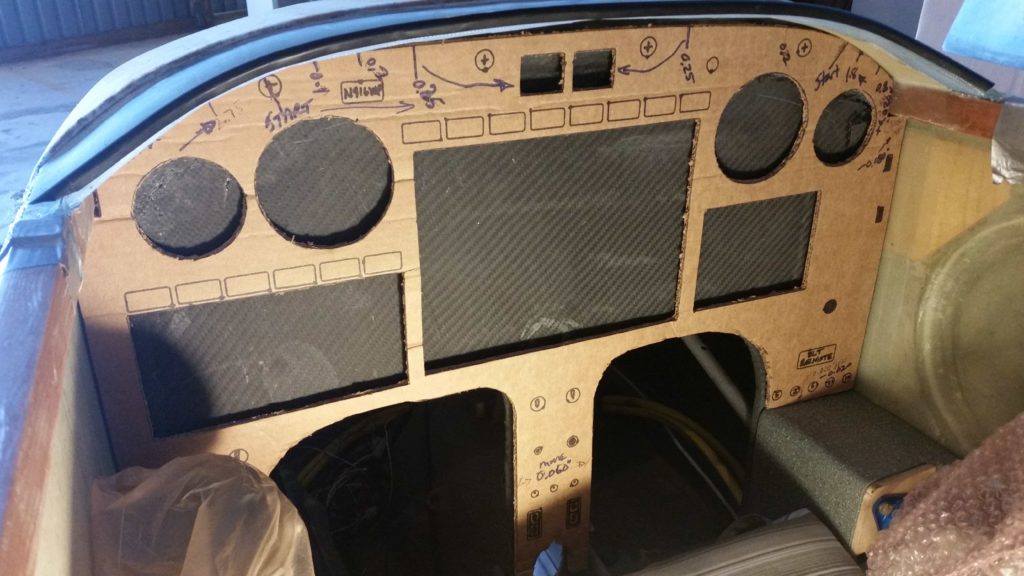
This has been a multi-day endeavor that in many regards is just a best-guess attempt at getting the numbers right since [again] I don’t have the panel mockup in hand. Moreover, I based the major panel dimensions off of the cardboard mockup that I made up in 2012 and used extensively while both in Tampa, FL and Qatar as I assessed various panel components/configurations.
Not a big deal of course since it’s EZ-PZ to move components around on the panel in CAD. The bigger deal is getting the component holes sketched onto the panel in the first place. To take the drama up even another notch: the biggest deal is the painstaking detail of ensuring all the components are aligned correctly with their mounting holes and the myriad of required clearances —just enough with this tight space— with each other.
In all likelihood –considering all the major avionics are currently dialed in with each other– the most significant changes from here on out will be on the order of moving the entire avionics section a tick left or right, and a smidge up or down. Switch locations and spacing, as well as entire rows of switches, will be highly subject to tweaking as well.
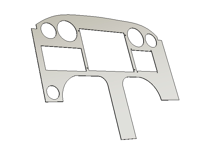
That all being said, here’s another bit fancier version that I rendered up.
•••
5 March 2019 — After departing NC on this last trip to clear out my #3 storage unit and consolidate nearly all the airplane build stuff in the hangar, I headed up to Virginia Beach to spend a couple of days with Marco and Gina.
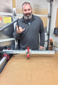
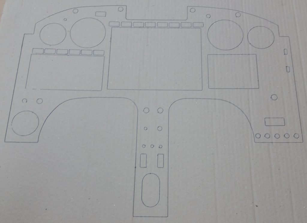
While at Marco’s, I updated my Instrument Panel CAD diagram with all the dimensions I had taken off the actual panel while down in NC. With Marco’s help, I then shared the CAD file to a shared online folder and he was then able to convert it into CAM to be drawn out on his plasma cutting table with a Sharpie onto cardboard.
This may seem like some underutilization of a fairly expensive plasma cutter to merely use it as a plotter, but not only did it test & confirm some limit capabilities of Marco’s plasma cutting table (better than we initially thought), but obviously it will allow me to cut out the cardboard panel, test it in the actual airplane, and then make any required tweaks if need be before we do an actual plasma cutout of the panel with actual expensive aluminum.
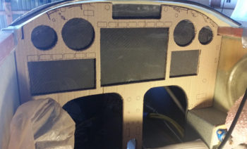
In fact, the pics of the crazy bearded guy below (me!) is with plotted panel version #1, which afterwards I realized that I had forgotten to update some dimensions I had gathered relating to the panel’s upper corner longeron notches . . .
Although I’d like to say it was fairly easy to update the CAD file to redraw the dimensions on the panel longeron notches –and subsequently the top panel contour– it actually did take a bit of drama-filled machinations to get it done. But, with Marco’s help I learned a few new tricks regarding Fusion 360 and was able to update the panel drawing to the correct dimensions.
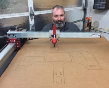
We then embarked on plotting out Instrument Panel version #2 on Marco’s plasma cutter with no hiccups.
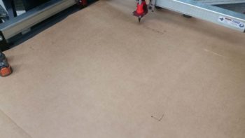
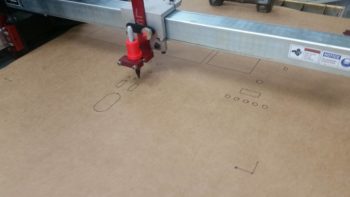
In fact, I took a short video of the last little bit of the panel plotting effort on the Plasma Cutting table. We didn’t film the entire event since to draw the separate circles and rectangles in the panel we had to lift the Sharpie up slightly in its holder (which Marco cleverly designed and 3D printed) after each drawn component to allow the assembly to relocate to the new spot that the next component would be drawn, then slide the Sharpie down in contact with the cardboard.
This pen lift/drop cycle is shown in the video, as is the entire drawing of the Instrument Panel perimeter.
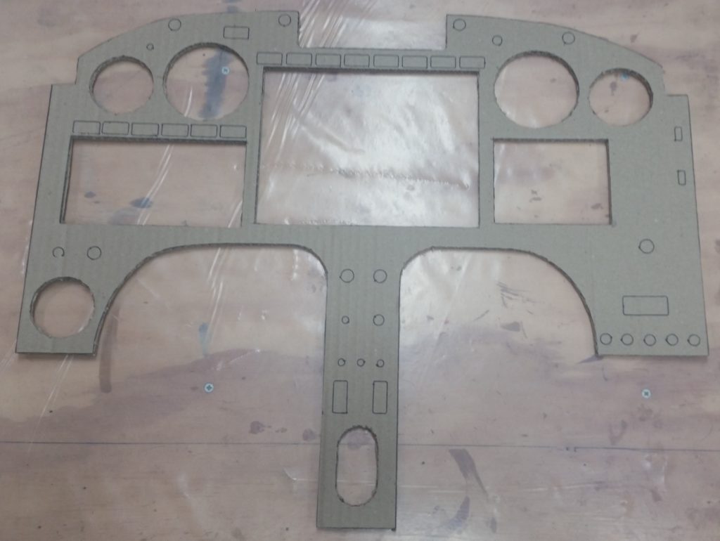
After the instrument panel plotting was done on Marco’s plasma cutting table, I then labeled the components on the cardboard to grab this shot here. Most of the larger component holes will get cut out, which I’ll show in a subsequent blog post.
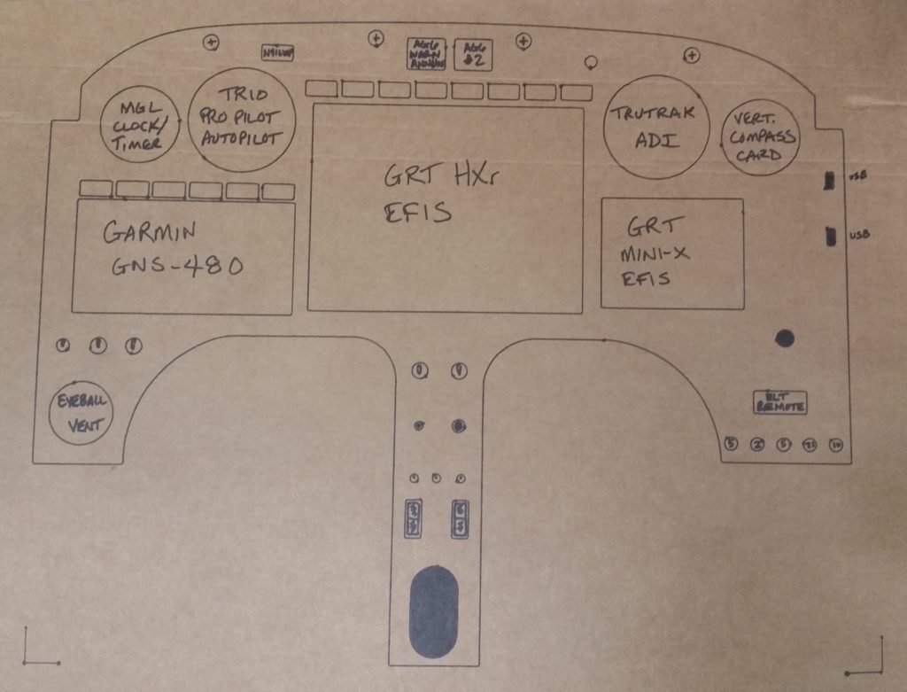
I’m extremely pleased with how the cardboard panel mockup came out, and am excited about dialing in the panel CAD drawing to enable Marco and I to plasma cut my panel out of a piece of aluminum. I will say that Marco and I (and a few others) are discussing the pros and cons of 2024 vs 6061 and what thickness the panel should be (0.063″ to 0.090″).
•••
9 March 2019 — In one of our conversations my buddy Marco asked if I had cut out the panel yet, so I sent I sent him this . . . Yep! (yuk-yuk)
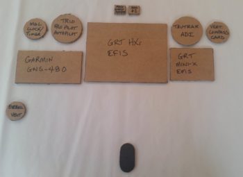
Of course this is the cardboard panel cutout… that I drew up in Fusion 360 CAD and then Marco precisely drew out for me on cardboard using his plasma cutting machine as a high-end plotter.
As a point of note, I’ve made a final decision to go with 0.090″ thick 6061T6 as my panel material.

•••
10 March 2019 — After all these years I finally made a decision to use 0.090″ 6061T6 aluminum to cut my instrument panel out of. Using this specific aluminum offers 2 benefits over the 0.063″ 2024 aluminum that I had been planning on using for quite some time.
First off, plasma cutting 6061 is cleaner than 2024 since 6061 is better at rejecting heat (6061 can be welded, whereas 2024 cannot). Also, a thicker panel has less tendency to warp during heat-producing operations such as plasma cutting.
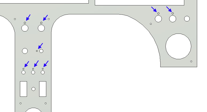
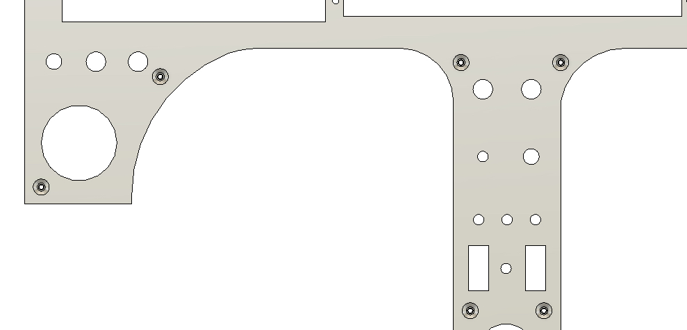
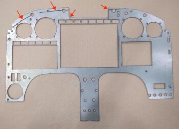
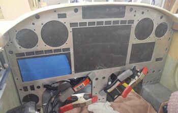
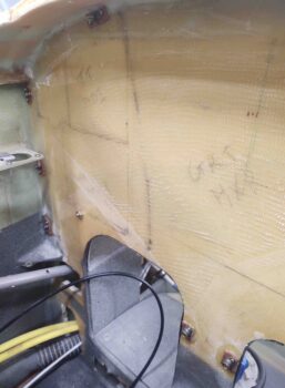
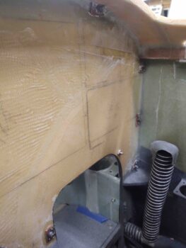
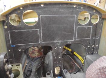
Next, the 0.090″ thickness will allow hiding the panel switches’ anti-rotation keyway holes, which coincidentally need to be 0.063″ deep. Below, the blue arrows denote 8 of the 10 anti-rotation keyways (on the panel backside) –which were once all through-panel holes– that were removed from the front face of the instrument panel once I thickened the panel from 0.063″ to 0.090″.
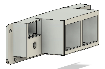
Below is a more “3D view” to better see the switch anti-rotation keyway holes at an angle, again, on the backside of the panel.
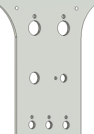
Meanwhile, over on the front side of the panel: no visible switch anti-rotation keyway holes!
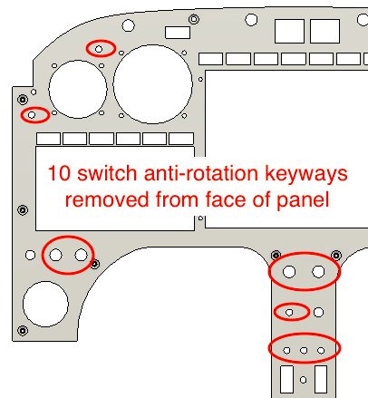
Here is just a quick annotation of all the anti-rotation keyway holes that I was able to remove (hide) off the panel front by going with the thicker 0.090″ 6061 aluminum panel.
•••
22 March 2019 — Today I checked the fit of my cardboard mockup of the panel that Marco printed out on his plasma cutter. I found a number of areas where the dimensions need to be tweaked, especially around the leg holes and along the top edge, the latter being around 1/4″ short for a good 4 or so inches each side of the center line.
So, it’s literally back to the drawing board for the panel.
•••
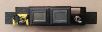
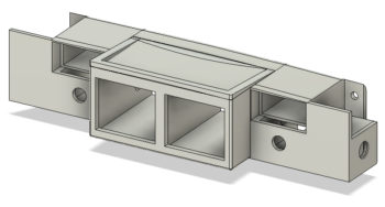
26 March 2019 — I’m not sure exactly when I came up with the idea, but over the last couple of days –while updating the Instrument Panel CAD drawing– I decided to move forward with aPanel Warning Annunciator Cluster Sub-panel that would include the major panel components that I would need in case of most emergencies: including notification via the pair of AG6 Warning Annunciators and possible fix actions via the Gear Automatic Extension System/Emergency Gear Down Switch and the Backup Alternator (SD-8)/E-Bus activation switch.
In addition, I would move the “AEX ENGAGED” notification Korey LED light from the row just above the HXr EFIS to this sub-panel cluster as well. That would, in turn, allow me to use that empty light position to add a “RAM Air Open” indicator light to give me positive feedback that my RAM air butterfly valve was in fact in the open position…. good to verify when descending below 3000 feet for low level flight ops, landing, etc.
Finally, conspicuously not added to this group is the Alt-Static Source switch, which I will leave in a different spot on the panel.
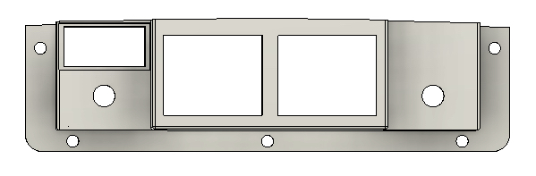
I then spent a few hours creating and then extracting this model drawing from the Instrument Panel CAD drawing…. thus, not only does it share the same DNA, but more importantly the same top curvature and centerline. This will allow me to better appropriately notch the panel for clearance of this cluster if I end up going this route.
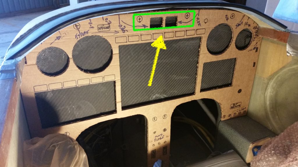
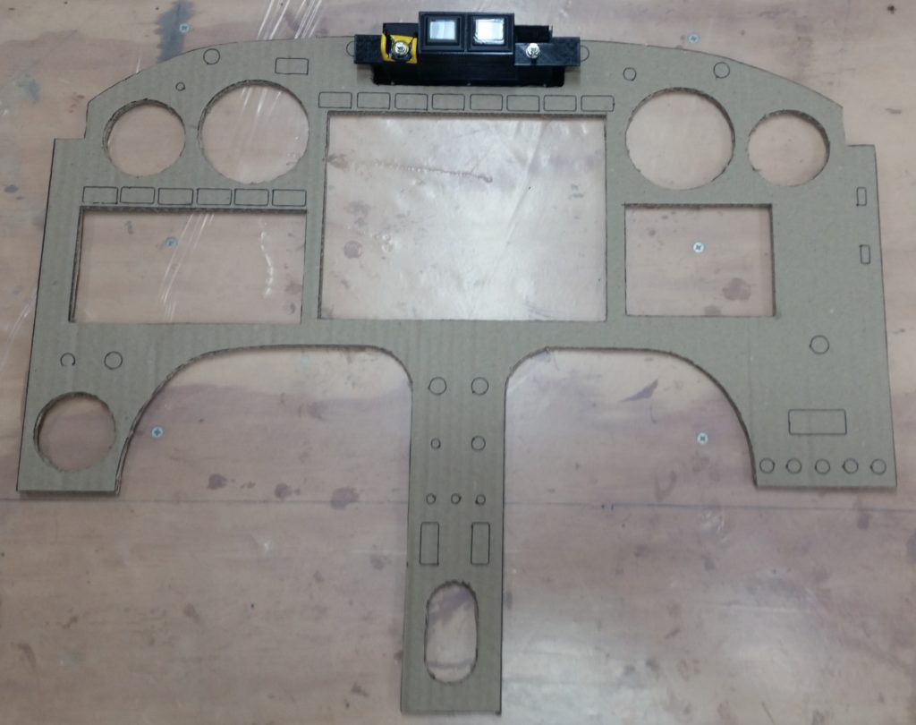
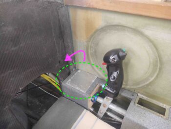
Just in case you’re scratching your head wondering what the heck I’m on about (probably not unusual!), I’ve depicted a rough outline of this Panel Warning Annunciation Cluster overlaid on a pic of the panel.
I should note specifically that I have 2 main driving reasons for incorporating such a warning annunciation cluster: First, I want to ensure unimpeded visibility of the AG6 warning annunciators by literally putting them “in my face,” and by extruding the mount for the AG6’s rearward and placing them just under the aft edge of the glare shield gets them in that “in my face” position.
Second, by consolidating the 2 key emergency-specific electrical switches in this cluster, I both better organize the panel functionally and concurrently clean up the panel of extraneous switches placed in a somewhat willy-nilly fashion.
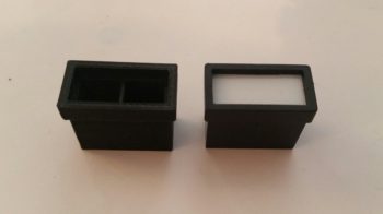
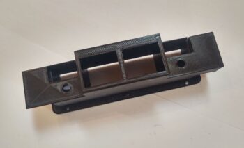
Upon arriving home this evening from NC, I fired up my trusty 3D printer and made a very fast, rough “proof of concept” 3D print of this warning annunciation cluster.
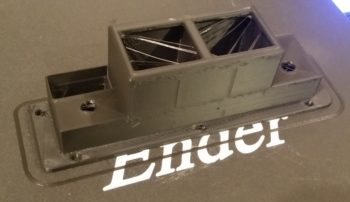
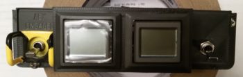
As I was leaving out from NC, I stopped off at the hangar to scavenge the AG6 warning annunciator display/buttons, “AEX ENGAGED” Korey indicator light, the emergency gear down switch guard and some mini-toggle switches.
I then used all the above to populate my freshly 3D printed warning annunciator cluster sub-panel.
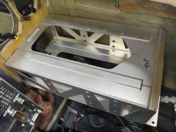
Here’s a top view, which would actually never be seen if this sub-panel were mounted in the airplane since the top abuts the underside of the glare shield.
Moreover, the pic below does show a change that I quickly realized I needed to make on this model, which was to increase the “height” (technically depth) of the switch stepped platforms moving aft by 0.15″. This will serve to get the aft edge of the switch guards (there will be one on the right side switch as well) closer aligned with the AG6 annunciator faces.
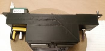
This sub-panel will be mounted to the top center of the panel via 5x #6 screws, which I have a couple installed to test fit the screw hole sizes.
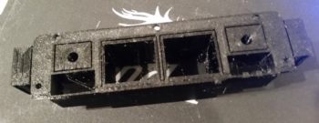
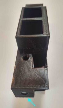
Here’s a shot of the backside of the sub-panel, showing AG6 module, switch, and Korey light position, configuration and clearance.
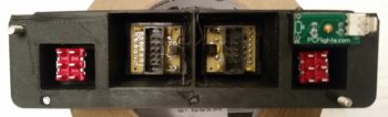
With space tight, and to keep this cluster as compact as possible, I incorporated the “AEX ENGAGED” Korey indicator light so that it is actually embedded into the body of the sub-panel. Moreover, the switch guard of the AEX OFF/ON and Emergency Gear Extend switch slightly overlaps the bottom edge of the Korey indicator light.
So far I’m very happy with how this Panel Warning Annunciator Cluster Sub-panel has turned out and I’m excited to test fit it in the actual airplane.
•••
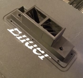
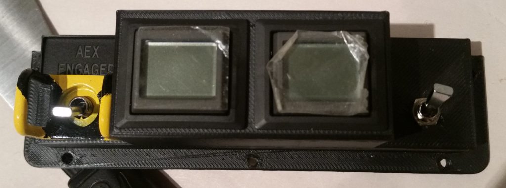
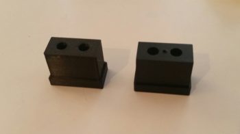
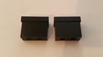
29 March 2019 — Today I kicked off a 5+ hour long PETG (my first with this black filament) of the Warning Annunciation Subpanel Version 2.
Here it is after it finished printing. Again, PETG is known for being stringy, and the label fits since it is quite that.
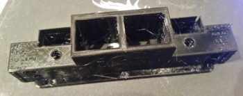
One reason why this particular 3D print took so long is that there were a considerable number of supports printed to ensure the print came out straight and true. The blocks on each end, the rectangles containing the holes and the inset linings of the middle squares were all full height supports that I removed.
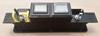
Here’s the part a bit later, after I removed all the supports, cleaned it up a bit and then swapped the components out from Version 1 to this version.
As you can see, I added tabs to each side specifically to be able to add labels to the switches. The raised-letter printing didn’t come out so great, although I will try to apply some white paint to see how bad/good it actually looks.
My thought though is to simply increase the height of these side tabs, and then order some sticker labels that I will then attach to each tab. So far I’ve noted about 7 different changes that need to be made to Version 2 to create a new Version 3 down the line.
•••
17 April 2019 — While visiting Marco at his house I spent well over an hour updating the remaining tweaks I had noted that my panel drawing required to fit properly as on overlay onto the existing composite panel structure. The main areas that are difficult to dial in is the top curve and the leg hole curves, but after a bit I had them as close to what I wanted and was ready to print.
It took a bit more time for Marco to convert the Fusion 360 CAD generated G-code into a usable format for us since we have to have the plasma cutter stop after each drawn component so that we can lift the Sharpie, then position the print (plasma cutting) head to then drop the pen and draw the next component.
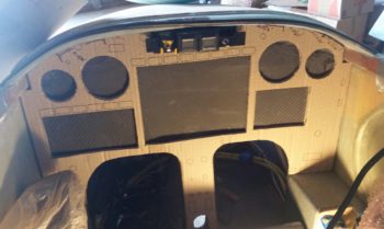
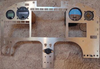
Just as before on panel version 1, it was no real difficult feat and after a short bit of time Voila! We had panel version 2’s mockup drawn up on a large piece of cardboard.
I then spent another half hour cutting out the panel just before me, Marco, Gina, Chris Cleaver and his wife Mary Kay went out for some delicious fish tacos down near the Virginia Beach boardwalk.
Upon returning back to Marco’s I then set the warning annunciator sub-panel in place in the notch I had created in the upper centerline area of the instrument panel. The fit was good, although I may need to scale down the gap just a touch between the main panel and sub-panel.
•••
19 April 2019 — Today I was able to test fit version 2 of my instrument panel cardboard mockup. I’ll reiterate that I feel that it would be infinitely easier to simply trace out, cut a panel by hand and then mount it than it is to constantly fiddle with drawing up the instrument panel in CAD to fit the existing composite panel structure . . . again, especially at the top curve and leg cutout curves.
However, since I do have a bit of time available to do draw up and check the panel –since I’m still in the amazingly protracted process of moving down to NC– in the long run it will be so much better to have a match-fit panel available in CAD if I ever want to do any panel upgrades, improvements or overhauls. The ability to plan and fit on “paper” in CAD will make any future (and has definitely been proven during current planning machinations…) upgrades or additions much, much easier to handle.
Clearly the major change between panel version 1 and panel version 2 is the notch made top centerline to incorporate the warning annunciator sub-panel. Since we didn’t print out all the switch positions with the marker, it’s not easily identifiable to note that there are a couple fewer switches on the panel.
Panel version 2 fit much better than version 1, most significantly at the leg holes. The top curve still offered up a few challenges, but that should be easily remedied but just one slight shaving in the upper left corner and lopping off about 0.030″ on the bottom corners just above each arm rest.
In addition, I do plan on moving ALL the instruments and avionics up about 0.15″ to create a wider crosspiece just above the leg holes.
•••
5 June 2019 — On my latest trip to North Carolina I was able to stop by Marco’s on the way down, where Marco and I then printed out the latest cardboard version (#3) of my instrument panel before I left for my NC hangar.
After unloading all the hangar stuff from my load I then quickly cut out the perimeter of the cardboard panel mockup to test fit it in place. Note that I didn’t cut out any of the internal area to ensure the panel was as strong and rigid as possible for the test fit.
The cardboard test panel fit well, but it still needs just a couple minor tweaks: shaving off about 0.020″ on the upper left edge and also shaving about 0.050″ off each vertical edge. I also need to assess clearance between the lower corners on each side of the panel with the respective armrests and switches.

•••
12 June 2019 — I was quite tired from this last trip so I decided to “take the day off” today, take it a bit EZ and do some CAD work.
I started off by updating my Warning Annunciation Sub-panel to bring the face of it further out from the panel. I then 3D printed the new version 4.
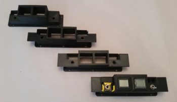
To show you the design machinations, here’s a shot of all 4 variants so far. As you’ll see later below, I’m now on version 5.
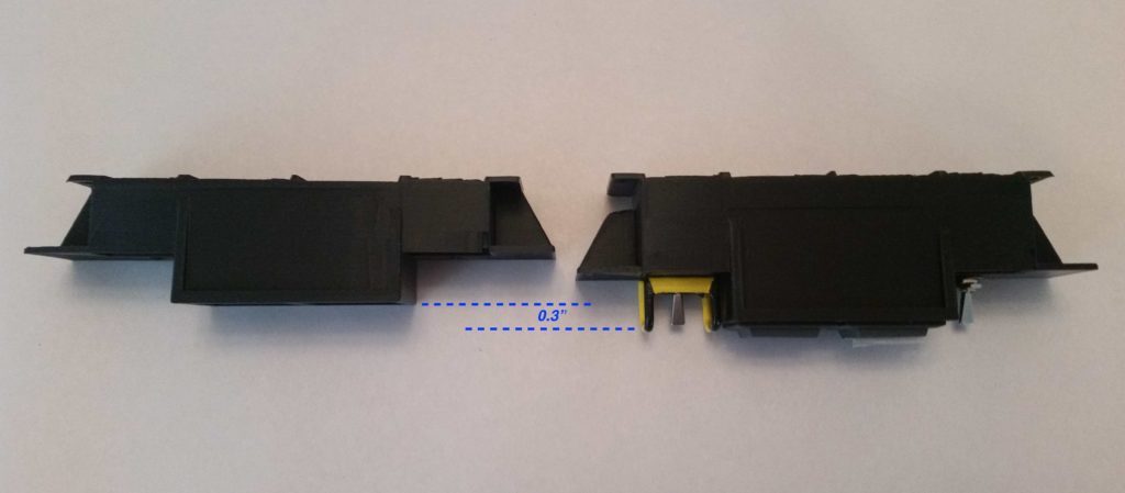
The reason for this new added sub-panel depth was that I checked the visibility of the warning sub-panel while I was sitting in the cockpit with the canopy closed (probably a good thing to check eh? …. actual flight configuration?!) and realized that the top edges of the AG6s were obscured from the canopy skirt and the angle that I view it from. Also the top 2/3rds of the embedded Korry indicator lights were obscured as well.
So I added 0.3″ to the back side of the sub-panel to bring it out to the very edge of the glare shield so I could see it fully with the canopy closed. Now only less than the top 1/3 of the Korry indicator lights will be obscured while the AG6s will be fully visible.
Here’s a top-down view showing the depth difference between version 3 and version 4.
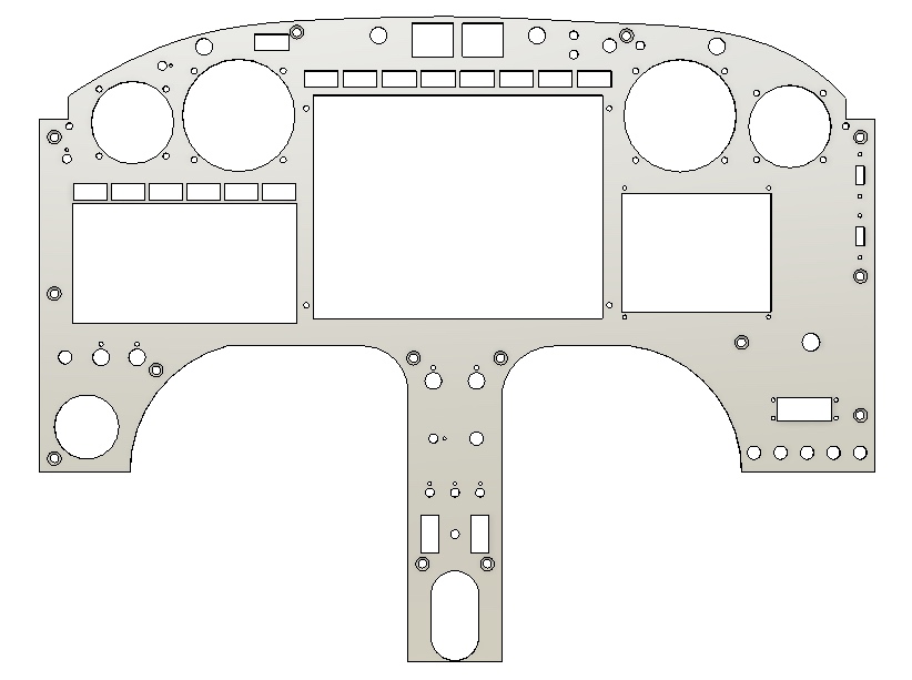
While Subpanel version 4 was busy in its nearly 7 hour 3D printout, I updated the panel with a ton of minor tweaks.
- Shaved 0.040″ off each side edge so panel won’t cut into sidewall from vibrations.
- Notched the upper right corner at underside of longeron — for cable routing.
- Moved the ALT Static switch to the upper RH corner (not sure if I’ll leave it there).
- Moved RAM air & oil cooler louver adjust rockers to left of fuel pump switch (LLHS).
- Re-situated the 4 top row CAMLOCs for the Aft Nose Cover mounting
- Re-situated the 2 top panel screws.
- Lopped off bottom center strut leaving just a hint of the curve for aligninment.
- Added 2x 1/4″ holes to mount modified diamond RAM ball mount for my iPad Mini (via moving the RAM air and oil cooler rockers from the lower center strut to LHS).
- 1/4″ RAM mount bolts will also serve as panel mount bolts on lower center strut.
- Moved on/off indicator lights dimmer to account for the warning sub-panel width.
- Moved gear/canopy warning LEDs to account for the warning sub-panel width.
- Verified distance between Circuit Breakers and right armrest top.
One last task left to do is to shave about 0.020″ off the upper LH “corner”… something that with all my changes this curve mod will be a bit trickier to accomplish.
I also moved the panel’s Push-to-test button for the on/off indicator lights to mount on the right side of the Warning Annunciator Sub-panel in order to get that small push button off of the panel and out of the way [it’s a pain to mount because it’s so small you have to dig out a bunch of original panel to get it mounted].
This of course resulted in Version 5 of the Warning Annunciation Sub-panel… same as V4 except for the mounting plate I created on the right side for the Push-to-test button.
For my last hurrah of the evening, I took a solid Korry light mockup that Marco had drawn up in Fusion 360 and turned it into a hollow, functioning Korry light case and then 3D printed it (on the left):
This will allow us to print these light cases in case we need one a spare. I’m also working on the lettered front plate process to be able to make a complete light unit to customize as required.
For the right side of the warning sub-panel I split the case (below left) in the interior to allow for two different colored annunciator lights to correspond with the two different states that my single switch will manipulate (B/U ALT & E-BUS PWR).
•••
1 September 2020 — As I was checking over the state of the panel mockup, and doing some impromptu dusting, curiosity got the best of me and I cracked open the panel’s Fusion 360 CAD file. That led to another hour of adding in the latest tweaks to get the panel pretty darn close to its final plasma cutting state. My main focus was reposition the switches on the center strut between the leg holes to then position the mounting holes for the RAM ball mount, the result of my iPad operational positioning testing last week.
•••
14 September 2020 — Today I powered through getting my instrument panel plasma cut (8″ cuts at a time!) before I do some straight line test cuts to obtain some troubleshooting data for Langmuir Systems.
Well, my evil plan almost worked. Then at just about the last cut the plasma torch crashed into a raised part of the panel and went all askew. Being the good soldier it kept going to complete its mission, but at that point was starting in the wrong position. It made a nice little “accent” line across the top, and then just about lopped off all my Korey lights in the row above the EFIS.
Luckily this is a test panel, and it didn’t do enough damage to render it unusable.
I added some uber Gorilla duct tape to the Korey light top cross piece and proceeded to test fit the panel into the plane. VERY NOT BAD! A few round of final tweaks to be sure, but very close… I’m very pleased with the outcome.
The fillets along the composite panel edges and especially the corners are keeping it from lying flat on the original composite panel… and being able to be skewed slightly left and a little up. Again, some corner trimming will help immensely on tweaking the final fit.
•••
24 September 2020 — The biggest news of the day is that I finally got my plasma cutter operational again. It took a fair bit of machinations to make it happen, but it is cutting at a very acceptable level now.
So much so that after the initial test cut was successful, I dove right into cutting test instrument panel #2. Here’s the video of the panel being cut.
With the new test panel on hand, I then finished an ongoing series of videos that originally covered both the panel and the canopy latch handle, but the resulting video would have been way too long to stuff into one video, so I broke them up.
Here’s the video on the instrument panel, including the one I just plasma cut:
•••
29 September 2020 — Today I got a good cut on the plasma cutting table of test instrument panel #3. I really do believe this will be the last test panel I cut (although I still need to test fit and assess).
Besides some more shaving off of the upper left corner, the biggest change on this panel version is that I moved the ELT remote control head from just above the row of circuit breakers in the lower right corner, up about 6″ to sit adjacent to the Mini-X EFIS.
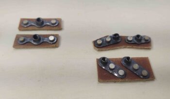
[Interesting tidbit: There are 4 small pieces that were cut out from the panel that are “welded” to the tops of the slats . . . can you find them?]
•••
30 September 2020 — I added duct tape to the back of test panel #3 and then temp installed it for yet another panel test fit. I already see a couple minor tweak points (not worthy of a whole new test panel cut btw) but still need to sit in the cockpit to assess fit before going final with the real 0.090″ thick 6061 instrument panel cutting.
•••
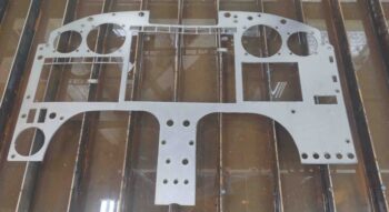
4 October 2020 — Today I plasma cut the REAL 6061 aluminum instrument panel!
I spent quite a bit of time in Fusion 360 CAD today. I got a bit of a late start, and it was quite the dark rainy day. So I had a cup of coffee (or two) and knocked out the CAD updates for the both the instrument panel and the a new, shorter nose hatch hinge.
I then plasma cut the instrument panel out of a sheet of 0.090″ thick 6061 aluminum, as I documented in this video:
Here’s how it looked after I cleaned it up a bit. It definitely wasn’t the best plasma cutting session I’ve had, but there were no major tragedies or damage, so this dog will hunt!
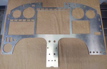
I then test-fit the freshly cut panel in the cockpit, over the stock composite panel (which will serve as a backing/reinforcement panel structure). Not surprisingly, as one would hope, it fits the best by far of all the panel variants.
•••
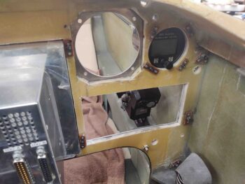
5 October 2020 — I did spend a couple of hours today “playing” around with the panel and looking around to locate some electrical components. I started off by installing the vertical compass card which fit fine, as did the screws in the holes.
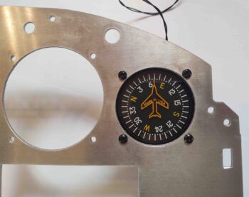
Apparently the cutting action of the plasma creates a beveled kerf on the bottom half of the round cutouts, since every hole required some cleanup almost completely just on the bottom half. After about 10 minutes of filing, the holes were good to go to mount the top instruments into (from left: MGL clock/timer, Trio autopilot, TruTrak ADI, and vertical card compass).
Moreover, of the 16 mounting holes that were plasma cut, only one requires drilling to provide about 0.020″ extra clearance for the screw.
The holes in the center strut were NOT as impressive as up top. For some reason these lower holes were all cut about 0.050″ to 0.100″ to the left of where they should be. I drilled the top (light switches), second (RAM mount) and fourth (component ON/OFF switches) row holes, essentially making them oval vs round.
•••
6 October 2020 — A major pitfall of a long airplane build is simply keeping track of all the massive amounts of data swirling around for each step of the build. It’s easy to say that we’ll verify each and every piece of information, but the truth of the matter is stuff falls through the cracks…. or I should quantify all this with the statement that it definitely does so for me at times.
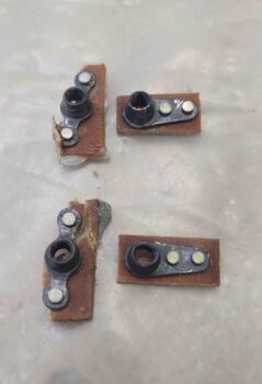
Thus, my assumptions that past Wade had done right by present Wade may have been a bit optimistic in the case of the pair of rocker switches on my panel. I had a rocker switch already targeted for my RAM air open/close switch, but a wiring configuration change quite a while ago ended up making that one obsolete.
Moreover, its twin was to be used to control the oil cooler louver actuator to allow for oil temp to be controlled remotely (and accurately via the EFIS display) from the pilot’s seat. Well that design never came to full fruition, so rocker switch number 2 was also dead in the water before it ever made it to the panel.
Well, it was then probably serendipitous that if any part of the panel plasma cutout was to be kluged, it would be these rocker switch cutouts… because after a good hour+ of research I was able to find a pair of rocker switches that met the wiring & operational use requirements, while only being just a scant tad off from the original panel hole size for mounting. So I pulled the trigger on those . . .
•••
7 October 2020 — I actually did a fair amount of work on the instrument panel today, a bit here and a bit there… but about an hour-and-a-half total. I had to increase the height and width of the GRT HXr EFIS opening a bit in both directions, and also work to square it up some too.
This plasma cut was an odd one since the HXr opening was one of the first cuts out of the gate, and it was a bit off as well. Not horrible, but the row of Korey indicator lights above the HXr is definitely off in relation to the EFIS, and will need a good 2-3 hours to dial in. Moreover, with these indicator lights I’ll now be relying more on the composite sub-panel structure to secure them vs this overlying metal panel.
•••
13 October 2020 — Today I just felt like knocking some stuff out to get the panel as far along as possible today.
I re-drilled the lower left hole on the center strut for the small toggle switch, leaving only the 2 dimmer switch posts left on the strut to be checked and most likely re-drilled as well. I then drilled out the holes in the upper right area for the 2 LEDs that make up the JBWilco gear & canopy panel indicators, and also the hole for the dimmer switch that controls the row of ON/OFF notification lights above the HXr EFIS.
Speaking of the row of ON/OFF indicator (“Korey”) lights, I finished dialing those in to allow mounting the entire row above the HXr EFIS. I also trimmed the hole for the N-number N916WP Korey light in the upper LH corner, while finally getting the 2 outboard Korey annunciators for the GNS-480 completed as well.
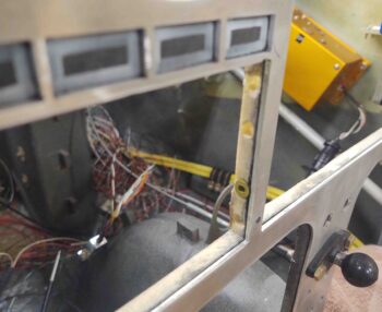
In the lower left corner I set the 2 rocker switches in place just to the left of the red switch-covered fuel pump switch (holes will need welded backfill on edges). These rockers are for the engine intake RAM air valve and the oil cooler louver actuator to control/keep oil temp in the proper range. I also cleaned up the hole for the eyeball air vent which will actually be mounted to the composite sub-panel and just peaking through this aluminum panel overlay. In the same way, the panel-mounted USB ports for each EFIS in the upper right corner (which I verified clearances are good) and the ELT remote control head (mid RHS) will all be mounted to the composite sub-panel vs this aluminum panel overlay, staying with the original any time I remove the aluminum panel.
As I’ve noted a couple times since I’ve been back on the build, working a long extended project has is moments of scrambling to figure out either what past decisions were made, and/or a lot of times why! Well, today I had to put on my Private Investigator’s hat and jump on the case of the missing panel ON/OFF indicator (Korey) lights’ Push-To-Test switch, which has traditionally –on my panel– been right next to the same lights’ dimmer switch.
Hmmm? Where’d it go?
I went back to my couple-versions-old panel CAD drawing and there it was, next to the dimmer switch. My latest panel version? Not there.
Yep, as I started thinking about it I remembered that with the new Warning Annunciator Sub-panel being plopped into the top center of the panel, I had to move some of the components in that immediate area to the side. In short, the panel was getting a bit crowded there. I pulled up the CAD drawing of the latest Warning Annunciation panel, that I was thinking I already had in my hot mitts, and there it was: a mounting hole on the right side for the panel ON/OFF indicator lights Push-to-Test button.
I finished tweaking the drawing since I needed to get the top front of the sub-panel up a bit higher to close the gap it had with the bottom of the glare shield. To do this, I merely added more meat to the bottom flange of the sub-panel and angled the mounting base line (back wall) to tilt the panel up into position by providing a designed wedge under the bottom edge.
I then 3D printed the new Warning Annunciator Sub-panel, which took about 14 hours (I started this print job actually a couple hours before starting on the interior canopy paint clear coat).
With the mounting back (technically forward side) now angled, but still printing the rest of the component vertically, it created a filled in wedge-shaped support raft immediately under all but the lowest/thickest lip of the back (against panel) wall (3D printed face up as in above pic). Well, this didn’t provide the most secure attachment to the printer heat bed and some lifting on the lower attach corners occurred. Nothing that can’t be dealt with or salvaged, but some judicious sanding will need to occur.
Regardless, here’s the missing Push-to-Test mounting hole! Again, on the right side of the Warning Annunciator Sub-panel.
Unless the lifted-corner base is an insurmountable issue, I plan on this being the final version of the Warning Annunciator sub-panel.
•••
17 October 2020 — A worthy point of note on the instrument panel is my command decision to move the planned location of the Master switch, Ignition #1 (ElectroAir) and Ignition #2 (P-Mag) from a plate that would have been just forward of the control stick, onto the lower right corner of the panel. After thinking about it for a few days, I just decided that a switch plate forward of the control stick on the side console would just be too much hassle. The more I thought about it the more I liked the idea of having these switches on the panel: they seem to flow better and the fit is more natural.
A number of hours later, after working on a bunch of other panel tasks, I finally got around to marking up the panel in ‘ol skool fashion for the Master and ignition switches.
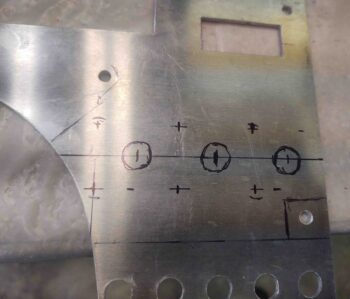
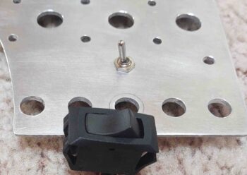
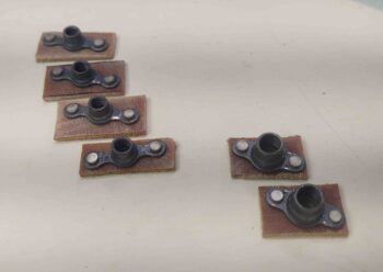
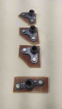
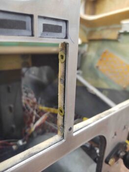
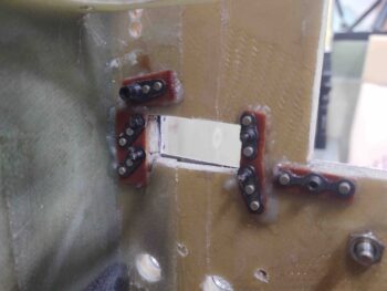
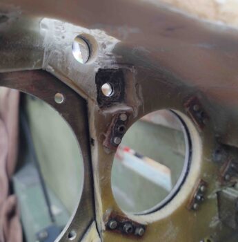
After drilling the master and ignition switch holes, I then used my 3D printed large switch template for drilling keyways on the back side of the panel. I actually drilled the keyways for every large switch on my panel (6 total).
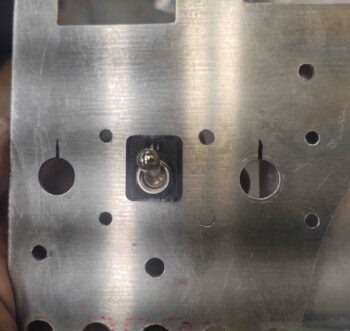
Here I’ve marked the keyway location . . .
And then carefully drilled it out. You want to get deep enough (around ~1/16″) so that the keyway will sit flat on the panel with the key in the hole, but obviously NOT drill all the way through the panel and have a nice hole where you don’t need one.
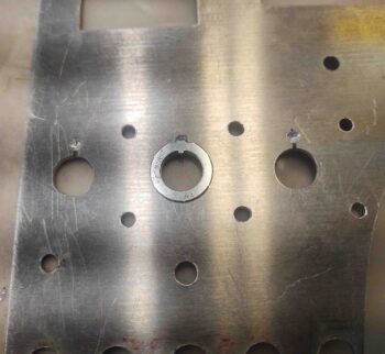
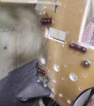
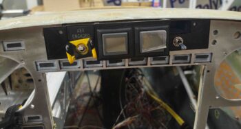
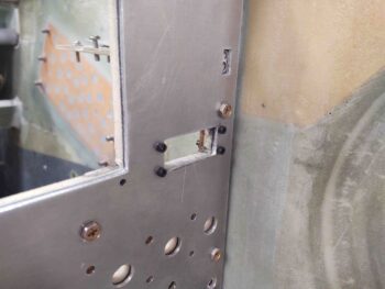
I then reassembled the panel…. this is post welding, so there are a number of areas that I tweaked and repaired by welding the holes in (as in the upper right CAMLOC) or just making them smaller.
Note the 2 holes below the vertical card compass that provide access to the adjustment screws. Also note the 2 dimmer switches on the center strut are installed.
About the only tasks left to do on the panel, besides actually installing it, are fitting the Garmin GNS-480 GPS and drilling the keyways for the small switches.
•••
18 October 2020 — Today I dialed in the GNS-480 GPS so that it fit in the panel and then I drilled the screw mounting holes for the HXr EFIS (#6 screws) and the Mini-X EFIS (#4 screws).
•••
19 October 2020 — I went back to an email my buddy Dave Berenholtz sent me that contained a bunch of good info that he compiled regarding instrument panel labeling. The boiled down info is that there are essentially 4 accepted fonts (and their differing variants) for panels: Helvetica, Futura, Arial and Franklin Gothic… the first 2 used by NASA.
I played around with Helvetica and Futura for a bit, and then tried out what some of the bubbas on the VANs Air Force forum recommended: Arial and Franklin Gothic. The VAF info also recommended 12 pitch font. I noted Franklin Gothic looked better not bolded, but the size seemed smaller than the others so I bumped it up to 13 pitch. I played around a bit more with all of them, but I kept coming back to Franklin Gothic as my label of choice. And also un-bolded at 13 pitch. I printed out a quick sheet and cut up the labels just to check font size. I’m really liking what I’m seeing so I plan on sticking with this one (thanks for the info Dave, very helpful!).
•••
20 October 2020 — I started out today by spending nearly an hour updating a few electrical diagrams and printing an updated consolidated switch diagram.
I also went on the hunt –and found– a toggle switch to replace the rocker switch I had previously identified for the Tach Source Select switch (SW005) –the rocker being a bit too robust to fit on the panel. “Luckily,” I have a lot of spare switches on hand from all my different starts and stops in my journey on my electrical system. I labeled the new switch and pressed it into service.
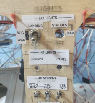
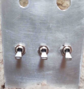
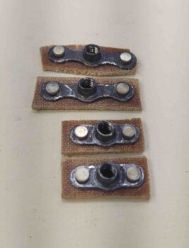
I have 5 mini-toggle switches on my panel, this one being the latest addition. My final prep work on the panel is simply drilling the keyways for these mini-toggles on the back face of the panel.
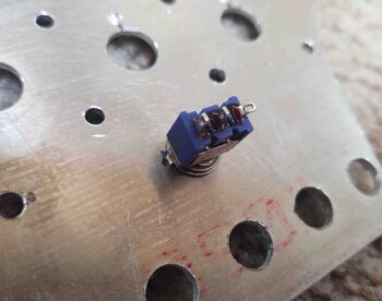
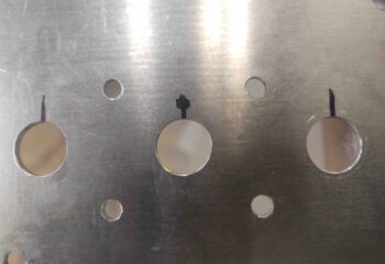
The panel’s big toggle switches, all from B&C, are situated with their keyways on the top. Luckily I decided to tone these switches out with continuity checks to see which direction was ON and OFF, so that I could set the keyways appropriately: these mini-toggles happen to install with the keyways DOWN, opposite their bigger cousins. I also knocked out drilling the holes for the keyways on the 3 AC System switches at the bottom of the center strut.
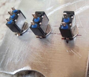
Which look like this on the front side:
I have one more mini-toggle keyway to install for the Autopilot source select switch, but since it’s currently hardwired into the panel mockup, I’m waiting until I tear that apart to drill the keyway.
•••
23 October 2020 — Today I made up a couple 1/4″ (AN4) and four 3/16″ (AN3) nutplate assemblies for mounting the aluminum panel to the existing composite panel structure.
•••
24 October 2020 — I grabbed the instrument panel and climbed inside the plane. I noted all the edges and the center strut alignment with the panel. To be clear, this thing is not perfect nor does it fit like a glove. It will however look great and be completely functional for what I need, and I doubt when it’s installed the gaps on the sides or the slightly offset center strut will barely be noticed.
I started with the big 1/4″ bolts first with the RAM ball mount towards the top of the center strut. Once those were installed and tight, I checked alignments and gaps all the way around again. I then started drilling all the perimeter #10 holes.
Tomorrow I’ll start floxing in the nutplates for these screws/bolts…. which I made up 4 more assemblies tonight.
•••
25 October 2020 — Today I got on to floxing in all the instrument panel securing nutplates: 10 total. The 2 nutplates on the center strut are 1/4″, while all the others are #10.
Here’s the other side. After around 6 hours cure time (fast hardener) I removed each screw, cleaned it, and then re-installed it. I didn’t want to check these floxed-in nutplates tomorrow simply to have a screw permanently floxed into it, although I did apply a thin coat of grease to all the screws before installing.
•••
26 October 2020 — Today I made up 4 each #6 nutplate assemblies for mounting the HXr EFIS to the panel.
•••
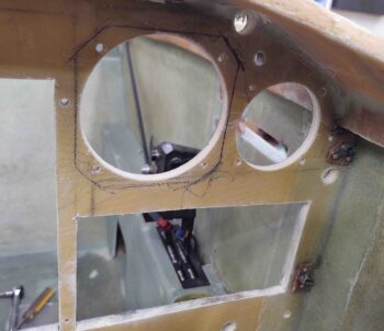
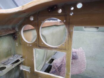
27 October 2020 — I started my panel work by drilling out all the small round holes for switches, CAMLOCs, etc. Since I have 6 aft nose/avionics cover attach points across the top of the panel: 4x CAMLOCs and 2x hinge pin passthrough/threaded attach in the corner by each longeron, I figured I would drill the other panel component holes while I was in drilling mode.
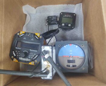
On one of my trips to the house, I stopped and grabbed a box full of goodies.
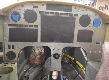
I took a white paint marker and marked the interior perimeter of all the major avionics (and the ELT remote head). Also, before I removed the aluminum panel I ran the Fein saw along the inside edge of the rectangular avionics to score the face of the old panel bulkhead.
I started with the 2-1/4″ hole saw and cut out the hole for the MGL clock/timer. This one is easy because I like this guy mounted with the case on top of the panel. However, it did highlight to me that I need to make 4 more 4-40 nutplate assemblies to mount it.
Of course I also used a 3-1/8″ hole saw to cut the bigger holes for the autopilot and ADI.
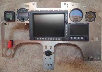
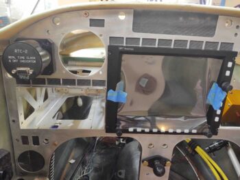
Here I’ve cut the middle row of holes: the GNS-480 GPS, HXr EFIS, and Mini-X EFIS. In addition, you can see I then mounted the Trio Autopilot.
I then marked around the Trio autopilot, essentially using it as a template.
And cut out the mark for the autopilot. I then installed the TruTrak ADI and did the same thing.
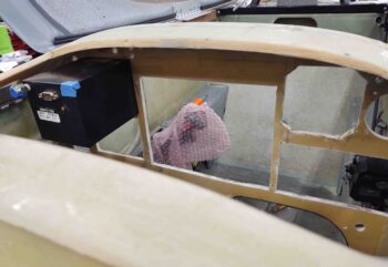
Here you can see I’ve removed the ADI and am ready to cut out the square. Hopefully this is obvious that I’m mounting these instruments straight to the back side of the aluminum panel, so they need to completely pass through the old composite panel bulkhead.
My last instrument to cut the perimeter through the old composite panel bulkhead was the vertical card compass. It sits so close to the ADI that I just cut straight through the right side of the ADI cutout to make a cutout for the compass.
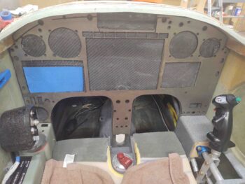
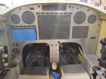
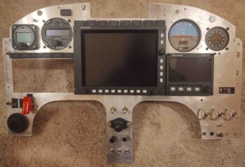
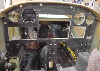
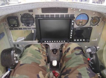
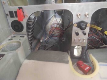
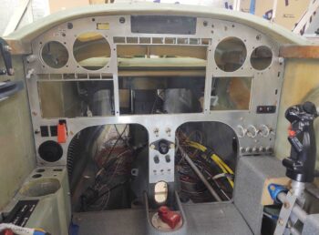
Of course I couldn’t resist climbing into the cockpit and making some airplane noises after I got the panel assembled with a good bit of instruments. I am super happy with how the panel is coming along… I really love the layout and functionality of all the components.
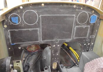
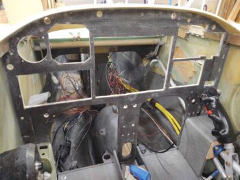
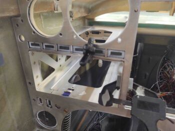
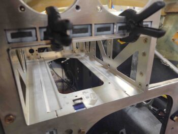
BTW, here’s a shot of the components from behind the panel… note how much access the top open area under the aft nose/avionics cover provides.
•••
28 October 2020 — Today I decided to get some panel components installed.
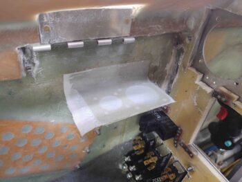
My main goal was the HXr, which I had already made up the 4x #6 nutplate assemblies. Before I started I was going to make up the #4 nutplate assemblies for the Mini-X EFIS, but found as I was drilling out the mounting screw holes (which I overlooked when I drilled all the panel holes) that the top right corner (left in pic) was cracked. There just wasn’t enough meat at the corner so my drilling caused it to snap right through. Not good if I want a 4th screw to secure my Mini-X.
So my plan on floxing in nutplates changed to also laying up a 2-ply patch to that corner (denoted by magenta circle).
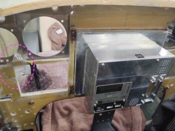
I was actually halfway through making up the #4 nutplates when I remembered I forgot to drill the Mini-X holes (which I discovered last night as I was mounting all the panel components). I then figured I would simply use the #4 nutplates I was working on to mount the MGL clock/timer, which I could do concurrently with the HXr –I couldn’t do that with the Mini-X due to clearance/access issues.
As you can see, I realized I wouldn’t really be able to get to the outboard screws, or at least see them well, so I just flipped the MGL clock/timer around backwards to still get the correct spacing on the screws. Looks odd but worked a treat.
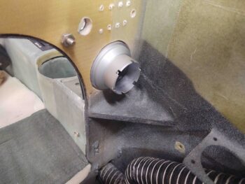
Below is another shot of the HXr EFIS and MGL clock/timer from the front side of the panel. However, the more important item in this pic is the Garmin GNS-480 GPS mounting tube in place. It took just a few minutes sanding down the edge of the composite panel bulkhead to get it to fit, but it does fit… and well!
A point of note: what didn’t take “just a few minutes,” but rather over half an hour, was simply removing all the wiring connectors off the back of the GNS-480 mounting tube… what a hassle! Crazy difficult job for what should seem like an EZ little one.
Moreover, speaking of seemingly EZ jobs: between making up the #4 nutplates and sanding down the edges of the #6 nutplates to fit close enough to the HXr EFIS, this entire endeavor took over 2-1/2 hours to complete!
One area I’m extremely pleased with is the fit of the GNS-480 mounting tube. The back outboard corner (upper right in pic below) is a good 0.150″ off the side wall, which means I was able to drive the GPS unit far over to the left, very close to the sidewall and still obtain good clearance on the side.
Today and tonight really was another heavy planning and coordination work day. I don’t have any pics, but I was going to mount my ELT remote head under the aluminum panel and embedded into the composite panel, until I gathered it up to test the spacing. Then, upon looking at it I remembered it has a battery that will need replacing every so often. Even if it’s every 5 years I don’t want to have to remove the entire panel just to change a battery –not worth it– so I decided to mount it externally on the face of the aluminum panel. This means, yep, another four 4-40 nutplates on the list!
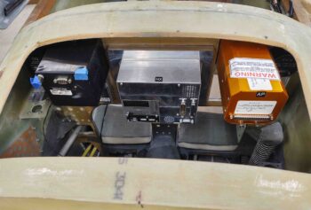
I also assessed spacing for my WxWorx XM satellite radio weather receiver, and am happy to report it appears that it will fit just fine top centerline just forward of the panel.
•••
29 October 2020 — I got busy making up 4x 4-40 phenolic nutplate assemblies for mounting the GRT Mini-X EFIS. After some prep work I then floxed the 4 nutplate assemblies into place.
A bit later as I was poking around the aft side the panel figuring stuff out (still…) I noted that I will need to replace the 2 lower perimeter nutplate assemblies on the right side of the panel due to clearance issues (with remote EFIS USB and P-Mag ignition switch). I added a magenta arrow in the lower left corner of the pic to show the lowest of the offending nutplates.
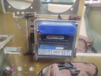
Here we have the bottom two 4-40 nutplate assemblies floxed in place that will secure the Mini-X to the panel.
In addition, I included a green arrow on the left side of the pic to show the second oftending nutplate that must be extricated and replaced.
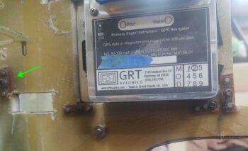
Here’s a shot of the front side of the Mini-X as it serves as a screw placement template for the 4x 4-40 nutplates floxed in place.
Just over the top of the Mini-X you can see I added a blue arrow pointing at an electrical connector bracket… ah yes, this must be relocated a bit higher and slightly forward as well for everything to fit. Yep, we’re definitely getting to the nitty-gritty details stage of the game where apparently everything has to fit… ha! (Also note that I installed the autopilot pitch servo to ensure the spacing is good when I move that bracket).
Once I got the Mini-X squared away and the nutplate flox curing, and checked a few configuration/spacing items (as noted above), I drilled and prepped 4 holes on the outboard edge of the composite bulkhead panel opening for the GNS-480 GPS mounting tube. I then prepped and carefully floxed in 4 RivNuts to match the mounting holes on the outboard side of the GNS-480 mounting tube.
I also drilled and prepped the 4 opposite/inboard side mounting tube screw holes as well. I was only planning on floxing in the 4 outboard RivNuts to start, but since I had enough flox left over for one more RivNut I quickly prepped another one and mounted it on the inboard side.
I waited a couple of hours for the flox to “green” so that it was firm and sticky, but had enough body to let me secure the screws in place. If I had any slight alignment issues, the not yet cured flox would give a little to conform to the screw pattern.
Also, to ensure the weight of the GNS-480 mounting tube didn’t pivot front end down, I clamped it in place.
•••
30 October 2020 — I oftentimes like to do an added extra task that’s off script and not on the day’s task list. Well, today I was curious if I had a 2″ hole saw that I would need to install the panel mounted eyeball air vent. Rootin’ around in the garage I found my old hole saw kit and it had a 2″ diameter bit.
I decided it probably wouldn’t take that long, so curiosity got the better of me and I fairly quickly drilled out the hole(s) for the eyeball vent.
A couple things on this configuration. First, I don’t actually have the vent mounted on the aluminum panel face. If I remove the aluminum panel, it simply slides off around the eyeball vent. This leads to point #2: the exterior diameter of the vent is 2″ (actually closer to 2.1″). However, the mounting diameter on the interior (silver colored) and exterior (black) pieces is 1-3/4″.
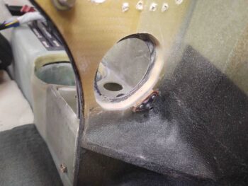
To do this, I started with the 2″ hole saw from the back of the panel (nose) and drilled towards the face of the panel (tail). I carefully closed in on the glass on the front face of the composite panel bulkhead and then stopped just short of it. Then I drilled from the face of the panel toward the backside (again, nose) using the 1-3/4″ hole saw.
I needed to make the ~2″ side just a bit wider in diameter so I used my Dremel Tool with a sanding drum for no more than a minute. It probably took longer to vacuum the mess up then it did drilling and Dremeling it all.
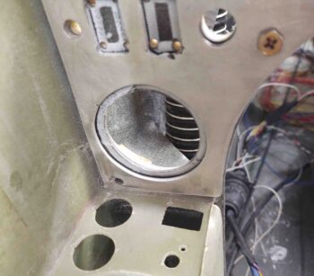
And here’s the mounted eyeball vent. Remember, the panel will be black as well so the seam around the edge won’t be hardly noticeable.
Here’s the back view ….
I then removed the 2 offending perimeter nutplates on the right side of the panel. I got busy making up 2 more nutplate assemblies to replace the ones I just ripped out… which took a fair bit of pounding (boy, this flox stuff really works eh?!)
I then floxed the new nutplate assemblies into place.
I had also prepped the 3 new RivNuts for the inboard/right side that will secure the GNS-480 mounting tube. Since their strip of panel on this side is narrower than the RivNuts are deep, I decided that on 2 of them I would keep the top flange and trim off some of the back side (where more threads are), while on the other 2 I would cut the top side off and gain about 1/8″ more thread.
As I did on the outboard side yesterday, I waited a couple of hours until the flox “greened” and then installed the GNS-480 mounting tube and secured it in place with the screws. BTW, once the flox fully cures this officially finalizes the install of all my major panel instruments.
Before I closed off access behind the panel for a while by glassing the aft nose/avionics cover hinge tabs, I mounted the top 2 screws that secure the warning annunciation sub-panel to the top center of the panel.
Here are the 2x #6 nutplates for the warning annunciator sub-panel top screws. I need these in place to assess spacing for the aft nose/avionics cover tabs that will sit outboard of these nutplates and be secured by CAMLOCs. You can see the panel CAMLOC holes on each edge of the pic.
I then made up another pair of #6 nutplate assemblies for the warning annunciator sub-panel lower screw holes (L – I mounted these later in the evening, but failed to get a pic of them in place). I also made up a couple of double 4-40 nutplates for mounting the ELT remote head (R). This round of nutplate assemblies pretty much does it for the panel, at least at this point.
•••
31 October 2020 — I got a call this morning that Marco would be flying down for a visit this afternoon. While he was getting airborne I ran out to the shop and threw all the avionics and instruments into the panel, including the GNS-480 GPS.

Later on . . .
Since the heavy lifting was complete with the install of the main avionics, I mentally broke down the sections to be completed: the lower left corner, followed by the center strut, the lower right corner, the mid-section, the upper section, and then all the Korey lights: GNS-480 annunciators and panel ON/OFF indicators.
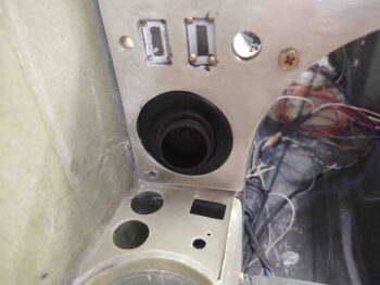
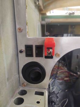
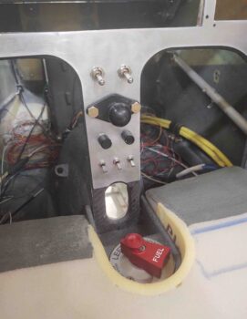
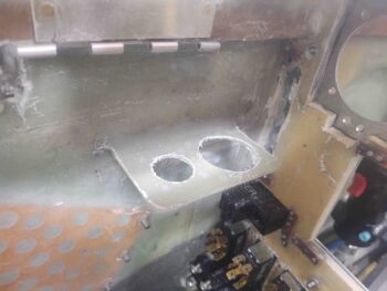
So today was the first to be completed of all those sections: the lower left corner. Here we have the eyeball air vent installed, the outboard oil cooler switches installed, the RAM air open/closed rocker switch installed, and the red flip covered fuel pump switch installed. To be clear, installing these switches meant clearing out a good bit of material on the back (nose) side of the original composite panel bulkhead.
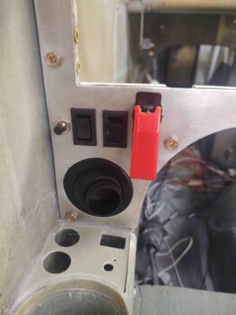
Another shot of the fuel pump switch in the ON position.
My last task of the evening was slightly increasing the size of the opening on both the aluminum and composite panels to accommodate the ELT remote head to be mounted externally on the face of aluminum panel. I drilled the four 4-40 holes through both panel structures, and tomorrow I’ll flox in the phenolic nutplate assemblies to secure the screws.
•••
1 November 2020 — I started out first thing in the shop today floxing in the phenolic nutplate assemblies that will secure the ELT remote head to the instrument panel. Since the ELT remote head housing is plastic, and I like to have the nutplates set in flox nice and tight, I removed the ELT remote head so it wouldn’t get damaged.
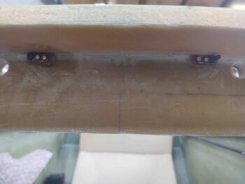
Here are the ELT remote head 4-40 nutplates floxed in place on the back side of the panel.
I then got to work on cutting, drilling and Dremeling out the switch and dimmer mounting positions on the back side of the panel center strut.
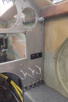
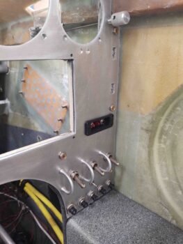
Here’s the result. I’m really pleased with how the components look installed.
 Another shot, including the lower left part of the panel with the switches I installed last night.
•••
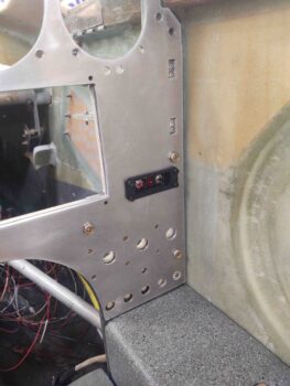
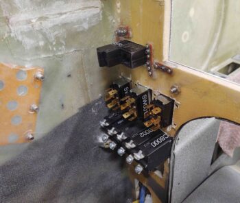
3 November 2020 — Today I spent a good 45 minutes working on the lower right panel. It was getting a bit late, and using the Fein saw makes a LOT of noise, so after I got the circuit breakers and tach source select switch installed I called it a night.
•••
4 November 2020 — Tonight I spent a good hour or so before it got too late to use the very loud Fein saw to finish making the pockets on the back side of the panel (technically forward/nose side. . .) for the big 3 lower right panel switches.
Here’s a shot of the lower right panel after removing material from the original composite panel bulkhead for the switches to fit properly and deep enough.
Note in the upper left corner you can see where i also cut out the sidewall bracket that secured a couple of electrical connectors. That will be moved up slightly and forward a hair.
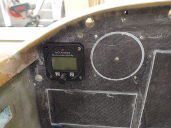
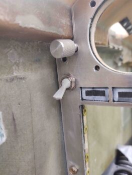
I also cut out material in the original panel to mount the alternate static source switch on the upper left side of the panel.
With the lower left, middle strut, and lower right panel components mounted, I’m now moving into the middle area of the panel, which only has a few components: the aforementioned (complete) alternate static source switch and the 2 EFIS remote USB panel ports on the middle right edge of the panel, just below the longeron.
•••
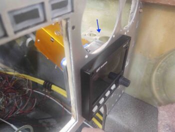
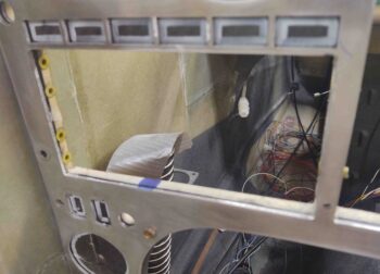
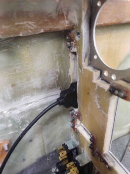
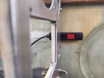
5 November 2020 — I got to work on cutting a notch out of the composite panel bulkhead to accept the HXr and Mini-X EFISs’ remote USB cable ports.
Here’s the top remote USB port for the GRT HXr EFIS.
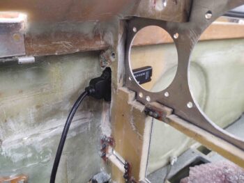
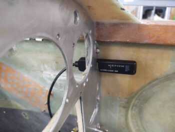
And the bottom remote USB port for the GRT Mini-X EFIS.
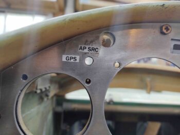
Pressing forward, I measured the autopilot source select switch that’s currently hardwired on my panel mockup and then cut out the appropriate amount of material out of the composite panel bulkhead to mount it in the real panel.
Here’s the shot from the front (I snagged the test label out of curiosity as well).
•••
6 November 2020 — Here’s a shot of all the lower panel components in place.
•••
9 November 2020 — Today I got busy remounting the avionics bay electrical connector bracket on the interior right nose wall. I 5-min glued it in place and then a bit later added a flox fillet and a ply of BID on top. I then peel plied it.
Note: I’m reporting this bracket movement here on the panel page since moving it is specifically related to the panel install.
•••
10 November 2020 — I started off today by pulling the peel ply on the repositioned/re-glassed avionics bay electrical connector bracket. I then cleaned it up a bit and did a very quick razor trim. I still need to add another ply on the bottom, so I’ll do the final cleanup then.
Note: I’m reporting this bracket movement here on the panel page since moving it is specifically related to the panel install.
•••
11 November 2020 — I started off today laying up 1 ply of BID on the underside of the avionics bay electrical connector bracket. I then peel plied the layup.
Note: I’m reporting this bracket movement here on the panel page since moving it is specifically related to the panel install.
•••
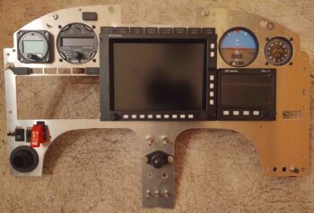
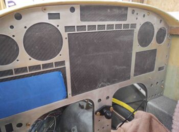
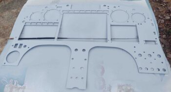
25 November 2020 — I had previously filled a few of the small divots and rough hole edges in the instrument panel with Metal Glaze. And since it was another nice weather day today, after one final good wet sand and acetone wipe down of the panel I took it outside and hit it with a couple of coats of primer.
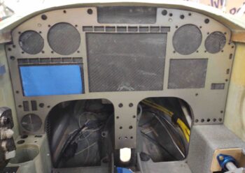
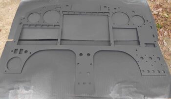
I then shot the instrument panel with 3 coats of SEM black. I know it looks more dark gray in the pic, but in person it looks black. And although I don’t show it here, I then took the panel inside and baked it in the oven for about 1-1/2 hours at 175º F.
•••