
Chapter 8 – Headrest, Rollover, Seat back & Seatbelt Brackets
Step 6 — Installing Seatbelt Brackets
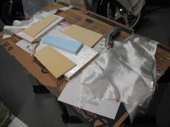
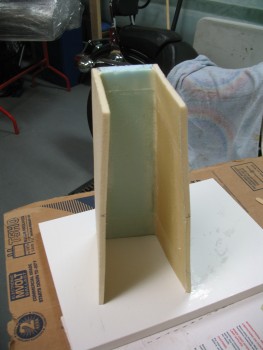
Preamble: Chapter 8 covers two main things: Building the triangular foam & fiberglass headrest that is a hallmark feature of the Long-EZ, and installing the seatbelt brackets. Technically, for my build, two adjunct items come into play in this chapter as well: the pilot’s upper seatbelt brackets get glassed into the base of the triangular rollover assembly, and the plans call for a step to be built and mounted on the left exterior side of the cockpit (that conveniently enough shares the same bolts as the pilot’s left seat belt bracket). I, in holding the line with the vast majority of Long-EZ builders, am NOT installing this step. Also, like many other builders, I am not building the traditional triangular headrest.
Why? Safety.
There’s been an accident or two where that headrest really was only good for being a headrest, and not as a rollover assembly, or “roll bar.” In the future I will build a metal rollover bar that I will install in lieu of the composite one (I have a MIG welder stashed away in storage in Virginia that I will most likely use to construct the roll bar).
Now, back to the main subject of this page, which is seatbelts. As I mentioned in Chapter 7, I am installing my seatbelts out of sequence so that the brackets will be in place BEFORE the final glassing of the fuselage. Why it’s done the other way around—glassing the fuselage first and then installing the seatbelt brackets—I have no idea (other than maybe that’s how it was more easily done when installing the step… which obviously has to mounted after the fuselage is skinned).
Thus, I’m installing the seat belts (Chap 8) before the fuselage gets glassed (Chap 7).
•••
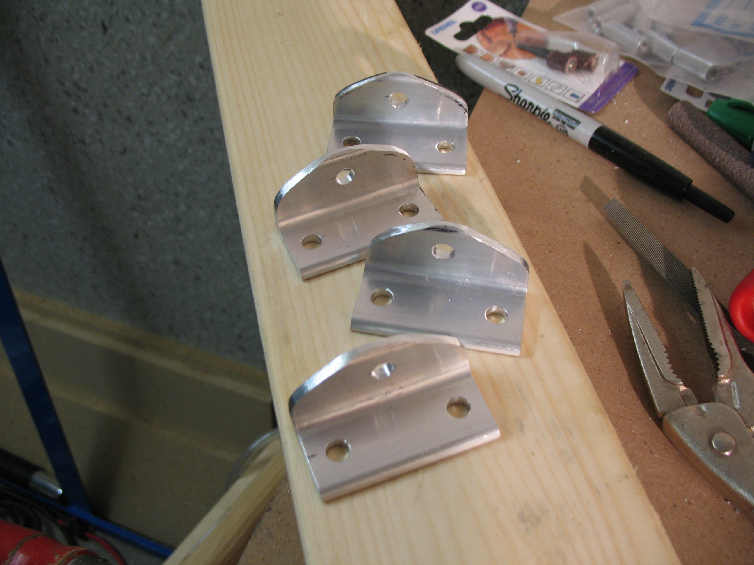
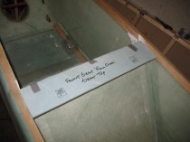
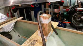
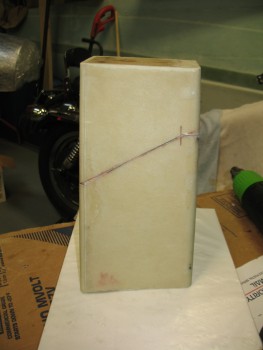
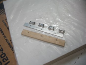
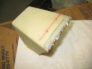
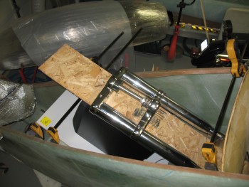
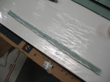
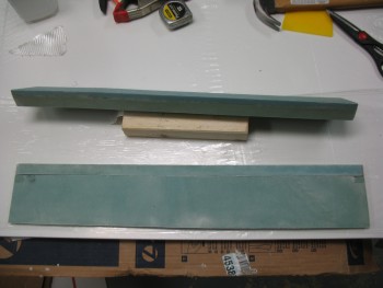
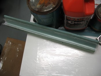
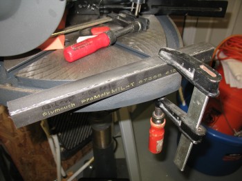
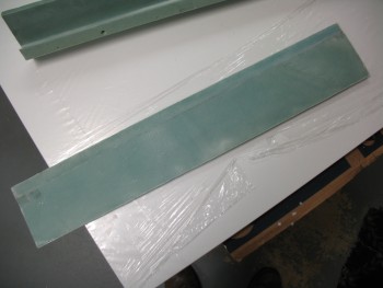
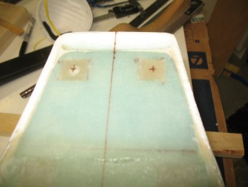
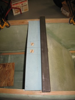
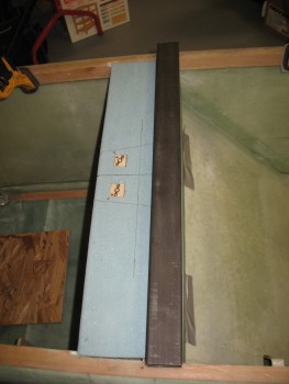
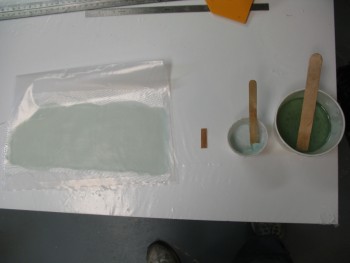
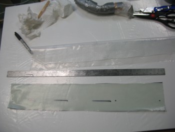
1 June 2012 — Knowing that I was going to be installing the brackets for the seatbelts in the not-too-distant future, I marked up a 1/8″-thick 2024T3 aluminum angle piece for all 4 seatbelt brackets for the interior of the fuselage. I planned to cut those as soon as I got the chance.
•••
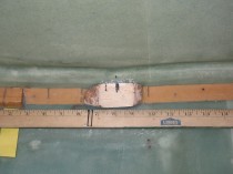
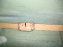
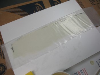
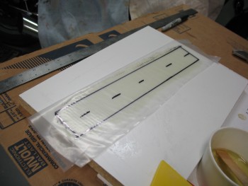
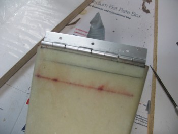
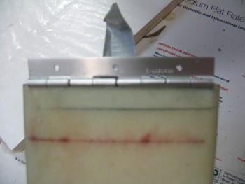
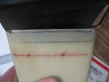
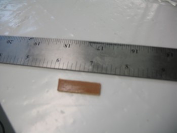
2 June 2012 — I made the initial cuts on the seatbelt aluminum angle extrusion, and also planned and marked the bolt hole positions for the seatbelt/bracket attachments.
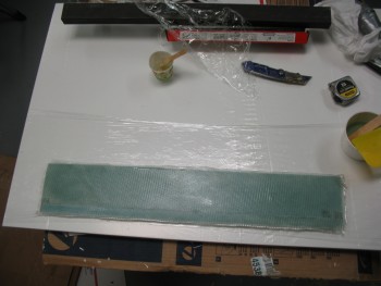
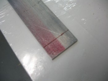
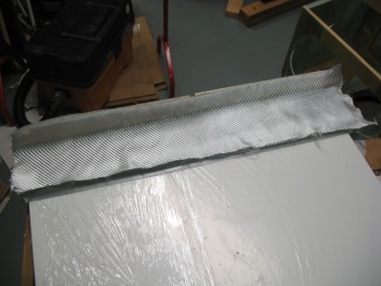
I drilled all the holes in the seatbelt aluminum angle extrusions, and then cut one bracket completely out and filed down the edges. Although not a perfect specimen of machining, it looked pretty good! (Pardon the pic, I know it’s quite blurry)
•••
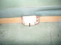
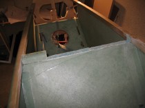
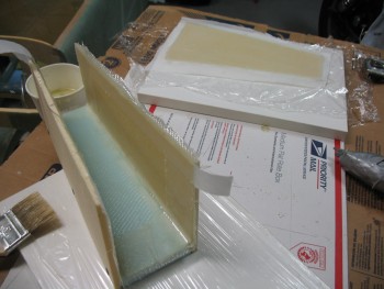
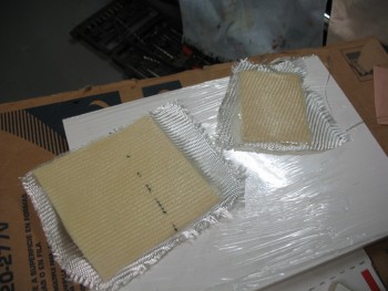
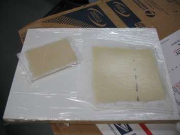
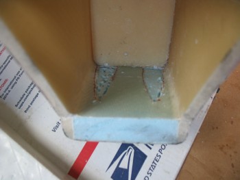
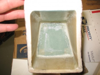
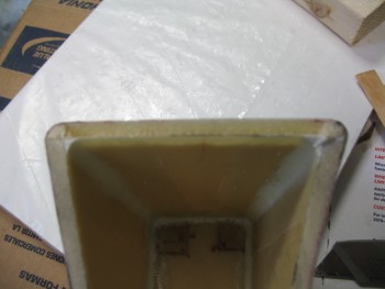
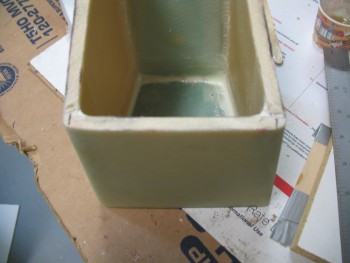
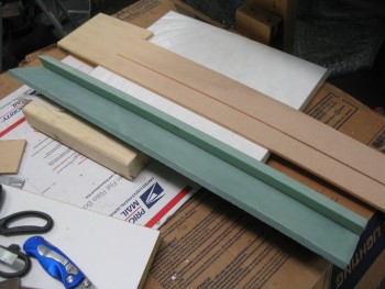
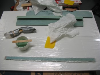
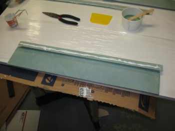
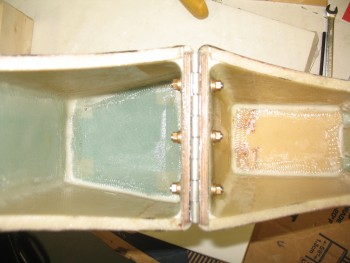
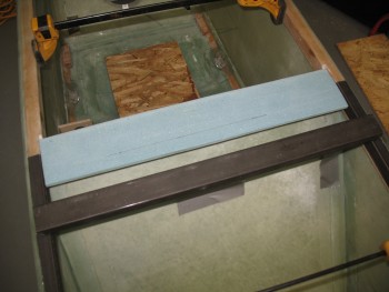
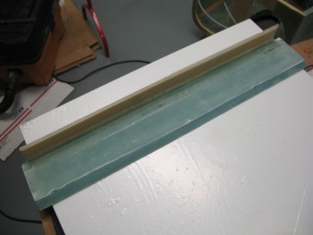
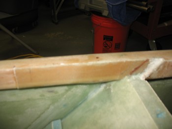
5 June 2012 — Before it got too late at night (that noise ordinance thing again!) I started out the evening by cutting 4 pieces of 1/4″ Finnish Birch plywood for the hard points that will be glassed into each side of the interior fuselage corners where the seatbelt brackets will mount. There is a 7-ply BID layup that goes over these 1/4″ ply hard points, so the seatbelt mounts are designed impressively robust & strong. Since the pads that will be made up of the 7-ply BID aren’t that large, I scrounged together some scrap BID to throw into some “Poor Man’s” pre-preg set-ups. Once I got the set-ups ready, I set them aside to use in the next few days. (Sorry, no pics just yet)
•••
6 June 2012 — My initial discussion on the out-of-sequence seatbelt bracket install:
This mod is a result of one of those head-scratching moments all of us builders have reading the plans. I didn’t understand why we skin the fuselage, and then turn around and drill holes through the skin to mount the seatbelt brackets. I read, looked at the diagrams, reread the plans and it just didn’t seem right to me. I Googled it, and then hit the blogs and the phones. I talked to my building mentor, Dale Martin, and others and still didn’t have a good feel for why the build sequence between the seatbelt bracket mounting and skinning seemed reversed (for the record, Dale suggested I follow the plans).
I finally made a command decision. Not wanting to drill through perfectly good glassed fuselage skin, I decided to mount my seatbelt brackets before I glassed the fuselage. Thus, below you will see exactly that: the start of my seatbelt mounting.
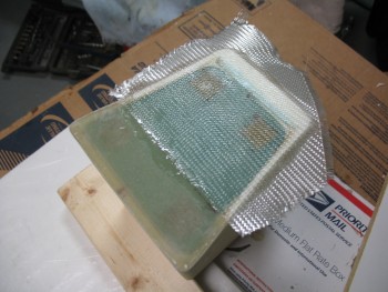
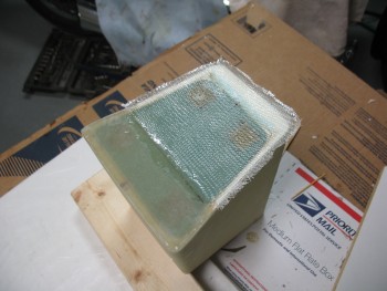
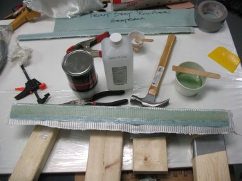
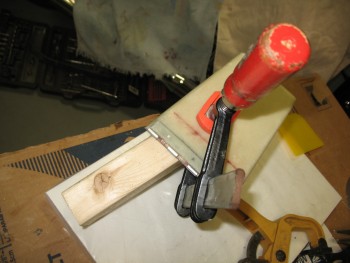
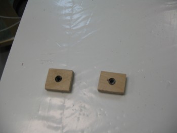
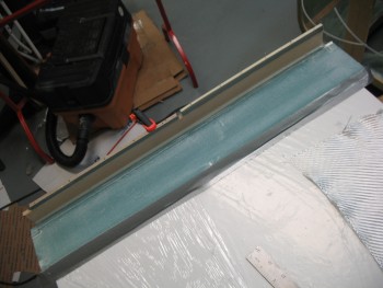
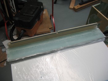
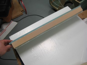
First, I finished cutting & sanding the 1/4″ plywood seatbelt hard points and then mocked them up for install. They looked good so I floxed them in place. I then wetted out the 7-ply BID “Poor Man’s” pre-preg setups that I had made up the night before, and then respectively glassed in the 4 seatbelt hardpoints with 7 plies of BID on each one. I then covered these 7-ply layups with peel ply and overlapped it onto the surrounding glass to get a nice, smooth transition. All the layups looked good, so I left them to cure.
•••
7 June 2012 — Today was a non-building day.
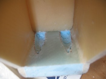
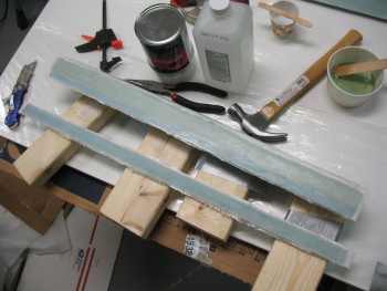
I checked the 7-ply BID layups on the seatbelt bracket hard points and they looked good so I pulled the peel ply off and called it a night.
•••
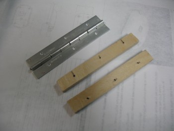
8 June 2012 — I drove down to Aircraft Spruce EU in Bretten,Germany, about an hour and a half from my house, to pick up 28′ of 1/8″ 3003-0 aluminum tubing for my brake lines. I also picked up some Alodine, a 3′ hinge and a plastic eyeball vent.
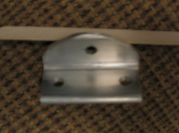
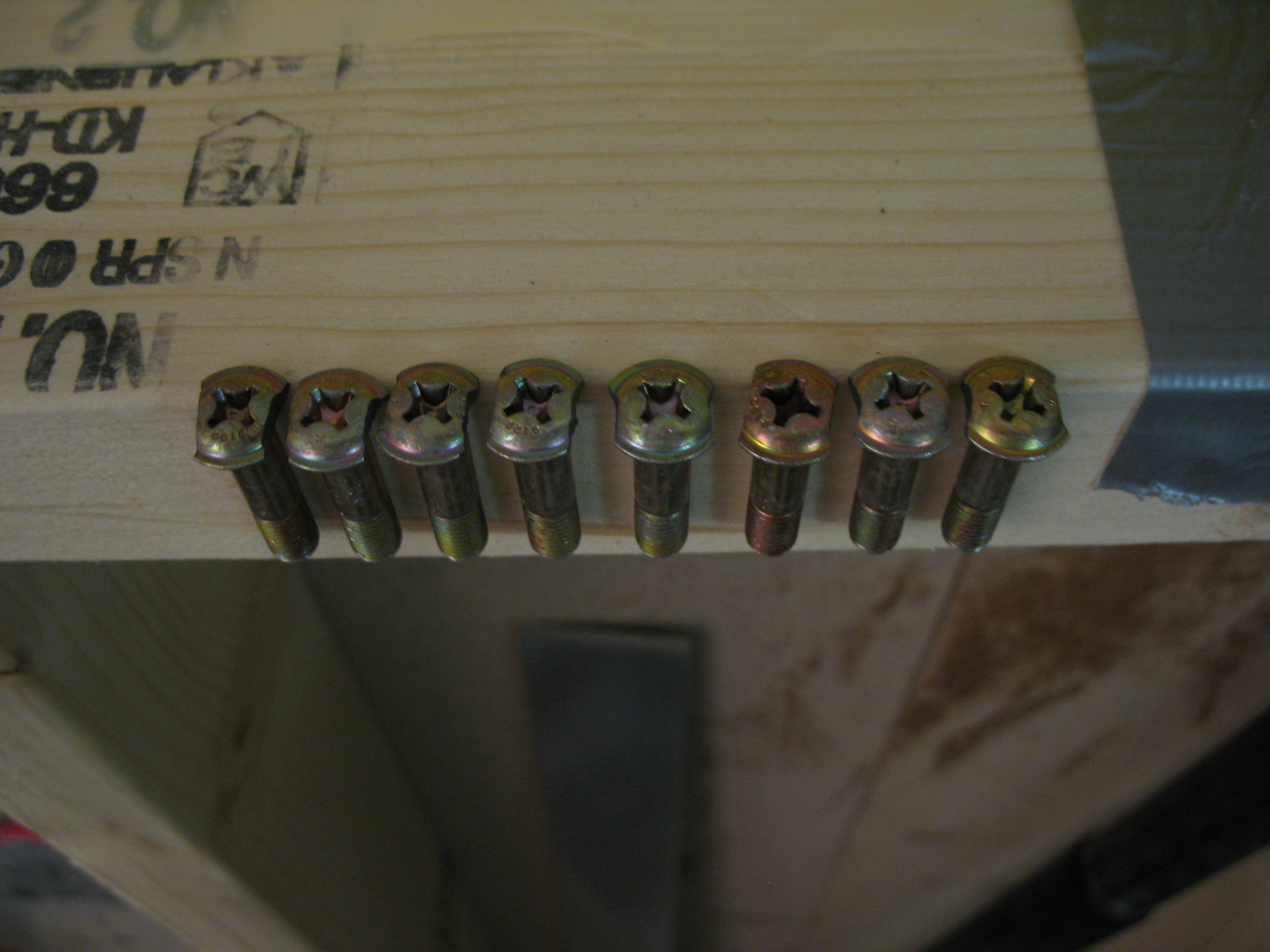
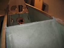
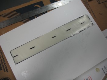
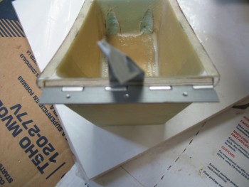
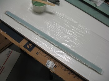
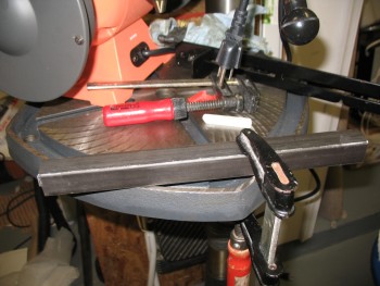
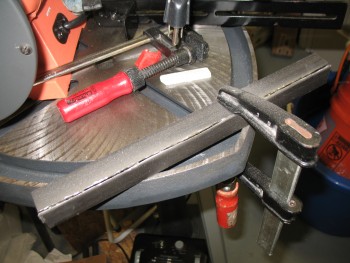
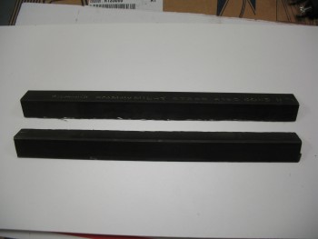
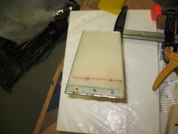
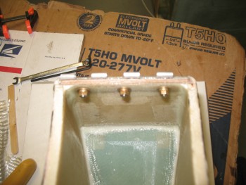
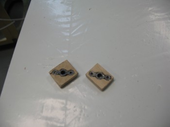
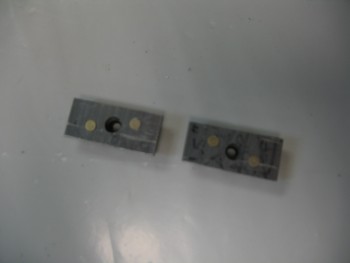
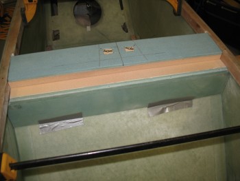
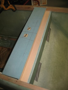
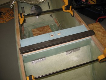
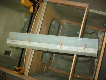
When I returned to the house, I finished the other 3 angled aluminum seatbelt brackets and drilled all the holes to 1/4″.
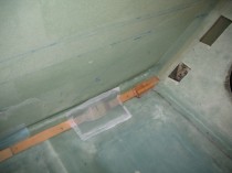
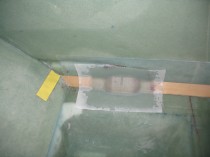
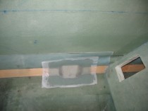
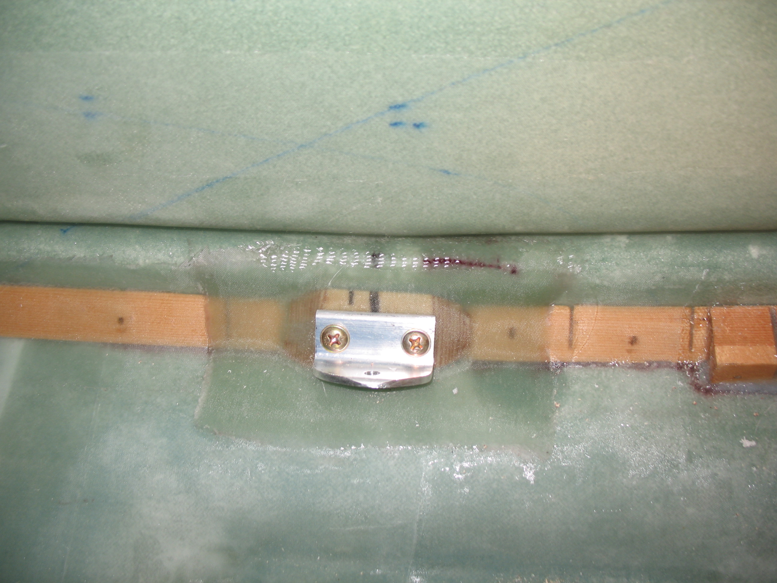
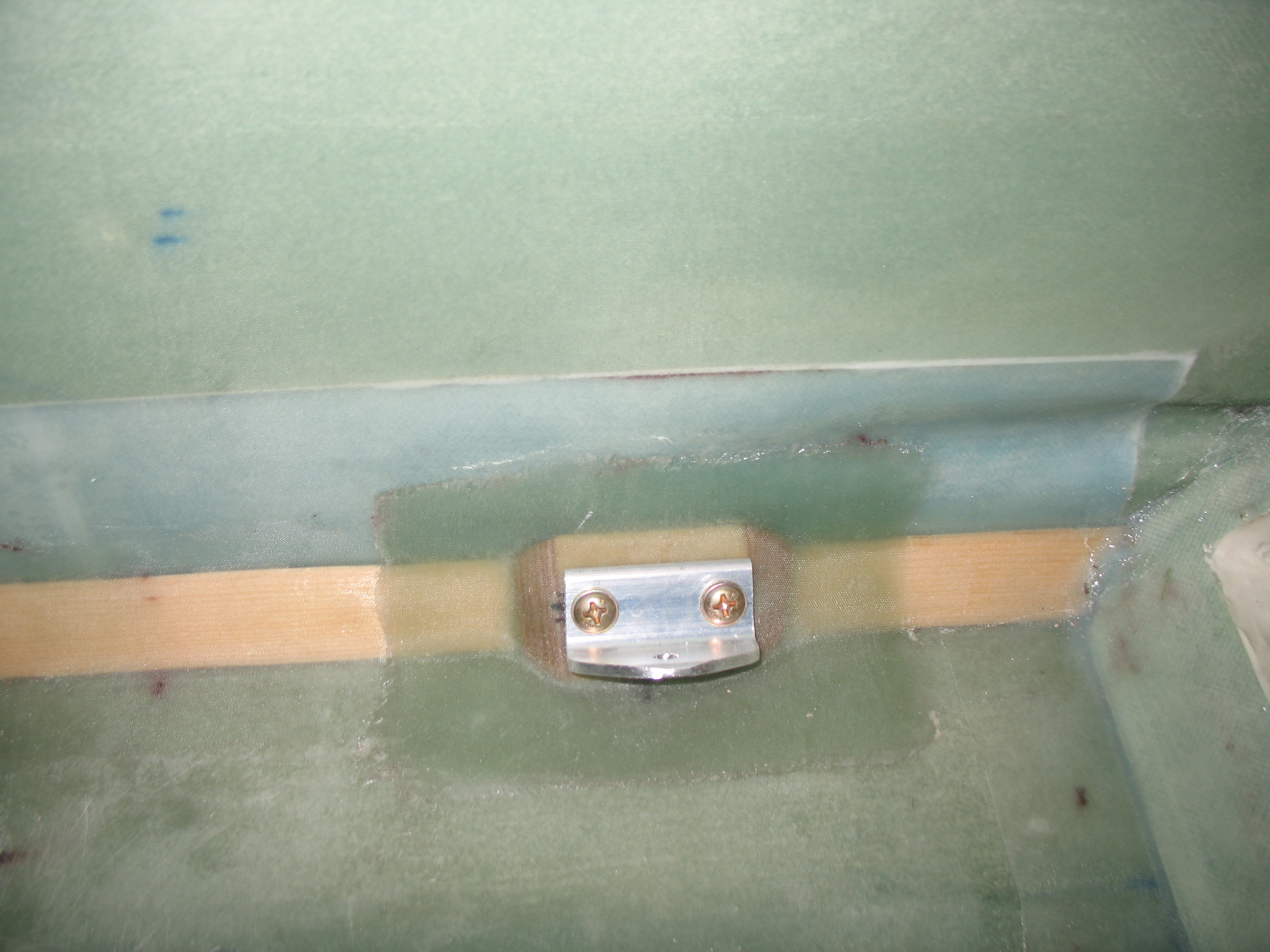
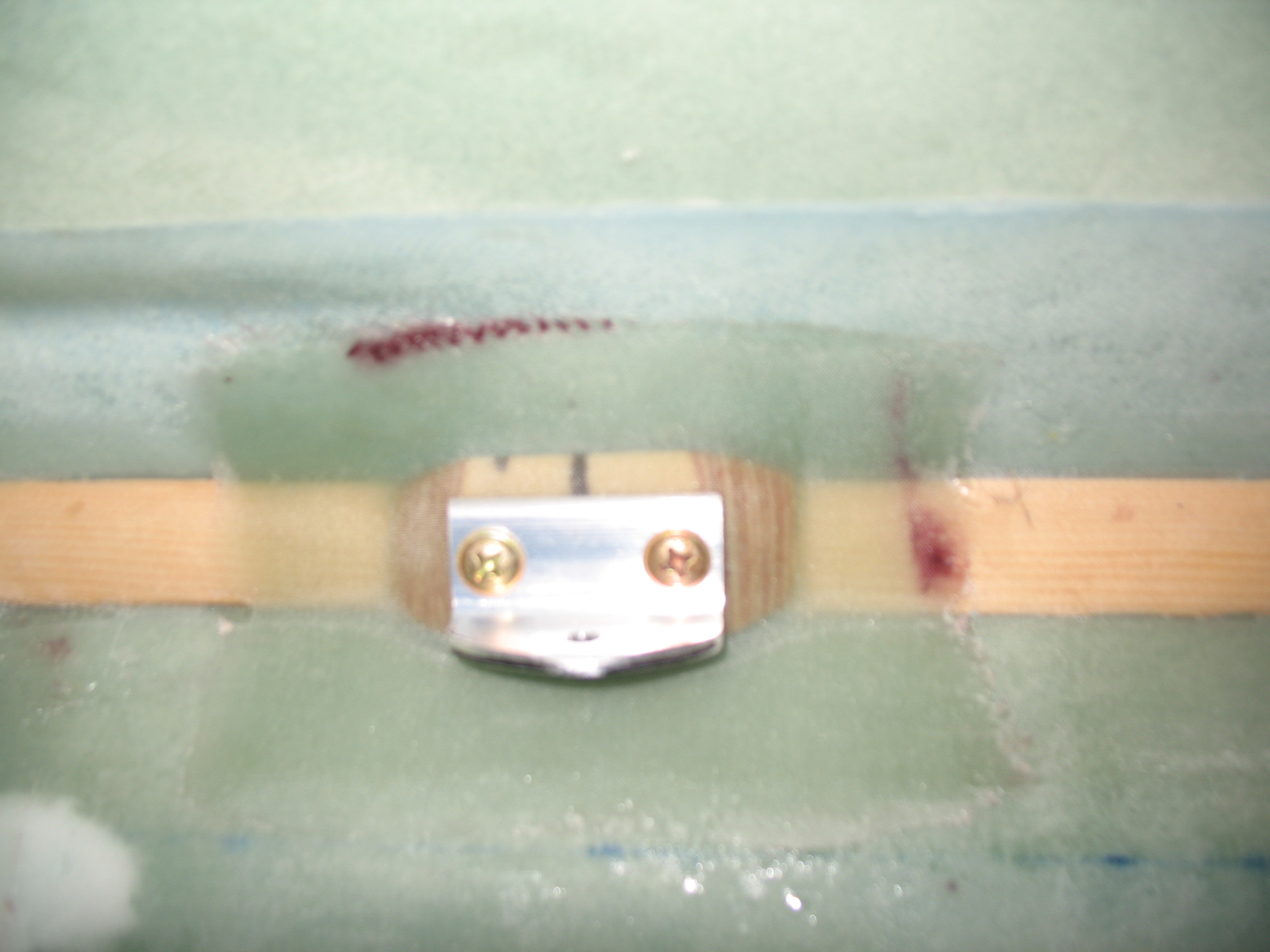
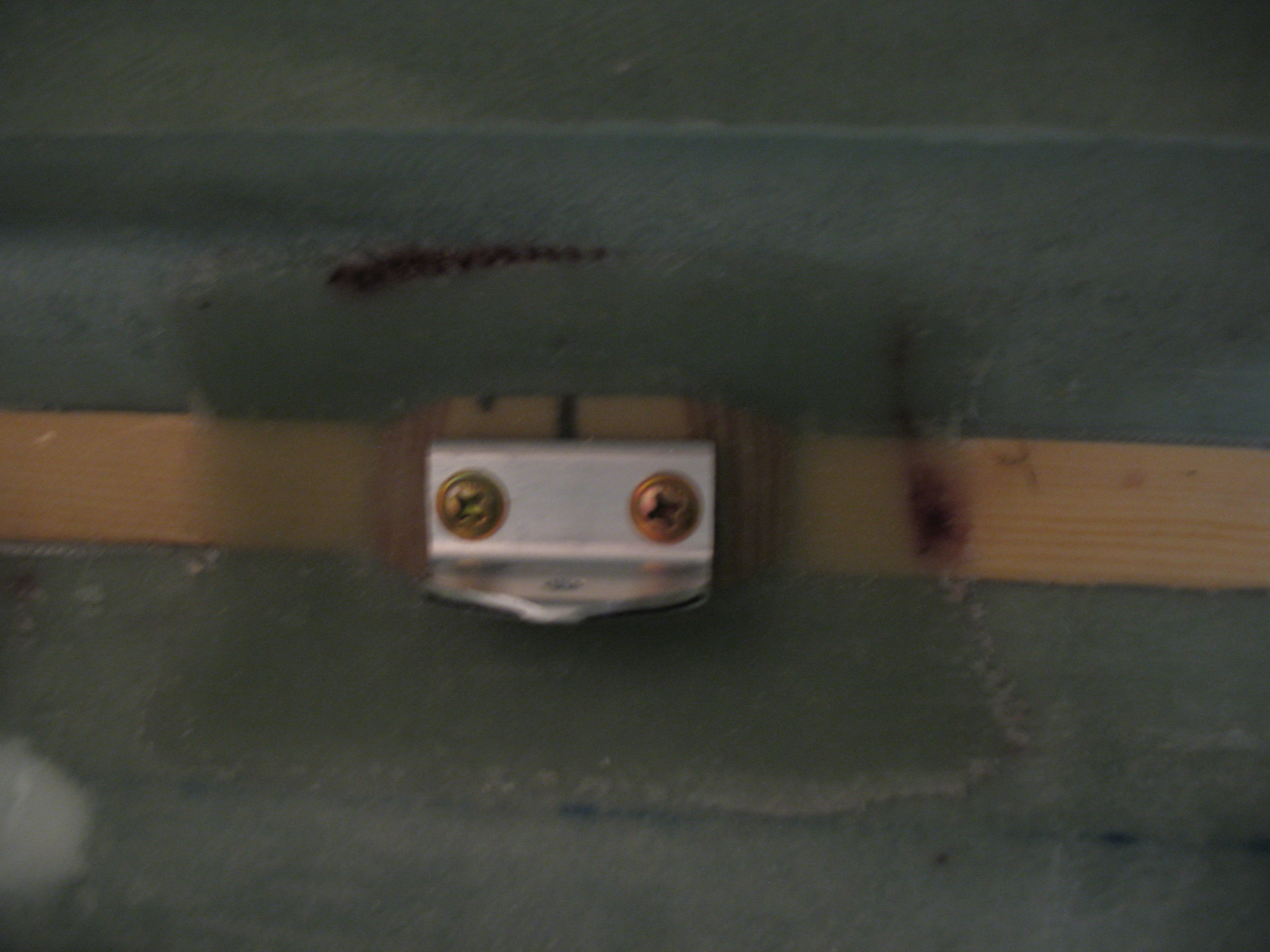
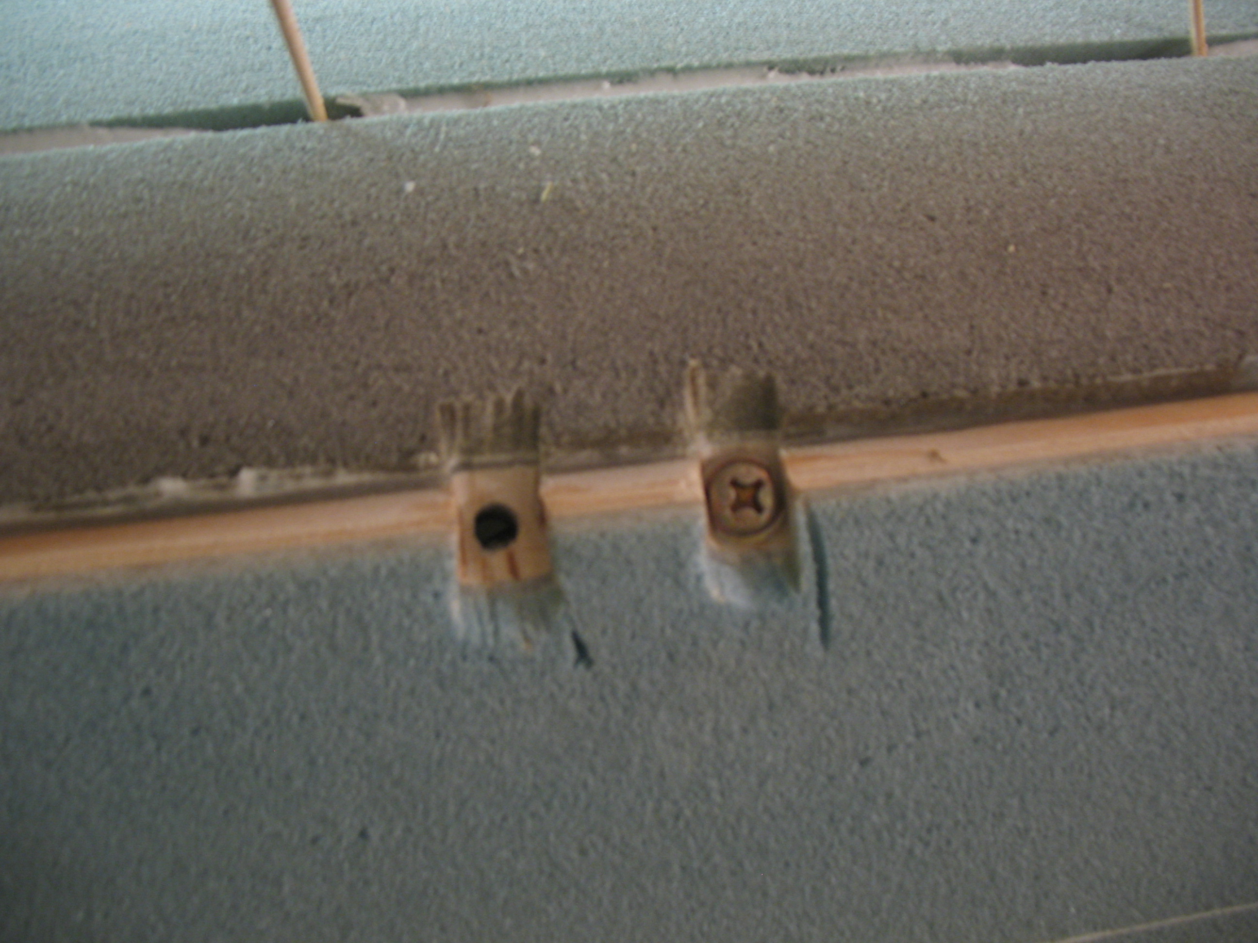
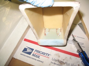
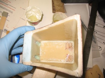
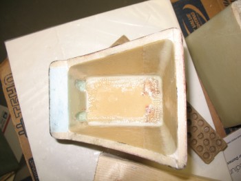
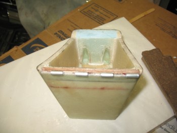
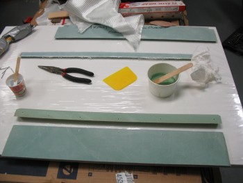
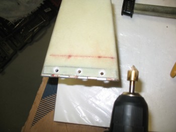
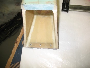
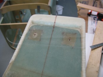
 I then lined up and drilled the seatbelt bracket mounting holes into the corners of the fuselage at each of the 4 seatbelt 7-ply BID/1/4″ plywood hard points. Note that in the pics below that the screws are simply inserted into both the seatbelt bracket and hardpoint holes for spacing purposes only, since the screws are installed backwards—as you can tell by the screw head being on the inside of the fuselage vs. the outside.
•••
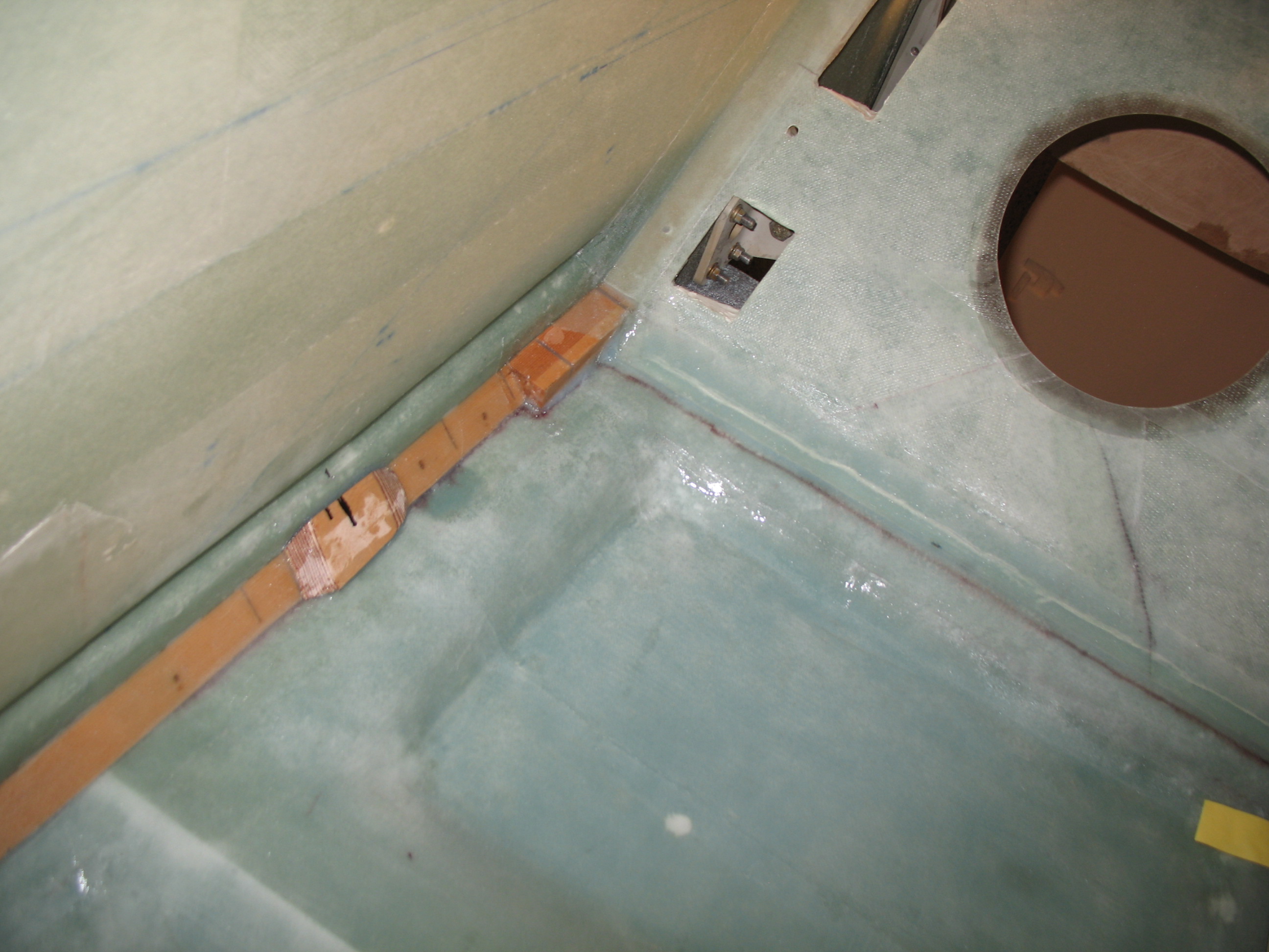
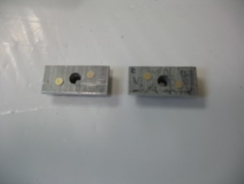
9 June 2012 — In yet another discussion with Dale Martin, he cautioned me that long before the click-bond era, many a imbedded bolt and screw would either vibrate out of the their flox mooring, or simply break loose when either being tightened or during nut removal. So, how do we ensure this doesn’t happen? Well, we make the screw head NOT round and give it an edge… for flox to grip, and provide a physical stop that prevents the screw head from turning. I ended up following his advice after even further discussing with him and a few other gurus on the affect that “butterflying” the screw heads would have on the strength of the screw. As I suspected, seems that these AN guys are pretty darn stout and it wasn’t a significant limiting factor, so I notched my screw heads in “butterfly” fashion.
I cut 4 pairs of countersink notches into the outside corners of the fuselage around the screw holes that I had drilled previously from inside the fuselage going out, having used the seatbelt brackets themselves as a template (that’s why each bracket is marked as to where it needs to go exactly since they were initially all hand drilled and have some slight variances in hole locations, drill angles, etc). Besides just making these countersink notches just wide enough for each respective screw head to fit, I also had to make them deep enough so that there would be enough of each screw’s thread coming through the bracket to put a nut onto, and have the requisite 2-minimum threads showing after the nut is mounted.
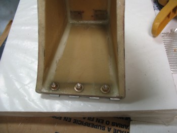
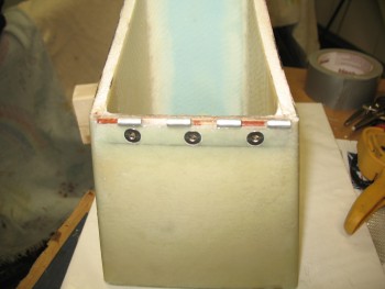
Finally, I floxed in the seatbelt bracket screws from the outside of the fuselage inward, and put a thin film of flox on the bottom face of the seatbelt brackets. I then bolted on all the seatbelt brackets (my buddy Kevin helped by keeping the screws from spinning on the outside of the fuselage while I installed the nuts from the inside).

•••
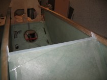
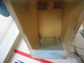
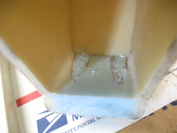
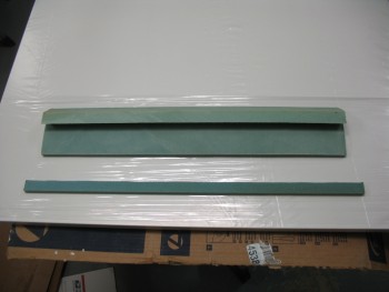
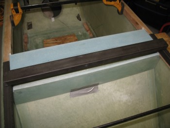
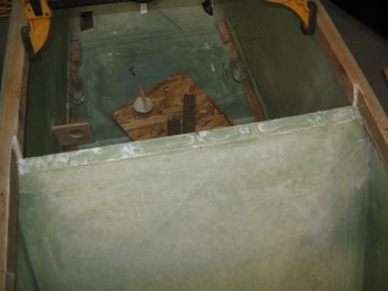
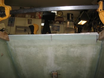
10 June 2012 — With the fuselage upright I had the opportunity to take a good look (and some pics) at the seatbelt mounts on the inside of the fuselage. . . let me just say: “These dogs will hunt!”
•••
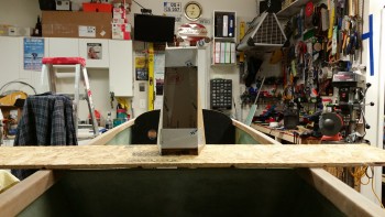
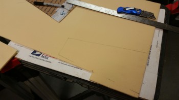
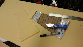
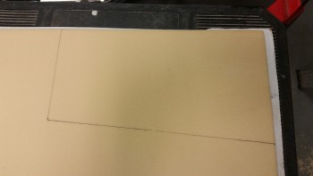
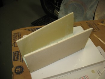
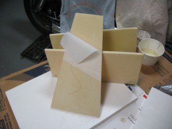
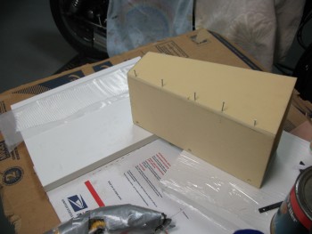
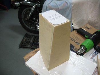
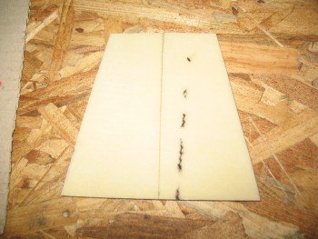
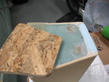
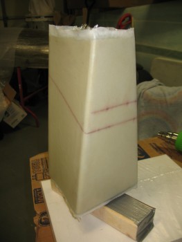
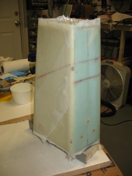
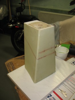
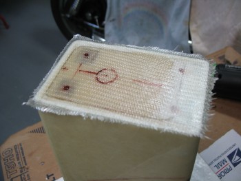
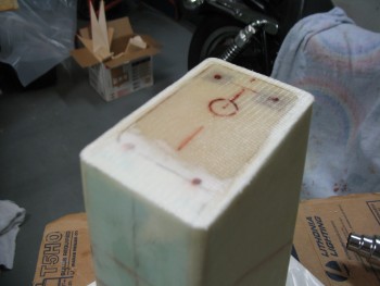
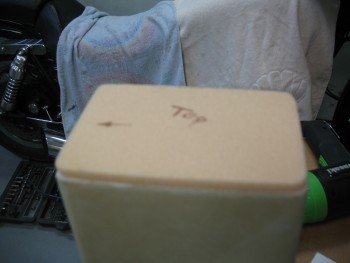
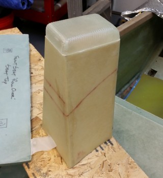
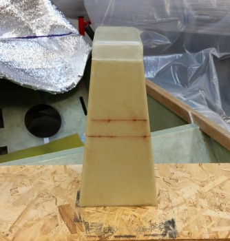
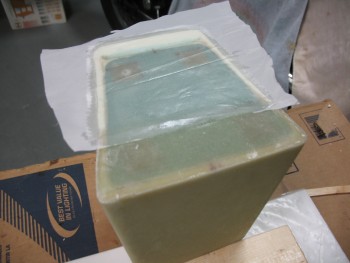
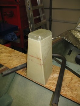
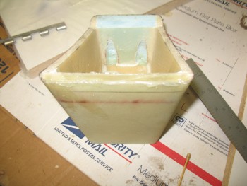
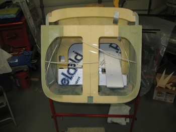
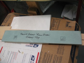
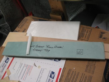
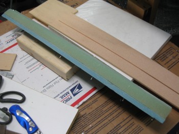
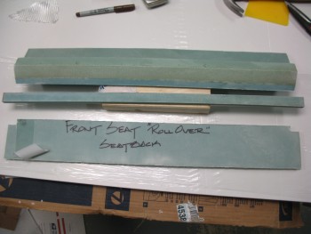
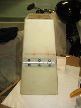
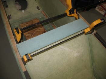
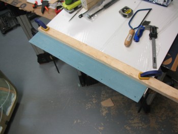
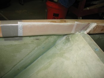
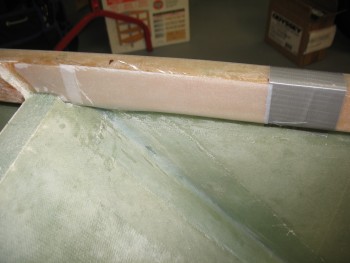
30 June 2012 — I needed to figure out the top of the front seat back. I don’t plan on using the traditional fiberglass triangular head rest / “rollover” assembly. I will however, have a base underneath whatever rollover structure I install, so I made some cursory mock-ups of the top cap for the front seat.
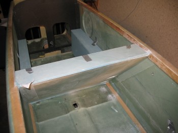
 After playing around with the front seat top cap (“rollover” structure base), I realized that no matter what, the front seat was going to be too high. It needed to come down at least 1.0″. A few more times looking at it and trying out different variants of a top-of-the-seat structure definitely convinced me that the seat back needed to be shortened, so I broke out the battery powered Skilsaw and a coping saw.
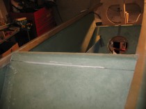
Although it was tough tearing into the first actual piece of this plane that I made, I feel that it had to be done and that the base for a metal rollover structure can be glassed in right under it.
•••
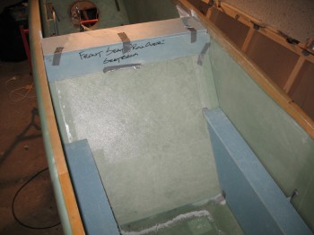
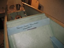
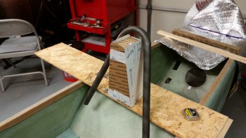
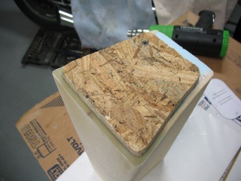
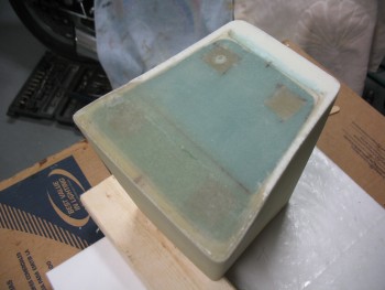
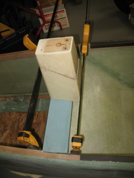
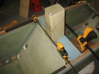
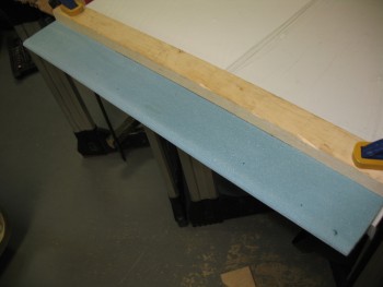
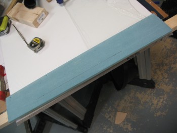
9 July 2012 — I grabbed a few more pics of the Chapter 8 top of the front seat back.
•••
31 December 2012 — Well, this will definitely be my last post for 2012 . . . it’s been a very busy year for this airplane build. Hopefully 2013 will be just as productive!
I’ve been playing around with the design for my rollover assembly. I’m looking to take a welding course while I’m in Tampa to focus on TIG (I already own Stick & MIG welders and have welded a fair amount) & possibly the EAA TIG welding workshop in Georgia.
In the meantime, as I mentioned I’ve been working through different designs on my rollover assembly, which I’ve included some scribblings on it below:
This is certainly not the final design I’m sure, but it gets me moving in the right direction and thinking about it.
Happy New Years!
•••
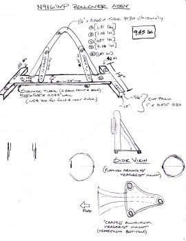
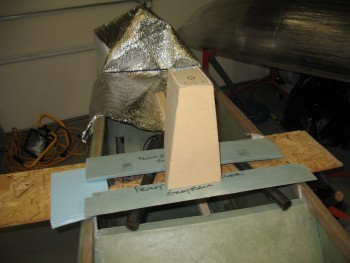
10 January 2013 — Below is a shot of my roll bar and my support down-tubes that will tie in the roll bar to the base assembly. I was originally going with a 0.1″ thick steel plate for the base that would travel from one longeron to the other, but that’s too heavy, especially if you add any cross support tubes to the mix (see my diagram with a couple square tubes under the steel plate). So right now I’m looking at having one rectangular-tubed cross support and taking my vertical support down-tubes from the back of the roll bar straight to the rollover assembly side supports on the longerons to eliminate a second/rear cross tube (which is the way many people build it). This will further eliminate some weight.
•••
1 March 2015 — Ok, I of course could have simply titled this “rollover assembly,” but the fact is I will have both: a rollover assembly for safety, which is essentially a 4130 steel roll bar, and also a headrest akin to the plan’s style headrest of years yore. However, the distinct difference is that my headrest will be as minimal as possible and allow as much clearance for the GIB’s unabated view as possible.
Why a headrest? There are 3 primary reasons I’m looking to incorporate a headrest into my rollover design scheme. I would say that the following list is actually in reverse order of importance:
1) Obviously the name: headrest. Not that I’ll be pulling so many excessive G’s so often that I’ll need a headrest, but I think it’s good to have one… especially when you need/want one.
2) Storage. In a small plane like the Long-EZ, you need all the storage you can get. Think of this headrest as a narrow tall box that is hinged at the top. In it will go the many things required for preflight and ground ops like a fuel sampler, rags, tie-down lines, mini-chocks, flight control gust locks/pins, etc.
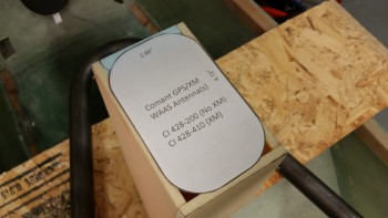
3) The Garmin GTN650 WAAS GPS stand. If you’ve happened to have installed a Garmin GTN650 recently, or simply read the installation manual, you will have noted that to reach the appropriate resistance (1.5-6 ohms) on the coax cable connecting the GPS antenna to the GTN650 head unit requires a cable length of 6.5 feet. Well, interestingly enough a cable run of 6.5 feet is spot on between the back of the GTN650 and the top of my headrest tower. In addition, the farther away it is from any electrical devices, the better.
A week or so back I measured the distance between the top of the longerons and the inside top of the canopy in the general position that I’ll have the canopy. With over 17″ of clearance for a rollbar, I figured I would go no higher than 15″, so I drew up a quick diagram noting all this.
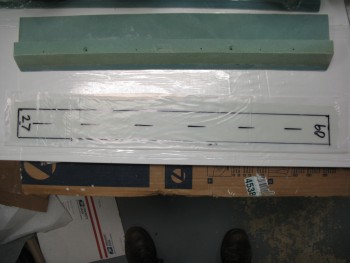
Fast forward to this afternoon when I pulled out the Plans and discovered that Burt’s original triangular composite rollover assembly is 12.7 inches tall. I took note of this since in order to save space, and maximize the view of the GIB, I really want to be in the general ballbark of the height of the plan’s rollover. For safety I of course want it taller than my noggin, but only as tall as it has to be, no more.
With the plan’s rollover assembly dimensions in hand, I started designing my version of the headrest. One set of dimensions that I knew right off the top was those for the WAAS GPS Antenna: approx 4-3/4″ x 3″. This clearly is no compact antenna.
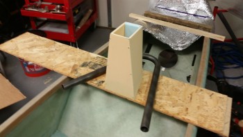
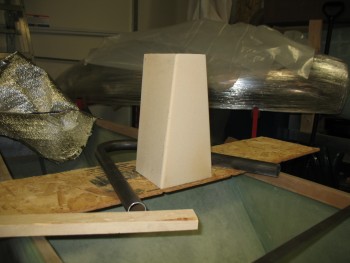
I had two simple overarching goals for the headrest: shorter & narrower then the plan’s version. I succeeded in meeting those goals …. sort of. My headrest tower is definitely shorter, but the top is clearly bigger since there’s a robust GPS antenna living up there. The base is significantly narrower, and even tapers narrower moving aft. With that being said, since I had 15″ of clearance, I started with an orginal height of 13-1/2″, about 3/4″ taller than the plan’s version. Of course I suspected I would shorten the model, but I wanted to see how it looked… and it’s always easier to remove material than to add.
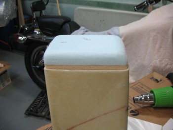
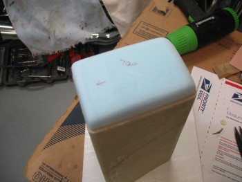
Here’s the initial cardboard mock-up of my headrest.
Without reference it looked rather tall. I eventually whittled it down to about 11″, but then realized I needed to judge its height with it under canopy. So I put the canopy over the 11-inch version if the headrest.
Moreover, I thought it might be a good idea that before I start glassing I should see how it relates TO MY HEAD. Since it will be, in fact, a headrest. The grand payback when incorporating any mod is of course time . . . and pain. So, using some simple risk management and avoid me toppling over inside the fuselage 3′ in the air, I needed to put it on the ground. Thus, half an hour later I climbed inside to see how big my noggin really is! ha!
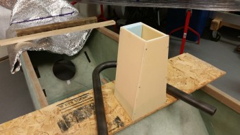
After messing about and playing the “I’m this tall” game with my hand against the top of my head going backwards (yes, I put the foam seat pad in place) I concluded that 11″ was just a tad too short [probably the perfect height would 12.7″… eh?!] and decided to add another 0.8″. Thus, my final height for the headrest is 11.8″ tall (0.9″ shorter than stock, but wider at the top), and 5.8″ wide at the base (vs 8.4″ wide stock) and 5.8″ deep (vs 4.5″ deep stock).
To really get an idea of the height, I Googled some pictures of the Long-EZ’s rollover assembly and watched a few YouTube videos to get a good mental baseline picture before I went final with the dimensions.
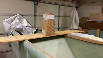
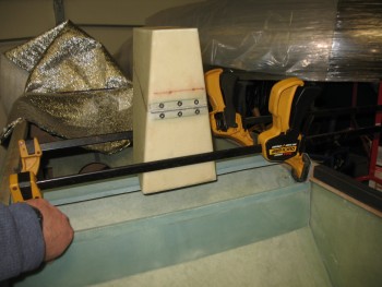
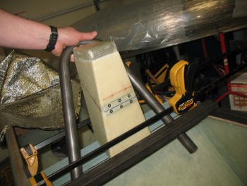
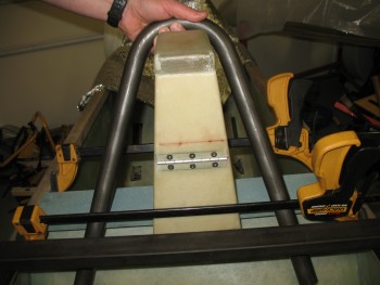
Also, to check out the very general appearance of my aft-leaning rollover bar that will encircle the rear top edge of the headrest, I balanced the rollover bar on the headrest mock-up.
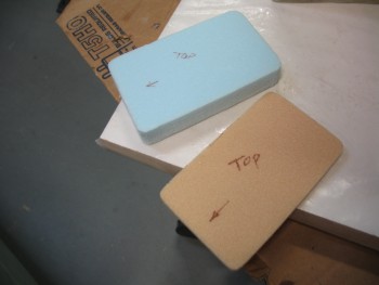
Satisfied, I then started cutting out the foam for the headrest. The front & sides will be 1/4″ thick foam while the rear will be 3/4″ foam, so that I can have much larger radiused corners at the back for a more “flowing” look:
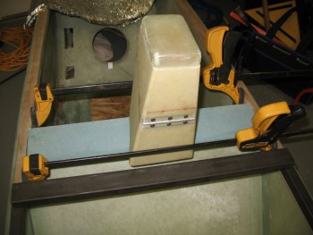
And here’s how the foam pieces looked when I pinned all the bits together with small nails:
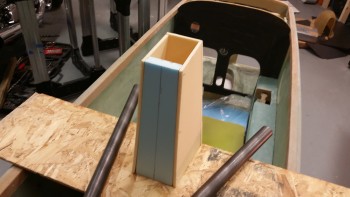
And lest we not forgot one of the main reasons for this exercise:
A tight fit, yes, but I wanted to keep the top as narrow & small as possible.
I’m pretty happy with this headrest. It will get the WAAS GPS antenna up where it needs to be, provide much needed storage and with the taper I have set I have a great view of the fuel site gauges and it it minimizes the view obstruction for the GIB.
•••
2 March 2015 — I started out today by picking out some good BID remnants for the layups on the interior surfaces of the headrest.
I then commenced to laying up 1 ply BID on the inside of the front face of the headrest. Since I’m not sure what all I’ll be glassing to it, I went ahead and peel plied the whole thing.
I had thought about just doing all the pieces separately and then assembling the headrest, but I thought since is my first real layup in almost 2 years, why not make it a little more challenging & interesting by laying up the 3 interior sides at once. So I micro’d the 2 side pieces to the back piece and held them in place with wood screws.
I used micro paste to fillet the corners and then laid up 1 ply BID inside the resulting “U” channel. After the glass was wetted out & looked good, I peel plied all the edges.
Step 1 of the headrest complete!
•••
3 March 2015 — Tonight I razor trimmed pieces, pulled peel ply & cleaned up the peel ply strings from the headrest layup. After the layups cured, I was left with 2 assemblies: the front piece and the two sides/back wall as one unit.
I then dry fitted front to right side wall assembly… doing one side at a time to minimize complexity. I drilled holes for nails and preset those before glassing.
I then mixed up epoxy, micro’d the front wall piece to the right side wall piece, set with nails, cleaned up the exuding micro & then taped up the joint tight.
I used fairly thick micro paste to fillet the corner, and then pre-pregged 1 Ply BID corner tape just a hair under 2″ wide so it would fit under 2″ peel ply tape.
After the corner was laid up I peel plied it with the 2″ wide tape.
I also rough measured, cut & laid up two 1/4″ foam pieces with 1 ply BID for the headrest base and GPS antenna shelf. I threw some peel ply on these last pieces and called it a night.
•••
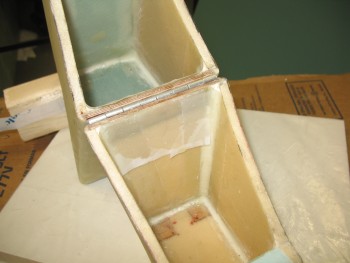
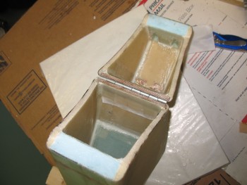
5 March 2015 — Today I took all the clamps off the cured headrest box. I will state for the record that building a complex shaped box without the use of jigs may have quelled my inner artist, but it didn’t make for a perfectly shaped box. Not bad, but the sweep (or swoosh!) on one side of the box from the front corner is slightly different than the other side. A symptom of having glassed the front face to the rear part of the box one corner at a time.
Anyway, I tweaked it with a myriad of clamps and will work on it just a bit more to massage the shape. Regardless, here’s a couple shots of the completed headrest box structure. Note that the top shelf insert for the GPS puck is just wedged into place and not glassed yet. I will need to insert some small hard-points for the GPS puck screws to be fastened to. In fact, in the second pic you can see the markups I did for the puck screw points & cable access hole.
A couple of days ago I showed a pic of my glassing the foam for the GPS puck shelf and the headrest base, which I shaped to size below.
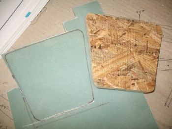
This headrest base–made of 1/4″ foam–would prove to a trooper that fought valiantly to stay in the game, but alas, it succumbed to the intense heat of my heat gun and warped as I was bending the headrest tower to my will. As I hunted around for some more material, I ran across a scrap piece of 3/8″ Divinycell foam that was already glassed on one side.
Moreover, since I had ginned up a base mock-up out of OBS flooring board, I was already in the frame of mind for something just a tad thicker and robust than the 1/4″ foam base. After playing around with the shape for about half an hour, I transferred the actual wood base mock-up outline to the 3/8″ foam.
I then cut out some small square hard-points out of the Finnish Birch 1/4″ plywood that is used for the firewall, etc, after I decided where my headrest attach bolts will go.
I floxed the plywood hardpoints into the holes that I made in the headrest base, and then covered each piece of plywood with about 12 plies of BID to fill up the remaining 1/8″ of space so that the hardpoints would be even with the face of the foam. I then laid up 1 ply of BID over the entire piece of foam & peel plied it.
I set the headrest base aside to cure overnight and called it a day.
I guess here would be a good point to digress & explain why I have bolt hard-points in the base of my headrest. It all stems from the design of my 4130 steel rollover assembly, or simply the roll bar. Since the main roll bar wraps around the back of the headrest tower, AND the front 1-3/4″ of the headrest tower actually sits on the rollover crossbar, there’s no way to hard glass the headrest to the base of the pilot’s seat and still have the rollbar removable (which is a design feature I would prefer to have)… since they’re interconnected. A bolt-on headrest also allows for much easier future mods (if I decide to make any). Or I can replace the whole thing with a super swank version later on if I so choose!
•••
6 March 2015 — Today I focused on tweaking the shape of the headrest tower to get it as close to symmetrical as possible. Because of the design, it’d actually be somewhat difficult to see my slightly lopsided headrest assembly. Nonetheless, I still wanted to get everything as balanced as I could. I spent about an hour sanding the tower and was pretty darn happy with how the symmetry came out.
 With the shape locked in, I worked on the GPS antenna puck shelf to install the hard-points that will keep the GPS antenna nice and secure. As you can see in the picture below, I had 2 pieces of 1/4″ plywood marked off and cut the first one no problem, but when I cut the second one, it flew off into the bowels of the garage, not to be found no matter how much cussing and moving things around ensued. Thus, I grabbed the next piece of plywood available, which was slightly smaller than the other one. In my mind, here’s where NOT sweating the small stuff comes into play. Thus, to save time, material and frustration, I simply embedded different sized–albeit capable–pieces of plywood for the hard-points. I’m sure stuff like this drives the OCD’ers crazy, but that’s why I revel in not being OCD!
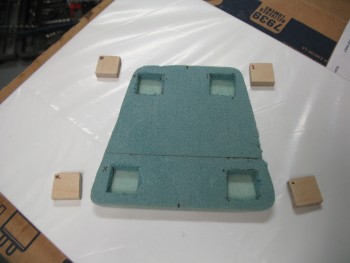
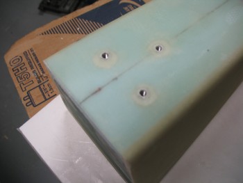
My next task of the evening was to embed 3 threaded aluminum bungs into the back of the headrest to attach a RAM ball mount for the GIB. I climbed into the back seat to get a good idea of what level the RAM ball mount should be attached. Once I had that info in hand, I set about setting up the RAM mount to install the threaded aluminum bungs.
I started by cutting the 1 inch long aluminum threaded inserts (ala the Cozy Girrrls) in half since the foam is not thick enough to allow for the full length of a standard insert (aka “bung”). After cutting them, I prepped the RAM ball mount by wrapping it with packing tape. Once protected from the flox I would be using to hold the threaded aluminum inserts, I made 3 holes into the foam down to the opposite-side glass. I then screwed the bungs to the RAM ball mount securely. After mixing up some flox, I poured it into the 3 holes about halfway, then I embedded the 3 bungs attached to the RAM ball mount into the flox and let cure. Below shows all this post cure.
And with the ball mount placed to show the final spacing.
•••
7 March 2015 — Today I cleaned up the layups on the headrest base piece and the GPS antenna shelf.
One issue I needed to address is that the front face of the headrest was a little off from straight vertically. With the headrest on a flat surface, using a square I could clearly see that it was a few degrees less than 90°. After a bit of head-scratching, I decided to simply add a few layers of BID to the front third of the headrest base, in a stepped fashion.
As far as the antenna shelf, I added hard points for the front screws, but the rear screws are actually located right on the edge of the antenna shelf insert that I just glassed. So I Dremeled out the foam in about a .6 inch diameter half circle for each point where the rear screws go through. I mixed some flox up and poured it into my prepared foam edge hard points. Since I had extra flox leftover, I filled in the remaining gaps around each of the 3 threaded inserts for the RAM ball mount. You can see this in the pic below:
•••
8 March 2015 — Today I finalized all the prep for glassing the headrest. While I’ll still need to glass the GPS antenna puck cover, once I finish this next layup the majority of the glassing on the headrest will be complete.
I had deformed the blue foam a bit at the top of the headrest when I was using the heat gun to better align the headrest. The heat gun worked but, as often is the case, not without collateral damage. No worries. That’s the great thing about composites: with just a little more time, you can fix nearly every mishap that may occur along the build process.
So to fill in the significant imperfections I used a page out of Chrissi & Randi’s (aka “The Cozy Girrls”) build book and employed some Super Build Micro! I actually don’t know what they call it, but I needed a catchy name to set it apart from just plain-Jane micro.
First off, be forewarned that this micro is nothing more than filler & is merely used as very light matter to occupy space. It is NOT meant for anything requiring structural strength. If done correctly (and mine was just so-so) it is reportedly really easy to SAND, so you don’t tear up sensitive foam whilst sanding hard cured micro.
How is it made? What’s the secret ingredient you ask? Well . . . it’s . . . ALCOHOL. I mixed up a batch of really thick micro, then I add a little bit of rubbing alcohol, then that re-liquefies the micro paste into micro slurry, whereupon I added more micro until it was really thick paste again. Then a little bit more alcohol, then some more micro, etc.
Obviously what you get is a product analogous to auto paint in that it is laced with a reducing agent. As the paint cures, the reducer evaporates and lets the paint solids cure into a hard shell. In reality, this is more along the lines of what happened with this micro. The build micro is supposed to be easy to sand, but although it did sand easily enough to keep me from tearing up the foam, it was still a bit of a chore. It probably took about an hour total to sand all the micro to the shapes and levels I wanted.
Here’s a pic of the build micro applied to the areas needing it on my headrest.
And here’s a picture after I sanded the excess micro and shaped it to match the shape of the headrest.
Here’s a side profile view of the top aft corner that was in such a bad way before I started.
With all the holes & dings filled and sanded, I finally had the headrest ready to glass. I had used only BID scraps up to this point, but I wanted a nice finish for the headrest tower with no overtly noticeable glass seams, so I used my new glass cutting table for the first time to cut 2 pieces of BID out.
My plan is to glass 2-plies of BID on the front & sides, and then have all the overlap/extra plies ending at back of the headrest.
I cut 2 BID pieces 13″ x 23″ in the ballpark of a 45° bias for strength.
With the headrest ready for glassing and the BID waiting to be applied, I’ll tackle this decent-sized layup tomorrow since it’s getting late.
•••
9 March 2015 — I started off today by mounting the original wood piece that I used to mock up the foam insert for the headrest “floor” as a temporary glassing base. Since its overall dimensions are smaller than the overall dimensions of the entire bottom of the headrest, it will allow the glass to overhang the foam while curing.
I drilled a pilot hole into one of the rear hard points and the temporary base, then mounted the base with one screw to the bottom of the headrest.
With the temporary base complete, I was ready to get to laying up some glass. I did one final vacuum of the surface and mixed up my epoxy with about 2/3 slow with about 1/3 fast hardener to give it about 4 hours until it was solidly cured.
I microslurried all the foam & then proceeded to glass the entire exterior of the headrest’s 4 vertical walls. I started with about a 1″ overlap on the rear face, wrapped 1 ply of BID all the way around the headrest and ended up on the corner where I started. This of course gave me a 1″ overlap on the glass.
I then did the same thing on the opposite corner of the rear face, only going in the other direction. Since the blue foam is a little softer and less dense then the yellow foam, I decide to give it all the extra “hangover” plies to give a essential provide the majority of the rear face with 3 plies of glass, with only about a 3/4″ strip near the center of the rear face being left with only two plies.
 When I was done with the actual glassing, I peel plied the entire layup with one piece of peel ply (technically I needed one extra small triangle of peel ply to cover the top rear corner, as you can see in the pic above).
With the layup looking good and the glass edges trimmed back to about 1/4″, I set the heater facing it (on low) and let it cure overnight.
•••
10 March 2015 — I had a little time this morning so I tried to knock out as much as possible to prep for the GPS antenna puck cover build later this evening.
I went downstairs to find that the glass was nice and cured. Unfortunately, I found about 4 decent sized delam “bubbles” as well. I say bubbles since they’re pockets of air, but there was no real surface deformation of the glass. No worries, a few shots from Dr. Inject Epoxy and they’ll be fine. Sometimes I think heater air on a layup can be a double-edged sword: the layup can cure faster, but I think it can facilitate off-gassing as well causing some delams.
I razor trimmed the excess glass and pulled the peel ply to find the surface nice and uniform. Besides a few delams, everything else looks great.
I then turned my focus onto the threaded inserts that were embedded for the RAM ball mount. Starting with a TINY drill bit, I very carefully drilled out the glass covering the holes over the each threaded insert. A lot of builders have a lot of different techniques for covering holes, or filling them, to protect the threads during glassing. I simply put a very small, square piece of duct tape over the hole, just barely big enough to cover the hole. Then when I drill out the hole, it usually grabs the tape enough to rip it out of the layup so I’m left with a very clean access hole to my threaded inserts.
 Of course I had to test out my handiwork by quickly mounting the RAM ball mount.
With the RAM ball mount threaded hard points good, I started working on the GPS antenna shelf. Since there’s bare foam on the edges, I want to trim away the foam in the corners to make a nice micro corner. I’m concerned about the strength of the corner itself, not the entire headrest structure so I’m only using micro (vs. flox).
 I’ll lay up 1-ply BID across the entire top of the headrest to get it all uniform and capped off. I then test fitted my BID.

And then mixed up some micro using fast hardener & micro’d the edges of the glass/foam junctions at the top of the headrest (sorry for the blurry pic).
And then laid up 1 ply BID on the headrest top that will serve as the GPS antenna mount.
Later in the day, I knife trimmed the antenna mount layup while it was still just barely pliable, and then set to work on the hinge that I’ll use when I finally turn the headrest into its secondary purpose as a storage box. You may have noticed the diagonal lines on the side of the headrest. These lines are the cut lines so the top will hinge-open forward to allow me to store stuff inside. Thus, the hinges will be on the front face of the headrest and hidden from plain view by the headrest pad.
After spending some time on the hinges, I finished trimming & sanding the edges of the fully cured GPS antenna mounting shelf/headrest top.
With the GPS antenna mount glass cured, I started in on making the GPS antenna cover that will cap off the top of the headrest assembly. Since the GPS antenna is 0.9 inches tall, I wanted the interior height of the antenna cover to be about 1.05″ high. Well, I simple added a piece 0.8″ thick blue foam to 0.25″ thick yellow foam, and 1.05″ thick…voila!
I started with the yellow foam as the base of essentially a plug for the antenna cover. I shaped the yellow foam to match the top of the headrest, minus the approximate width of 2 plies of BID. I concentrated on ensuring the angle at the back of the cover matched the angle of the back wall of the headrest.
With the base finished, I then went into artistic carving mode on the blue foam, keeping Burt’s eternal words running through my mind: “Carve to a pleasing shape . . .” First, I simply screwed the thinner yellow foam to the blue foam with 4 small screws.
Then I again concentrated on the back side of the antenna cover to now make the blue foam match the angle on the 1/4″ yellow foam.
It took about a half an hour of carving, shaping & reshaping, but I eventually came up with a shape that was pleasing to me & would serve nicely as a GPS antenna cover. I mocked it up on top of the headrest to see how it looked. Looks good…time to get ‘er glassed up!
I quickly assembled a glassing stand for the antenna cover plug to get the plug at a better working height and to allow the glass to hang straight down from the sides of the plug without any interference.
 I then unscrewed the thinner yellow foam from the thicker blue foam, screwed the yellow foam to the glassing stand, and then remounted the blue foam to the yellow foam for a solid glassing base.
My next door neighbor & good friend Dave came over while I was getting all this set up, so I was remiss in getting any more pictures until after I was finished wetting out the glass and making sure the layup was complete. Again, I simply used 2 plies of BID for the antenna cover.
You can also see that I taped up as much of the plug as possible without creating any surface irregularities to enable a better release of the glass from the plug after it cures.
•••
11 March 2015 — I didn’t do much on the build today since I needed to focus on some real estate training and my Instrument pilot class.
I did do a real rough cleanup on the GPS antenna puck cover edges while it was still on the plug. I actually popped the GPS antenna cover off the plug while it was just freshly cured late last night, then I taped it back onto the plug so it would keep its shape as it fully cured overnight. It was definitely much more rigid today when I pulled it off the plug after razor trimming and sanding the edges.
Also, after I pulled the cover off the plug I cleaned up the inside corners that had some residual foam still attached. Of course I had to place it on top of the headrest to see how it fit and get a few pics.
•••
13 March 2015 — My goal for the evening was to embed the hinge halves into the top & bottom of the headrest (you’ll see what I mean below) along with the associated 1/4″ plywood hardpoints. I had originally drawn the cut lines on the side of the headrest as simply straight diagonal lines, but after thinking on it more I realized that both the front & rear faces would need to be cut straight. The front required a straight cut for the hinge installment to be optimized and the rear face needed to be cut straight because I want to install some type of lock mechanism onto the back of the headrest to allow me to secure a few small things while away from the aircraft at fly-ins, etc.
Thus, I rewickered my original plan(s) & redrew the cut lines.
I then got out my trusty Fein saw and went to work.
The cuts were a little tougher to make at the corners than I expected due to the micro fillets, making them all just a little bit rougher & less razor-straight as I wanted them to be.
Of course they’re still perfectly workable & the lines looked good when I put the two halves back together.
Again, my goal was to embed the hing halves, but then I realized there was some more pressing, less sexy glassing that needed to get done. Both the top antenna shelf and the bottom base pieces required some micro fillets in the corners and some BID tapes to finalize the installation of these pieces.
As I started prepping the layups for the top antenna piece, I came across another minor issue that I needed to resolve: the location of the rear mounting screws for the GPS antenna falls right on the edge of the inside, rear face of the headrest. Since the rear foam is 0.8 inches thick, it’s in the way of the rear two screws securing the GPS antenna puck to the top antenna shelf. Clearly I needed to remove some glass & foam to give room to the hardware securing the antenna to the headrest assembly. I at least wanted to account for this issue before I glassed up all the inside corners underneath the antenna mounting shelf.
I started by drilling a tiny hole on the top side of the antenna shelf at each hardpoint where the two (2) rear screws would hold the GPS antenna to the shelf. Then I drew a couple of rough outlines for the underside shelf hardware access points.
 I grabbed the drill with an 1/8″ drill bit and made a series of holes along the marks I just made.
I then used my razor knife to cut out the fiberglass outlined by the marks.
Once I cut out the fiberglass wedges, I used the small round Perma-Grit tool to create a “scoop” that would allow access to screw hard points.
With that out of the way I began glassing the corners of the underside of the antenna shelf. I started by whipping up some thick flox & laying it into the “bottom” (turned upside down) of the screw access point divots that I just created. With very little flox left, I added more epoxy to that cup and dumped in a bunch of micro to use for the corner fillets. Before I started mixing any epoxy, I had selected a good-sized piece of BID and cut out a bit of plastic in order to pre-preg the corner BID tapes.
I got the corner micro fillets in, wetted out the 1-ply BID in the pre-preg setup and finished up the layup for the inside front, left & right sides, and the middle corner piece between the 2 new hardpoint divots. I set it aside to cure, which is the picture below a few hours later after I cleaned up the excess glass at the edges of the hardpoint divots.
 While the antenna shelf corner tapes layup was curing, I essentially did the same thing for the interior side of the headrest base. I whipped up some micro for the corner fillets, and then pre-pregged 1 ply of BID for the corner tapes. Since I had a little more room to work, I cut a 1″ peel ply tape strip in half and peel plied some potential prickly barb areas along the front side tape and the right side tape. The pic below is after it was all cured and the peel ply pulled.
So although I didn’t complete what I set out to, I got the “mundane” stuff out of the way and will work on the hinges next.
•••
14 March 2015 — I remembered another “mundane” thing that I needed to do before I actually get to installing the hinges, and that is to finish the very bottom of the headrest by adding 1 ply of BID to the face of the base to cover all the exposed foam and to further connect the base piece to the headrest sidewalls at the aft half of the headrest base.
I started by cutting the foam out along the edges to create micro wedges to reinforce the corners. Again, if this was a piece that I wanted to have higher structural integrity, I would be using flox. But since I want to provide added strength at the corner edges while still keeping it as light as possible, I’ll be using micro.
I of course got over halfway through getting the micro into the angled troughs I had made when I thought about taking any pics of my progress.
 Since I previously added a number of plies to the front half of the headrest base to get it to sit level, I will simply overlap the last ply of that previous layup with this piece of BID.
 After wetting out the BID I of course trimmed the edges down to about a 1/4″.
 And as is my MO, I added peel ply.
 So here it is in its trimmed & completed glory.
 And here’s a quick shot of the headrest up to this point.
Now, I should seriously be able to get to the headrest hinges on my next build session!
•••
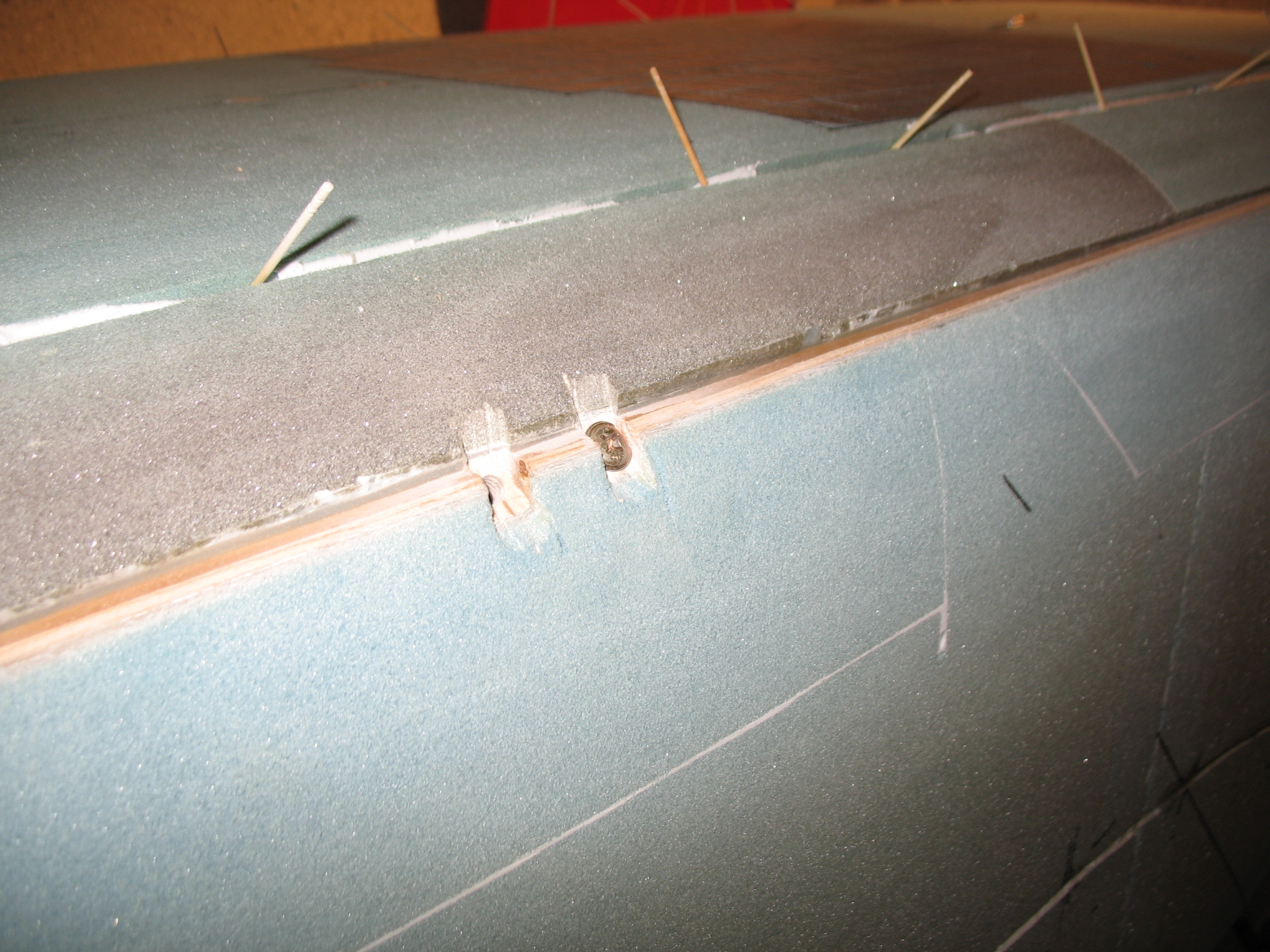
15 March 2015 — Today I finally finished installing the hinge on the front face of the headrest. I started by digging out the foam from the hinge mounting area on the top part of the headrest.
I dug out as much foam as I could using the razor knife and then I switched to using the Dremel tool.
As I got the foam dug out to the proper depth it was obvious that both the plywood insert and the hinge flange would not both fit width-wise, so I shaved a few more layers off the plywood by the approximate width of the hinge flange. I had already shaved off a couple of layers off the plywood previously, but it clearly required another thinning.
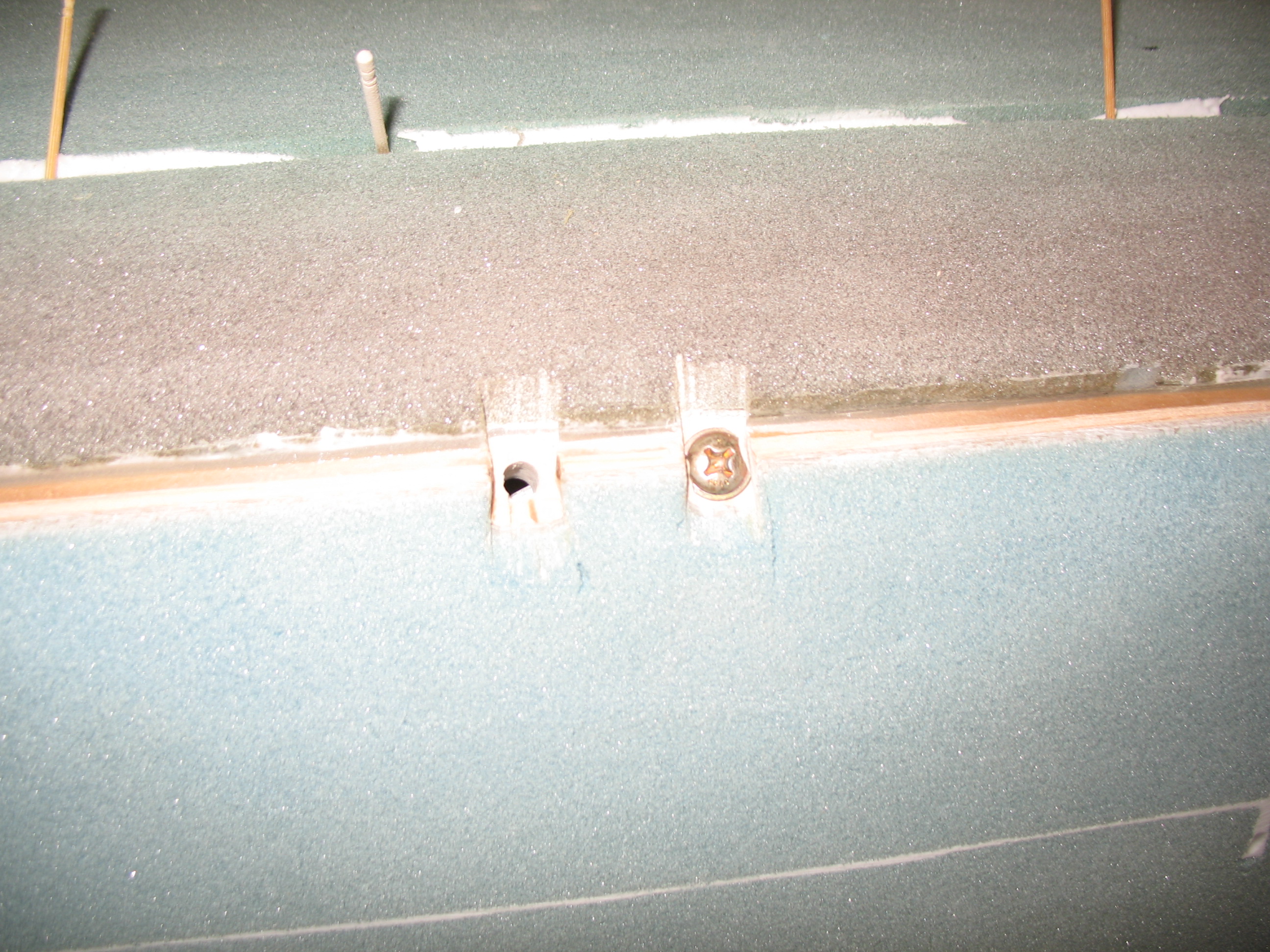
Before I thinned the plywood insert, it was so tight that I had to add tape to it in order to remove it.
I measured the hinge barrel width at 0.180 inch, so I simply halved that to remove 0.090 inch from the outer glass layer on both the top & bottom hinge mount, to center the axis of the hinge along the line between the top and bottom parts of the headrest.
Below you can see where I cut out 0.090″ for proper hinge positioning.
After mocking up the plywood insert & the hinge flange to ensure a proper fit, I mixed up some flox using fast hardener and slathered it into the hinge area.
I also cut 4 pieces of duct tape to protect the holes at each end of the respective tabs on the hinge. I then inserted the plywood insert & the hinge into the slot that I created on the front face of the upper portion of the headrest.
While the upper headrest portion’s hinge assembly cured, I started prepping the hinge area on the lower headrest structure.
I tested the width & fit of the plywood insert in the same way I did on the upper headrest structure. The plywood insert for the lower headrest structure needed to be thinned down as well.
As I was ready to pull the trigger on the lower hinge, I double-checked the first hinge assembly.
Having used fast hardener & then putting the heater on it had it cured in no time flat.
Since the top hinge half was cured in place, I used it as a template for the bottom to get a near-perfect fit. I taped a strip of packing tape across the abutting plywood inserts. I then floxed in the lower hinge and gave it about 20 minutes to cure before I mounted the top hinge half to the bottom hinge half.
After ensuring that no unwanted flox was getting into places it wasn’t supposed to, I ensured the upper & lower headrest assemblies were aligned. I then taped the parts together with duct tape and to minimize any gaps I weighed down the entire structure.
After 30 minutes passed with the headrest in front of a heater, I removed the tape and weight to check the rotation of the hinge, and to make sure that there was no flox gumming anything up. There was a few bits of flox here & there that I removed with a toothpick, but the hinge rotation was great and all looked good.
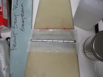
Here’s a quick video discussing the headrest hinge:
•••
16 March 2015 — Today I awoke to what was supposed to be a nasty day, but turned out to be a beautiful day for flying. I was getting together with my lifelong friend Kevin, who stayed with me a bunch in Germany and helped me glass the left wing. Kevin just got back into town permanently after having done the multi-year contractor gig over in Pakistan since about the time I was returning to Germany from Tampa in April 2013. Long story short, I took him flying on a hop over the Chesapeake Bay to Cambridge, Maryland where we did a few touch-n-goes and a couple of landings before heading back. Amazing how a forecasted crappy day turned out to be almost as perfect as you could ask for to fly.
Back in the shop, I went into planning mode. With just a couple small odd-n-end things to do on the headrest, I turned my sights to the seat back configuration. As I said in my video, the seat back will be close to the original plans in that there will be about a 4″ wide glass shelf, or headrest base, that meets the seat back at the aft side, will traverse across the fuselage from longeron to longeron, with the forward edge abutting the rectangular 4130 steel crossbar that will make up the primary base of the roll bar. The rectangular crossbar is 1.75″ wide, so add that to the 4″ glass base that sits directly aft of it, and we get an overall flat surface area going across the back of the seat of 5.8″ wide.
Coincidentally (or not), the headrest assembly is 5.8″ deep at the base. I don’t have any pictures of all this yet, but you can see that the aft 2/3 of the headrest will sit on the 4″ glass base, with the forward 1/3 of the headrest sitting on the rectangular crossbar. Two (2) screws will secure the headrest to the glass base, and two (2) screws will secure the headrest to the rectangular crossbar, for a total of 4 screws securing the headrest to the base structure of the seat back.
So tonight was all about figuring out the composite structure for the seat back area. If you take Burt’s original headrest configuration, and lopped off the triangular headrest so that you were just left with the base of it, you would essentially have what I am designing right now. One other key modification that you would have to do to the original plan’s seat back, is to make a notch 1″ down and 1.75″ deep/wide at the front corner of the plan’s headrest base to allow for my rectangular metal crossbar to fit in there.
I accounted for every piece I was going to need, while assessing the pieces I had already made during the Summer of 2012 in Germany. I will also need to widen one of my 3/8″ foam pieces that I have glassed on one side, and cut out some foam pieces that will be wide enough to go across the fuselage. I pulled some 3/4″ & 3/8″ sheets of Divinycell out of storage in preparation for the seat back construction and confirmed I had all the materials required on hand.
Obviously once I get the headrest base/seat back glassed I can start actually welding the 4130 steel rollover assembly together.
My goal is to have Chapter 8 completed by the end of March 2015.
•••
17 March 2015 — This morning I knocked out the BID reinforcements for the hinge screws on the internal side of the headrest. I used 2 plies of 1/2″-wide BID for the main reinforcement on each side, then followed that up with a 3/4″-wide layer of BID for both a final third ply for strength and as a transition to existing glass. Since I pre-pregged these BID tapes I had 2 separate pre-preg setups: one for the 1/2″ tapes, and one for the 3/4″ tapes. Here’s the 1/2″ tapes I started off with, each with 2-plies of BID:
Here are the hinge screw reinforcement layups finished & peel plied:
I had to run out and do a bunch of errands, so when I got back home I started on the seat back build. I’m going to jump ahead here to my final layup of the evening, which was adding a 1-ply reinforcement BID tape for the hinge screws on the external side of the headrest on the front face. I had some epoxy left over from the layups below, and had already been kicking around the idea of adding a ply of BID since I really want to counter sink the screws flush on the front face. I figured I would give the screw heads just a little bit more meat to grab onto.
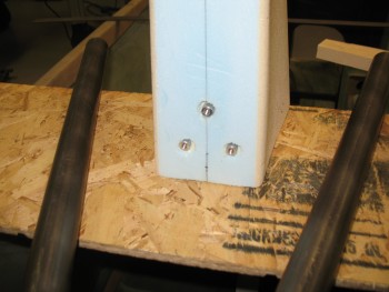
With my reinforcement plies of BID in place on all sides of the hinge, tomorrow I’ll install the 6 screws, washers and nuts to the hinge assembly.
My first order of the day for the seat back composite assembly was to cut out some of the required foam I needed. Since the base of my headrest and rollover assembly is a total of 5.8″ wide–versus 4.5″ stock–it requires that I add a little height to my very front foam piece that makes up the seat back as it dives into the existing seat… the piece that makes up the lowest installed component of this whole assembly. I had originally made that piece to stock dimensions out of 3/8″ foam. I had also glassed it with 1 ply of BID on one side. Now to make up for it moving forward slightly, and thus down the seat face slightly, I need to add a 0.7″ wide strip of 3/8″ foam to the top of it.
I cut the 0.7″ strip of 3/8″ foam & then quickly positioned it to ensure I was on track. As you can see from the pic below, I’ll have to fill in the notches that were originally meant to allow clearance for the longerons.
I then marked up the 3/4″ piece of foam that I would use to fill the gap from the existing front seat top & the 3/8″ thick foam cross piece that makes up the base of the headrest, somewhat like the original plans headrest base that is essentially a shelf that traverses the seat back from longeron to longeron.
I then took the 3/4″ foam and piece of 1/4″ foam that I’ll be using and cut them on my table saw. Here’s the resulting piece that I’ll use to fill the gap for the seat back, set in place.
You may note the clamps in the picture above being used as expanders for the fuselage. Since my fuselage is a bit more curved than a stock fuselage, and since I also cut the top of the seat off in my original plan for the seat back & rollover design, the front seat has developed a very slight curve forward in the middle. I put those expanders in and have been increasing the pressure every few hours as I was getting ready to post cure the seat to straighten out the seat back as much as I can.
I prepped the seat back for post-curing by getting the nose as high as possible so that the weight would be concentrated on the seat back. Since I don’t have my workout weight set here with me, I had to resort to hunting around for some fairly heavy objects, thus the weird sight below of an old sub-woofer and the quite hefty front forks for my chopper project (that were damaged in the move btw).
I put some foam insulation heat shields at the front of the fuselage to trap as much heat as I could.
Then I placed my trusty shop heater in the back seat on a small piece of plywood, and covered the fuselage with the same material I used in Germany for the massive 24-hour Uber fuselage post cure.
With the fuselage covered and the seat back (hopefully!) getting realigned back to where it should be as it baked at almost 120° F (see pic below), I started in on glassing the 0.7″ strip of 3/8″ foam and the top of the seat back to the spacer that will fill the gap on the existing seat.
I started by pulling the peel ply off the seat back base piece. I glassed this thing back in the Summer of 2012, and the peel ply still came off quite nicely. Also, I am actually using this piece upside down compared to how it was originally meant to be used.
I mocked up the gap-filler piece to the seat back base, and then when I liked what I saw I pinned it together using finishing nails.
Here are the 2 parts of the seat back that I’ll be glassing tonight: a) the 0.7″ strip that will be added to the back rest piece, and b) the seat back base with the gap filler.
Now, I’ll let you in on a dirty little secret of mine. I have yet to touch any of my new MGS 285 epoxy. Since I don’t consider the headrest as a structural piece, I’ve been using the 4 year old MGS that I had originally left with Marco. I have to tell you, that old MGS 335 is still kicking and I see no diminished effects in strength or hardness.
Thus, I broke out a new can of MGS hardener and prepped it in one my squeeze bottles. The pic below doesn’t do this stuff justice in how brilliant the blue is for the MGS 285 hardener. It really is stunningly brilliant stuff.
 Now, I will say the big difference between that old stuff and this new MGS 285 (which is a significant difference between MGS 285 and 335 anyways) is that the 285 is a dream in its usability. It flows like water & it wets out so amazingly well. It’s like the difference between driving an old reliable truck or a beautiful sports car. Both work and do what they’re supposed to, but one drives like silk…. as does the MGS 285. Great stuff!
As for my layups, I started by applying microslurry to the 0.7″ strip.
Then laid up 1 ply of BID:
And then peel plied it.
I then started on the seat back base & gap filler.
I mixed up some flocro (micro with about 1/2 flox) to attach the gap piece to the seat back base.
After messing around with ensuring the pieces were aligned & all the excess flocro was removed from joining these pieces, I laid up 1 ply of BID on what will be the back side & top of the back seat, something along the lines of the rear top corner of a “7” . . . of course including the top of the “7” as well.
Below were the 2 “to-do” items on my list tonight, now glassed and curing:
Tomorrow I’ll check the outcome of my post cure on my seat back, and then also start cutting some 4130 steel in preparation for the mock-ups and fittings required before I can finalize any layups on the composite seat back structure.
•••
18 March 2015 — I started off today cleaning up the layups I did yesterday on the seat back shelf/headrest base & the lower seat back 0.7″ add-on piece.
I then pulled the peel ply on the lower seat back piece & cut out 2 small rectangular pieces to fill in the notch on each upper corner that originally allowed for the piece to set up tight against the longerons (basically the stock style seatback piece that gets glassed to the seat back at the lowest point of this whole endeavor).
I then went scrounging through my old BID pile to find 2 acceptable pieces of BID to use for these next two layups. I’ll pre-preg the 1-ply BID for the underside of the upper seat back shelf where it joins the gap fill piece that will make up the new top of the seat (replacing exactly what I cut away a couple of years ago!).
I started by micro’ing all the pieces (4 total) of the lower seat back, covered it with saran wrap and then weighed it down to hold it’s shape (you can see it in the background below covered with a veritable smorgasbord of chemicals!). I had already wetted out the pre-preg when I started on the lower seatback piece, so I then used the small amount of leftover micro & added a boatload of flox to it to make up the fillet for the seat back/gap fill piece.
I did a final prep on the 1-ply BID pre-preg, cut it to size (2″ BID tape) & then laid it up.
Here’s the final layup, peel plied and curing.
With the micro on the lower seatback piece significantly more gummy, I laid up 1 ply of BID on what was 4 completely separate parts just a half hour ago.
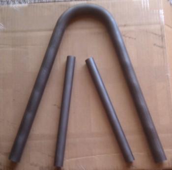
I then went into a completely different direction, breaking out the 1 x 1 inch square 4130 tube that will serve as the side rails for the roll bar assembly. I know a fair number of my compadres use a rectangular piece to start so that they get a full 1-1/2″ coverage on the entire inside of the longeron. But I really want to save as much weight as possible on the rollover assembly (ok–everywhere) and lopping off a 1/2″ strip of 4130 steel on a run of about 24″ will help quite a bit. I may be somewhat more sensitive to saving weight on the rollover where I can–without compromising safety–since I’m adding well over a pound of weight into the mix by actually having a headrest.
The advice I got from Marco on cutting this 4130 steel was to use my table saw with a cutoff wheel, which I will most likely do for the 4130 steel that I’ll be using for my engine mount extrusions (vs 2024 aluminum… at least on the top mounts). With it being a very windy day, and with the amount of energy I have to expend on pulling my table saw out of the external shed, change the blade, etc. I chose to go into true experimental mode (read: lazy) and use my Dremel Tool with a cutoff wheel to rip the square tube into 2 pieces of 4130 angled steel.
I know I’ll be shaping & cleaning up the edges as the rollbar build progresses, so I wasn’t overly concerned about some slight waviness in my cuts.
It took me about 20 min & 3 wheel changes to cut 24″ of 4130 steel. And here’s the final product(s):
 Since my MGS 285 slow hardener was taking it’s sweet time on curing, I decided to go ahead and install the screws on my rollover assembly. I have a bunch of the same 82° Stainless Steel Allen head screws that Mike Melvill used in doing a major makeover on his Long-EZ years ago. He gave the part # in a CP, so I ordered a bunch of them thinking I would use them as he did. Well, tonight was night!
I clamped a piece of scrap wood behind the glass to prevent any blowouts from drilling the holes. Each hole was a 4 step process: pilot hole bit, ~1/8″ hole bit, #10 hole bit, and CS bit.
Here’s the final drilling on the top headrest piece hinge attach holes.
And no blowouts on the inside (a lesson I learned by NOT following the plan’s guidance while drilling some of my NG30 screw holes…. luckily Marco quickly sent me page & verse denoting where I had violated the law of Burt … again, live & learn!)
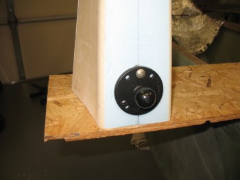
 And here’s the Melvill screws installed. Not bad looking at all!
And from the inside . . .
And then the base of the headrest . . .
And all together!
Here’s a shot of the finally cured & cleaned up seat back & spacer piece.
Also, a shot of the lower seat back, also cured & cleaned up.
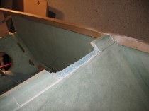
And now for this evening’s finale . . . mock-ups! I started by placing the seatback shelf in its position on top of the current seat (whose straightness was significantly enhanced by the post cure).
 I then added the headrest.
 And a shot of the lower seat back in its approximate position. Ironically, I will most likely have to notch this piece as well on both sides for it to fit under the longerons.
I thought I would also show a few pics of the rectangular rollover cross bar with the the roll bar in its approximate position.
A head-on shot. Of course the cross bar will sit further aft, about where the expander is currently positioned.
And the final shot of the evening focusing on the rectangular rollover cross bar & the headrest sitting on the seat back base.
•••
20 March 2015 — I would love to say that I got some really cool layups in today, but I can’t. Today was all about prep. And I mean I literally spent about 10 hours prepping a myriad of nitnoy things to get chapter 8 knocked out.
I started by spending about a 1/2 hour sanding the face of the seat back shelf so that it was as straight & level as possible. Sometimes I feel more like a sculptor more than an airplane builder! Once it was level, and I had it in the fuselage, I just wasn’t sold on the sharp edge that would make up the corner of the back of the seat and the new seat back shelf (headrest base) that I was working on. I decided that I was going to radius that corner with a 3/16″ round-over router bit.
I clamped the piece to the work bench, and due to the edge being so sharp & the angle so great, I had to use a guide to keep the bit at the right position on the cut.
Here’s a shot of the aft side 3/16″ router cut on this piece.
I then radiused the front edge 1/8″.
I mocked it up to check out the look of the radiused edges, and was happy with the results.
After I checked the seat back piece, I then radiused the top edge of the lower seat back piece using the same 1/8″ bit I used on the front of the piece above.
Here it is after I routered the edge.
I then added that piece into the mock-up.
I turned my sites on getting the aft hard points for the headrest prepped so it’s ready to glass either later this evening, or tomorrow. I measured out and marked the positions of the 2 aft headrest bolt holes.
I then drilled the holes.
Next, I started making the hardpoints that will sit opposite these aft bolt holes in the headrest. These hardpoints will be mounted in the foam that makes up the seat back shelf, much in the way that the original Long-EZs had their seat belt hardpoints configured.
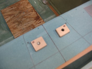
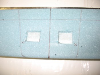
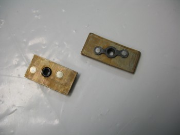
I started by grabbing some 1/4″ Birch Plywood to use as my hardpoints. I’ll also be using the K1000-3 nutplates. I marked up the first hardpoint using the K1000-3 as the determinant for my dimensions.
After I drilled the center hole large enough that the stem of the K1000-3 nutplate would fit inside, I traced the nutplate and used my razor knife to make a pocket for the nutplate to fit in so it will sit flush as its embedded inside the foam mounting point.
Here’s the 2 nutplate assemblies that I’ll embed so that they become the aft hardpoints for the headrest assembly to bolt to.
And the reverse sides. BTW, I intentionally made these slightly different sizes in order to tell them apart and not get them confused during the installation.
I set the headrest’s aft hardpoints aside and made up 4 dowel guide pins to help the new seat top with the existing seat, especially as it’s curing.
Here’s a picture of them installed in the new seat top piece.
With the seat top ready to go, there was still something I needed to complete before the seat top gets glassed in permanently. The roll bar will be bolted in from the inside of the longeron out using 1/4″ bolts at the very front of the side roll bar longeron rails, and at the aft end of the rails. In the middle area, where the new composite seat assemble will be built, I won’t have access to install a bolt there, since the entire area will be encased with the seat back assembly. So the third, and middle hard point for the roll bar will be a 3/16″ screw that will be installed from the top to the bottom of the longeron. Since the longeron isn’t that wide, I will be using a 3/16″ screw to ensure a lot of strength, but also minimize the cross section of the hardware installed in the longeron.
Again, since I won’t have access to that area, I can’t secure the screws with the traditional nuts & washers. For this endeavor, I’ll again use a K1000-3 nutplate. However, instead of mounting it into wood, I’ll be riveting the nutplates to 1/8″ 2024 aluminum backing plates.
Here’s the nearly finished set.
And from the other side.
Tomorrow I’ll shape the edges & then Alodine the aluminum before riveting the nutplates to the pieces.
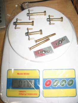
I also spent a decent amount of time figuring out my hardware requirements for the rollbar assembly. I was curious about the weight of the hardware, so I threw them all on the scale: 0.17 of a pound. Not bad!
With that out of the way, I started mocking up the headrest on the seat back shelf so I could determine exactly where the headrest hardpoints needed to go.
I measured, eyeballed, laser-sited, and double-checked the hardpoint positions before pulling the trigger on marking them up.
Here’s a shot of the headrest hardpoint positions prepped on the seat back shelf.
•••
21 March 2015 — I started with a list of about 10 things to get done today. Well, I finished 2 of them! Between getting a late start and going out to dinner with friends this evening, I was merely able to get the lower seat back glassed.
I prepped the 1/4″ thick x 1-3/8″ yellow foam addition by adding a couple of extensions covered with duct tape to the outer edge of the yellow foam piece. The reason for these extensions is that when they’re removed after the glass cures there will be about a 1/4″ glass overhang for the connecting foam piece that will be glassed in from the top side seat back assembly. In short, this glass overhang will be the meeting point between the lower seat back assembly and the upper seat back assembly.
I then scurried up a piece of BID for the layup.
And some for the BID tape that I’ll be laying up in the corner to add strength.
I micro’d up the foam and added a fillet in the corner.
I laid up the large ply of BID first, then laid up the corner tape. Once that was all finished I peel plied the lower edge and the corner tape.
A few hours later I razor cut the piece, pulled the peel ply and cleaned it all up.
Below shows the 1/4″ piece I added to the lower seat back piece, and the glass overhang on the aft side of the yellow foam.
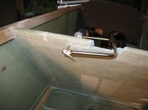
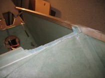
Of course I mocked up the newly glassed piece along with the other seat back components. Below you can finally see the notch for the roll bar’s rectangular cross bar.
I added the cross bar so I could see how it all looks together.
Here’s a shot from from just a tad bit forward so you all can see the front edge of the cross bar aligned with the front edge of the lower seat back. Looks like the fit should be pretty darn good.
And here’s the final mock-up shot of evening.
•••
22 March 2015 — Today I started out by laying up some reinforcement BID on the longerons, which will lie directly inside the roll bar side rails. I wanted to add some reinforcement to buttress up the longerons to give the roll bar bolts just a little more to grab a hold to.
Now, to back track just a bit. I was planning on glassing in a nutplate riveted to a piece of 1/8″ 2024 aluminum (see pic below) under each longeron to allow me to install a countersunk screw in the center-“ish” position on each of the side rails as one of three attach screws/bolts on each side of the roll bar. However, as I was cleaning up the underside of each longeron to ready the floxing/glassing in of these nut plate assemblies, I realized that the original flox fillet in the corner between the fuselage side wall and the underside of the the longeron was keeping the aluminum plate from sitting level. After messing around with it for a bit, it was clear that the nutplate assemblies would only sit slanted with the underside of the longerons in their current state, no matter how clean the undersides of the longerons were.
I also realized & had accounted for the fact that positioning the roll bar side rail middle mounting hole was going to be a bit difficult to align with the longeron hole/nutplate assembly since the side rail would have to be drilled at a later point, while the longeron would have to be drilled prior to mounting the nutplate assemblies to ensure they were aligned correctly with the mounting screw hole. Of course it’s always easier to get all the associated components together, ensure all is aligned and then drill it all in one shot. This method is definitely what I preferred to do.
So I went with Plan B, which involved a 2-step process for the center side rail mounting screw. First, I would glass in a small 1/16″ thick phenolic shim, 0.35″ in width (half of the longeron’s 0.7 width). The phenolic gets glassed in on the interior underside of each longeron at the point the nutplate insert will get installed, with the inboard edge of the phenolic shim even with interior edge of the longeron. The resulting gap behind the phenolic shim then gets filled in with thick flox, and voila, a straight bottom surface is created on the longeron to mount the nutplate assembly AFTER the side rail is in place, and both the side rail and longeron can have the middle screw mounting hole drilled simultaneously. Once the side rail and longeron are drilled, I’ll install the mounting screw from the top to secure the nutplate assembly on the underside of the longeron, at which point I’ll flox & glass the nutplate assembly in permanently.
So to start, I pre-pregged 2 plies of BID.
Here’s one of the phenolic shims. The pic’s not the greatest, but you can see a little bit of the quick sanding I did to rough up the surface a little for better bonding to the epoxy.
And here are the side rails reinforcement layups.
Ok, now that I wrote the novella above to tell the story for two mere simple layups of 2 plies of BID on each longeron, I will regale you with yet another tale. The minor issue that I wanted to resolve was that I wanted access to the interior side of the seat back top assembly. Primarily for two reasons:
1. Construction of the seat back assembly
2. Storage
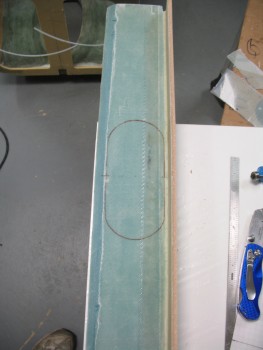
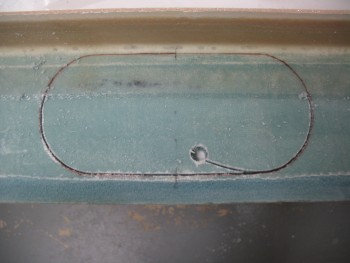
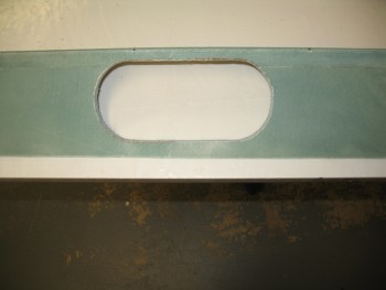
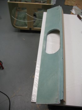
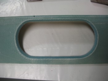
I’ve been bantering this around in my mind for the past few days, and was thinking about cutting out a rectangular hatch on the lower back support, and possibly hinge it and secure it with some type of latch. Well, I had an epiphany and decided to not only hold true to K.I.S.S. but save a little weight and go traditional in keeping with Burt’s style. Thus, I would simply cut an oval shaped hole, radius the edges and call it a day! This gives me the access I want, saves a little bit of weight, and looks kind of cool (I think!).
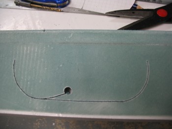
I grabbed a piece of scrap wood and threw some duct tape together to create a seat back hole mock-up.
After I traced out the tape & before I cut out the oval test access hole, I thought I should start smaller and work my way out. I drew another hole outline about 1/4″ inside the first one and used this as my cut line.
Then I tested the available access space. Since I could actually move my hand in & around very freely, I narrowed the height of the hole by another 0.2″ and shaved about the same off the width.
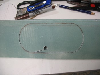
I took my finalized dimensions upstairs and created a template on graph paper, cut it out and had my new access hole outline template ready to go.
Back in the shop, with the lower seat back piece in hand I knocked out some clean-up tasks first by trimming the rear glass overhang–at the aft side of the 1/4″ yellow foam–down to 1/4″ to match the strip of yellow foam that will connect the upper seat back shelf assembly to this assembly. I also sanded it down for a good gripping edge since I had forgotten to peel ply this edge (yeah, what gives?? I love peel ply!)
Then I used my newly made template and traced around it on the INSIDE of the seat back, since that was where all my clearance issues had to be accounted for.
I drilled a starter hole & then used my jig saw to cut as much as I could on the back side of the lower seat back assembly before my blade guard hit the yellow foam piece.
[Note: You may notice some air bubbles in the micro fillet at the corner of the blue and yellow foam. I’m fairly certain that this was caused by my having to re-position the yellow foam a number of times to get it to line up 90° to the blue foam. I would stipple the air out with a brush, have to tweak the position of the of yellow foam (since I wasn’t using a jig) and then the bubbles would reappear. I was more concerned about angular positioning than the bubbles, since I’ll simply inject those later].
I then flipped it over, tweaked the outline to ensure it was straight and finished cutting out the hole.
After the hole was cut, I sanded down the edges and verified the glass edge on the BACK edge of the hole was straight (since that’s the edge the router bit roller will be using as its guide).
Then I took this puppy out back, clamped it to a sawhorse and routered a 1/4″ radius on the access hole’s edge. I was going to try to go with the same style as the CS spar oval access hole as far as the hole’s edge, but I simply didn’t have enough clearance to work with. So, except for the straight bottom edge of the oval, I’ll cut a wedge out of the foam on the back edge and create an internal flox edge to strengthen the glass at the hole’s edge.
Sorry for the crappy pics below, but they show the cured 2-ply longeron layups that will add a base & some strength for the rollbar side rails. I specifically DIDN’T add glass to the tops of the longerons simply to avoid adding height to the side rails in order to minimize clearance issues with the canopy frame.
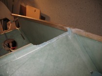
And here’s a shot with the lower seat back piece with the newly cut access hole thrown place in for a quick mock-up.
And a head on shot of the same.
•••
23 March 2015 — After days of seemingly micro steps (pardon the pun), I finally feel like I got some heavy lifting done on the seat back assembly. I could have actually done this layup last night, but it was too late and I was too tired. So this morning I was able to jump right in and get started.
My first order of business was scrounging for BID for the seat back shelf to existing seat back layup. The plan is to use a 4″ wide 2-ply BID layup under the front part of the seat back shelf since that’s all the support glass that the front of the seat top will get. The aft side of the seat will only get 1-ply of 2″ wide BID since I’ll be adding 2 more plies of BID on top of the rear BID tape in the final layup of the seat back shelf.
Below is the 4″ wide 2-ply BID that I wetted out for attaching the front & underside of the seat back shelf to the existing seat back. Since this is the only layup going in here, I won’t be peel plying it.
I slathered up the foam on the seat back shelf assembly with micro. I then filled the spike holes with flox.
And then did the same on the foam for the existing seat back.
I laid up the 4″ wide 2 ply BID tape on the front side to attach the 2 seat parts. The top side was overlapped with about 1-1/2″ of the 4″ inches, while the bottom existing seat back get the rest of the BID tape (about 2-1/2″).
I then wet out the 2″ wide 1-ply BID in a pre-preg setup for the layup on the aft side of the seat.
Although hard to see, below shows the seat front side layup. I peel plied just the bottom edge with 1″ peel ply tape to keep the edge transition smooth and fiberglass barb free!
And here’s the aft seat layup. Since there will be more BID added to the aft side of the seat, I peel plied this layup.
To keep the top edge of the front part of the shelf straight, I pressed the rollover cross bar into service and taped the edge to this rectangular metal piece.
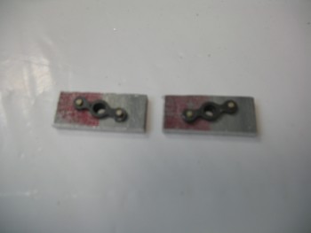
While the seat back was curing, I Alodined the 2 small 1/8″ thick 2024 aluminum plates that I used to house the nutplates after I riveted them into the aluminum pieces.
Here’s a closeup of the nutplate assemblies that will be used to secure the middle screw on the roll bar assembly side rails.
 You’ll note that one nutplate assembly is shorter than the other. That’s because I was trying to shape these assemblies in order to make them fit under the longerons before I realized that I needed to go another route (aka “Plan B”).
I started prepping for the next couple of layups by cutting the glass & plastic for the pre-preg setups for the BID required to cover the nutplate assemblies on the seat back shelf, and the 2″ wide 1-ply BID tape that I’ll use to glass the 1″ foam strip under the front lip of the seat back shelf. Finally, I had to actually pull some BID off the roll and use my glass cutting table to get the 2 pieces required for the seat back shelf top layup (the rolled up glass below).
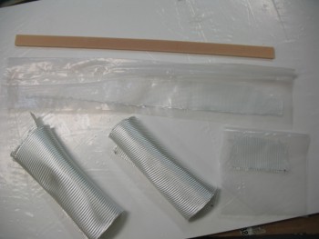
I used thin screws and fast hardener to attach the 1″ yellow foam piece to the front lip of the seat back shelf. The yellow foam piece will be the back “wall” of the notch in the seat back assembly that the 4130 steel roll over crossbar will be resting in. The 2″ wide 1-ply BID tape was laid up on the aft side of this yellow foam piece and with the bottom side of the adjoining seat back shelf.
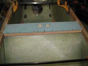
Here’s a quick shot of the peel plied pulled from the aft seat layup, and then a fairly robust sanding I gave it to smooth out some of the rough edges between the 2 seat pieces.
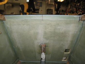
Being a cheapskate, the flox from the first layup was still good so I used it to mount the nutplate assemblies into the top of the seat back shelf and also to fill the holes leftover from the screws I had just removed.
By using the fast hardener and setting heat on the 1″ foam lip layup, it cured in no time flat.
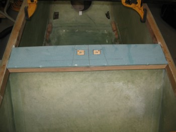
I started the layup on the top side of the seat back shelf by working the pre-preg for the BID inserts that go over top of the wood nutplate assemblies. Of course these make up the rear bolt hardpoints for the headrest.
After I got the 12-plies of BID situated as neatly as possible in each of the nutplate cutouts, I micro’d all the foam faces to prep for the upcoming 2-ply BID layup (shown below after I peel plied it).
Here’s the main layup shown from the aft view. Also peel plied.
 I bought some heat laps quite a while ago in preparation for building my fuel tanks, so I decided to see how they work here & see if they’ll give the layup a boost in its cure time!
•••
24 March 2015 — This morning I started by carefully drilling the holes in the nutplate inserts I embedded into the seat back shelf that will serve as the rear bolt hardpoints for the headrest. It took about 10 good minutes to dig out the saran wrap I stuffed into the nutplate on one, and about 5 on the other. No surprise… nothing is predictable when building an airplane.
I had a couple shots that I took quickly but didn’t realize how jacked up they were until I downloaded them. Just pics of the hardpoints and the initial (official!) mounting of the headrest to the seat back assembly.
I then went on a beautiful flight for almost 2 hours. I of course didn’t get to see hardly anything because I was wearing foggles the whole time… But, I did get to a watch a C-17 on final pass about a 1000 feet below us as we traversed Quantico’s Class D airspace.
Ok, back to the build. I cut a 2×4 into the size of the 4130 crossbar to use as a substitute for sizing, fit & checking out other components on the rollover assembly. Below gives you a general idea of what the base will look like with the headrest and the crossbar in place.
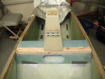
I measured, mocked up and trial fitted the rollbar a number of times to get the correct angle and initial dimensions figured out. Since my rollbar will be slanted aft, figuring out the cut angle was a little tricky (at least for me…).
The lean angle on my roll bar is 69° so I cut the end of a piece of scrap wood (actually the one below holding the rollbar down) at 21° to get the correct template. I verified the angle & it was spot on.
I messed with the rollbar and contorted my mind a few times to figure out how I was going to get a straight cut across the bottom of the rollbar to make each side level with each other on a flat surface, but then add the angle in for the aft lean.
I decided to work one axis at a time. I figured out a line that if cut straight across the bottom, the rollbar could easily stand straight up with each side sitting flat on the surface. So on each side of the separate tubes I drilled a small hole along the plane of that line.
Then for the aft lean angle, I laid the roll bar flat & laid the scrap wood template piece next to it (with the 21° angle). I marked the front side of each rollbar tube with the long side of the template, then drilled a hole on the top center of the tube as it lay there on the table. Then I flipped the rollbar and did the same thing on the aft side with the short side of the template.
When I was done, I had 4 holes on each tube, 90° from each other as for as the cardinal center lines of left, right, top, and bottom of the tube, but all over the map in any semblance of an identifiable relationship. I took a Sharpie and as I started literally connecting the dots, I could see that the key to understanding the line was the cut angle and the flow around the curves of the tube. At that point I was fairly certain that I had a good cut angle for mating the rollbar to the cross bar.
I clamped the rollbar to a sawhorse & used my Dremel Tool to cut the tubing at the lines.
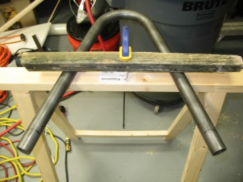
Now, I targeted the lower parts of each down tube of the rollbar to give me a lot of wiggle room to lock in the cut angle. I could envision a number of iterations required to lock in this cut. Well, that didn’t happen. I actually got it right the first time around! Which is a little annoying since IF I had known that I was going to get the cuts so good right out of the gate, I would have just marked the rollbar in the correct spot and been done cutting some fairly hefty 4130 steel!! Ha!
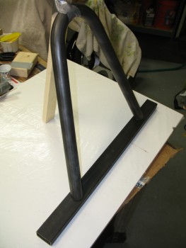
Here’s a close up shot. I’m happy that I cracked the code, but man I wish that this was correct dimensions so I could weld this puppy up!
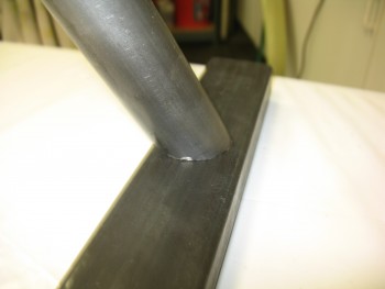
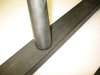
And the money shot….
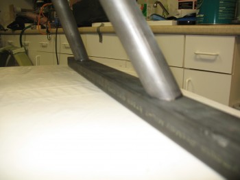
Here’s a pic showing the general feel of how this will look when it’s put together. Also, the rollbar is definitely too high and will be getting shortened another couple of inches.
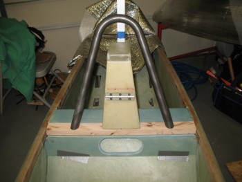
•••
25 March 2015 — I started off today by knocking out the two quick aft seat BID reinforcement layups. Just like the reinforcement layups on the forward side of the seat, the longerons just aft of the seat will get 2 plies of BID to reinforce the respective longerons for the Rollbar assembly side rails, and to give the aft 1/4″ bolt a little more meat to bite into.
I sanded down the existing glass to prep it for the layups. I then marked the aft edge of the layup with duct tape, which will of course align with the aft edge of the rollbar side rails.
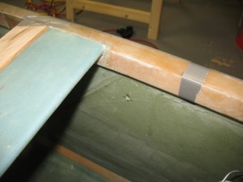
I tracked down 2 plies of BID and cut them to the approximate size needed, as well as the appropriate sized piece of plastic sheet required for the pre-preg setup.
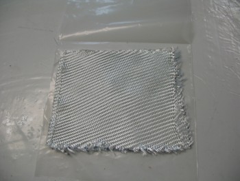
I then whipped up some MGS 285 epoxy with fast hardener and wetted out the BID in the pre-preg setup. I then marked up the plastic with Sharpies and cut out the individual pre-preg layups for both the left & right longeron.
[Note: In my haste, I marked up these pieces incorrectly since I used the measurements at the top of the longer to the seat back, and then bottom edge of the longeron to the seat back. Since these–like the front ones–don’t cover the top of the longerons, and only cover the inside edge and bottom, I mistakenly didn’t account for the bottom 0.7″ when I marked these. No big deal since it only results in a slight gap near the seat back].
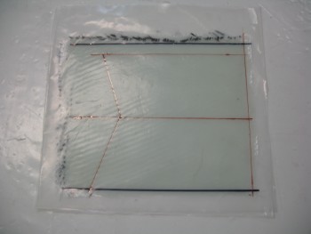
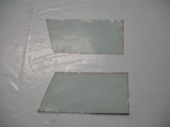
I then completed the longeron BID reinforcement layups on each side. Here they are completed, peel-plied & curing.
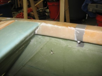
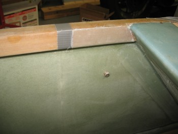
As these layups were curing I went to work on the rollbar. My first order of business was to shorten it so that it reached my approximate target height of 13″. Since the angle & fit was good on my initial cuts, I “simply” needed to replicate those cuts to shorten the rollbar.
I did this by drawing a reference line near the top center of each rollbar leg. I then wrapped green painters’ tape around the end of each tube.
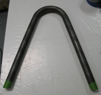
I cut the tape to match the contour of the bottom of each tube.
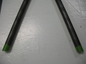
And then marked the reference line down the top center of the tape in line with the previously marked reference line.
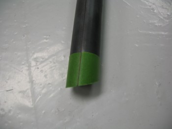
With the bottom edges of the tape contoured to the existing cut angles, and my reference lines marked, I marked the distance from the bottom edge for the new cut lines. I then simply removed the tape carefully from the bottom of each rollbar tube and moved them up to the marked cut line, while ensuring the tape was aligned with the reference line at both the top & bottom of the tape.
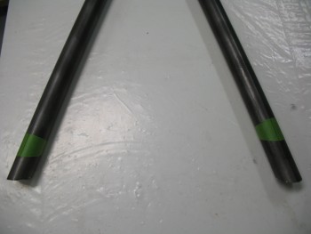
With my new cut marks set I clamped it down and using my Dremel Tool, cut the rollbar down tubes to their new lengths.
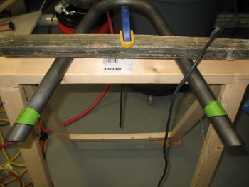
And here it is shortened to its new height.
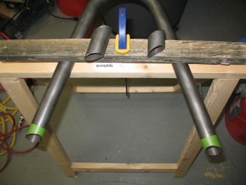
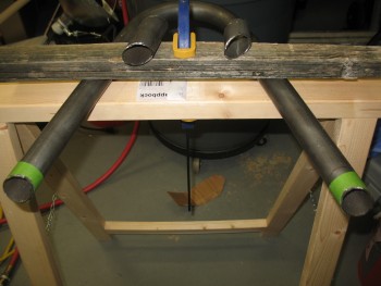
You probably noticed that one leg of the rollbar was cut shorter than the other. The reason for this is that with the inverted “V” geometry of the rollbar, I can embed one leg of the rollbar into the cross bar so that I can weld it at both the top of the cross bar and the bottom, while the other side rollbar leg only gets surface welded to the cross bar. This should allow for a stronger rollbar than if only each side gets surface welded (make no mistake, I believe that would still make for a very strong rollbar as well), and it also opens up access to the right rollbar tube on the bottom of the crossbar to run any cable(s) through the rollbar tubing if I should ever want to mount a video camera, or other device requiring a cable.
With the above in mind, I drilled a hole in my wood cross bar template ONLY on the right hand side to allow for the right rollbar leg to sit down inside the crossbar.
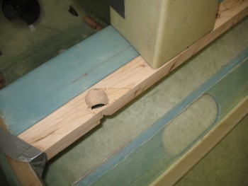
I of course had to play around with it for a bit and use a small sanding drum to contour the inside of the mounting hole, but I got it fairly close. Below is the mocked up rollbar with its new adjusted height.
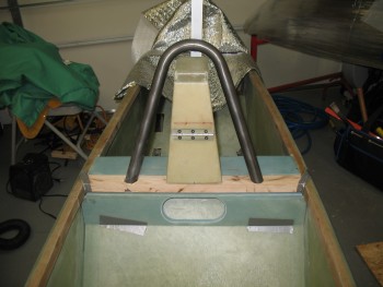
I’ll of course need to fine tune it, but I think it looks pretty good.
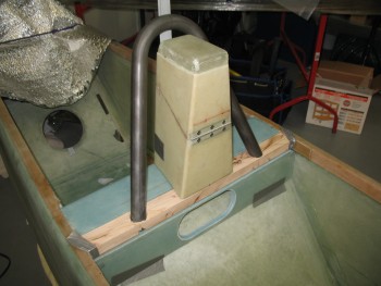
Here’s a closeup of the right rollbar leg as it sits embedded in the wood cross bar mockup.
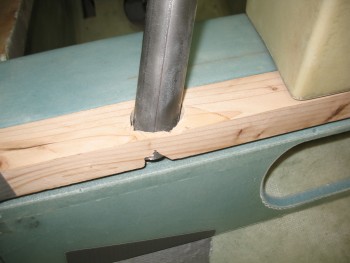
•••
27 March 2015 — This afternoon I started cutting the rollbar side rails to prep them for the extensions I’ll be welding on them.
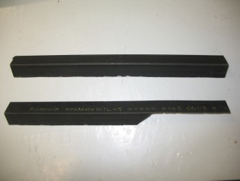
As I cut each side rail, I also cut a groove between each side of the seat back shelf edge & the adjoining longeron. It took a few iterations to get the side rail to slide in, but the fit on each side is still fairly tight. Below is a couple of shots of the right side rollbar side rail.
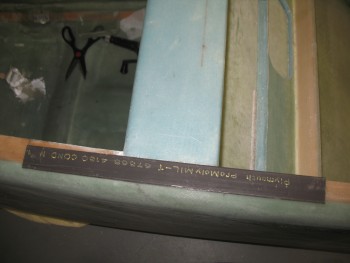
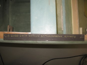
Here’s a view from the front showing each side rail cut & in place.
I then cut & added the wood cross bar mock-up with the rollbar installed.
•••
28 March 2015 — I started out today by confirming the measurements & angles of the aft seat side rail plates. These plates will get welded to the top side rail pieces and will sit just aft of the front seat & against the longerons.
To make these 1-1/2″ high plates, I needed to weld two 3/4″ wide 4130 strips together. I prepped the edges of each 4130 strip.
I could have spent a fair amount of time practicing my TIG welding, but I figured I would start in and give it a try. Having a fair amount of experience welding I knew the difference would be between good looking strong welds–with a good amount of practice–or strong welds that may not come out as sexy looking. Another issue was that the filler rod I have on hand is a little too big for this weld, so it was a bit of challenge in adding filler metal to the weld.
Here’s the resulting ugly but effective weld.
And here’s the piece after I cleaned it up.
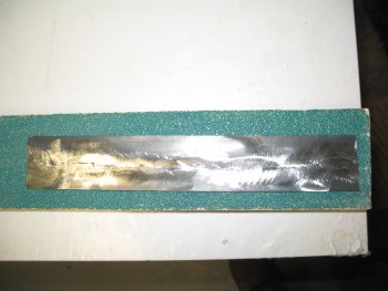
I then marked it & cut it diagonally so that the separate pieces fit in the aft seat spot.
After tweaking the aft seat side rail plates for each side, I prepped the right side top rail piece (shown in the pic above & below) so I could weld an extension tab onto it at the aft end.
As a reminder, I should note that when I originally widened my fuselage by 1.4″, I also widened all the longerons from the front seat aft, top & bottom, to bring their inside edges inboard to allow the engine mounts to fit correctly.
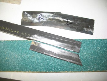
Here’s the right side rail below with the extension piece added on.
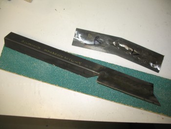
I did the same for the left side top rail, welding an extension to it as well.
•••
29 March 2015 — I started today by making a template for the outboard edge of each side rail. I simply used a piece of tracing paper on each side and traced the outer edge just inboard of the longeron (one of the cool things about MGS is that it cures CLEAR).
I taped the tracing paper on each end and then drew the outline with a pencil.
Below are the side rail outboard edge outlines for each side.
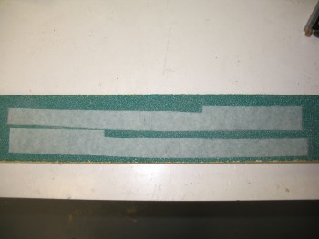
I taped the paper templates to their respective side rails & marked the outline.
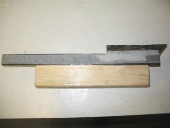
Then I prepped the right side rail first to cut.
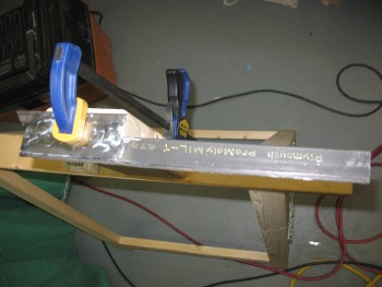
Below is the right side rail installed after I trimmed the outboard edge to match the profile of the longeron below it. I also hacked off the aft triangular jut-out, a leftover from the extension I added to the side rail yesterday. You can see how the extension now more than covers the entire width of the longeron aft of the seat (it gets trimmed below).
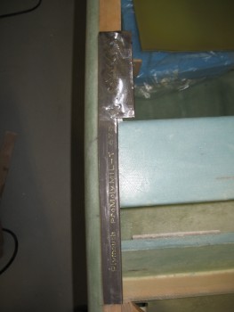
And then I did the same with the left side rail.
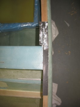
Here’s a quick shot showing the progress of the side rails up to this point.
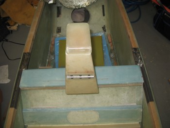
Next, I fitted the right side rail’s inboard side-longeron piece (that I made yesterday) and marked up the intersecting line on the top side rail piece extension (that I also added yesterday). I transferred the cut line on the bottom side of the side rail extension to the top & then cut it. I then did the same for the left side.
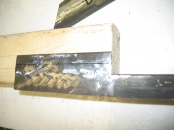
Here’s the left side showing the top side rail extension piece cut & matched to the inboard side-longeron piece.
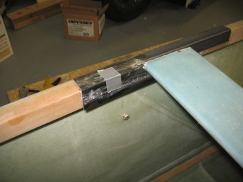
I then prepped the right side rail extension piece to weld to the longeron side-piece.
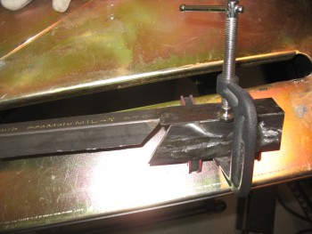
Right longeron side-piece tack welded.
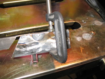
Right side rail.
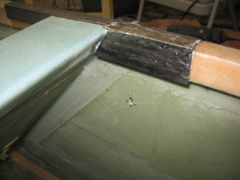
Left side rail prepped for welding.
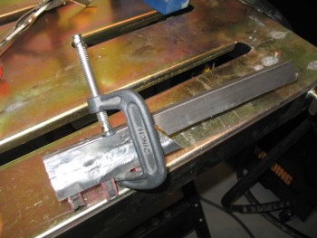
Left side rail tack welded.
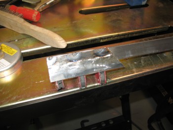
Left side rail welded.
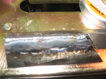
Left side rail.
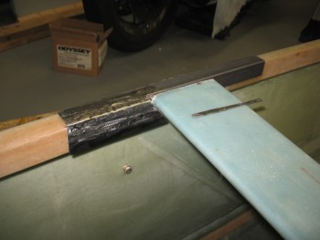
Right side rail front extension piece.
I’ll be adding a 4″ reinforcement plate to the front side of the side rail. To keep any potential corrosion at bay, I sprayed the metal that I’ll be welding this plate to with weldable primer.
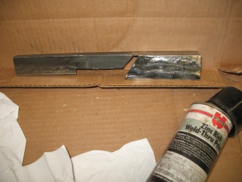 Here are both side rails prepped with weldable primer in the area that will receive the forward reinforcement plate.
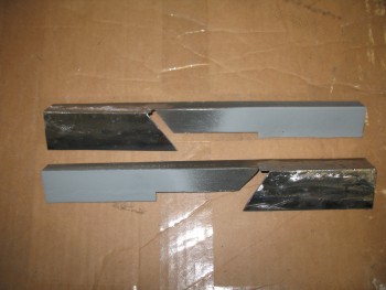
Speaking of the front reinforcement plate, here are the three 3/4″ x 4″ strips that I’ll weld to make up these 2 plates.
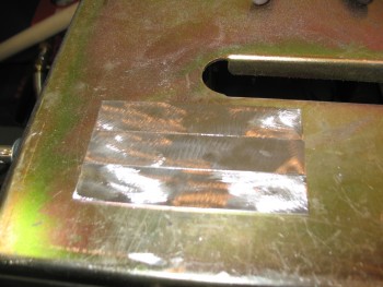
Once welded, I’ll cut the new plate down the center to create 2 plates 4″ long by about 1-1/8″ wide.
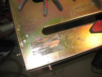
•••
30 March 2015 — Awright, today was all about the side rails. It appears that these are becoming the long pole in the tent for welding up the rollbar assembly.
I started out by shooting the forward side rail reinforcement plate (still to be cut in half) with weldable primer.
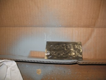
As the weldable primer cured, I marked up the bottom edge of each side rail plate that covers the inboard longeron. These plates are just a tad long, so I trimmed then up to reduce weight and to ensure the GIB doesn’t get snagged by overhanging metal.
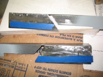
I trimmed up the right side rail to allow a better install of this removable rollbar assembly. With the rounded edge, it creates a better angle when installing the rollbar.
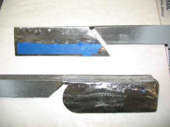
Here is the left side rail also trimmed up.
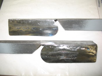
I then cleaned out the longeron notch on each side to create a channel immediately behind the seat back where it meets the longeron.
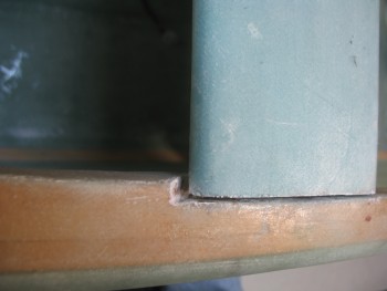
Here’s a shot of the side rail, with the welded-in connection piece that ties in the aft side rail to the front side rail. As you can see, it’s the little piece that makes up the notch that allows the side rail to expand out for the thicker aft longeron. I will say, that up to this point that this was the most difficult welding endeavor I’ve undertaken thus far on this project.
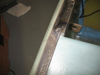
Here’s a closer view of the inserted metal piece that connects the different widths of the side rails.
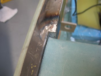
Here’s the cured plate that will be cut in half that will make up the reinforcement plates on each side rail at the furthest forward point of the side rail.
Here’s a shot of the side rails installed.
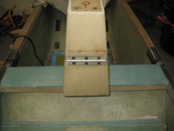
And a shot of the left side rail.
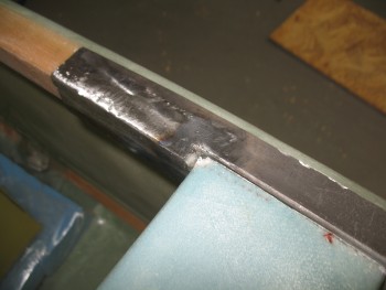
Here’s the final shot of the evening, which is the prep for welding the reinforcement plate to the right side rail.
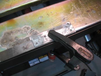
•••
31 March 2015 — I finished welding the right-side reinforcement piece last night. I started off today by trimming the aft seat rounded piece so that it didn’t protrude forward of the very aft corner of the seat back if you drew an imaginary line straight down. This is required with the new reinforcement plate welded into place at the front of the side rail since the side rail in effect “straddles” the 4″ seat back shelf.
Since the rollbar cross bar will get welded into place onto the reinforcement plate and sit just forward of the seat back shelf, the aft line of the reinforcement plate will essentially be the aft side of the cross bar. Thus, as long as I can install the side rails now with the front reinforcement plates welded into place, it should take only some very minor trimming, if any, to install the side rails with the cross bar welded into place.
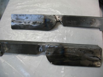
With the final trimming completed on the right side rail, I then installed the reinforcement plate to the front side of the left side rail. As you can see, I drilled 7 total 3/16″ holes into the actual plate being added, and 6 holes situated in different distinct locations on the side rail (so that none of the holes between the 2 pieces align). This allows me to weld the sides of the holes and then fill the holes in with filler metal so that there are essentially 13 welded hard points “in the field” to attach the plates together. I then of course weld around the perimeter on all 4 sides to create an extremely strong joint between these 2 pieces of metal.
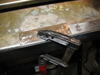
In the pic below you can see where I welded & filled the holes from the inside of the side rail: essentially going “through” the side rail, welding the edge of each hole to the reinforcement plate and then filling in the hole to create a solid surface.
Although not shown here, I ran into an issue when welding the edges of the reinforcement plate to the side rail where I wasn’t getting a good arch between the tungsten tip & the metal, it especially being difficult to get a good weld bead going. Also, a ton of spatter. I thought it was the Tungsten electrode, so after regrinding a couple more electrode tips, I tried it again. A quick note in that I’m using straight Tungsten so far, because I only have about a third of just one 1/16″ 2% Thoriated Tungsten electrode left, and I was saving it for the cross bar to side rail and roll bar to cross bar welds. This means that I already knew that the straight Tungsten didn’t weld as nicely as the Thoriated stuff (yes, I’m cheap!).
Well, I may be slow but I eventually got it! I finally figured out that I was simply out of Argon! I was kind of surprised since I didn’t figure I would use a whole tank on the roll bar assembly, let alone half of it. Thus, I will be hauling my tank down to the gas supply store today to swap it out it for a full one. I’m fairly confident that tank should last me for the rest of the roll bar build.
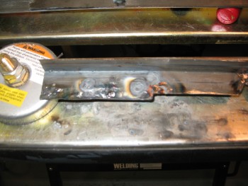
Here are the side rails in place, each trimmed so they can go on & off with the new forward reinforcement plates welded into place.
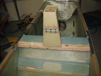
I also trimmed the sides of the mock wood cross bar so that it would fit as well.
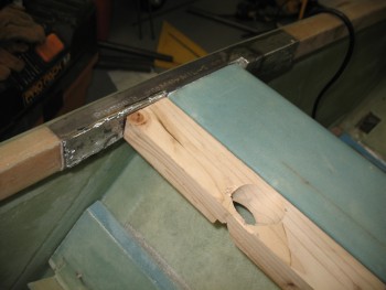
With no welding due to a lack of Argon gas, I spent the next couple of hours trimming down the left side, or leg, of the roll bar tubing. With the right side leg longer & embedded into the cross bar–so that it gets welded on both the top & bottom sides of the cross bar–I want the bottom of it to sit on the inside bottom “floor” of the cross bar. Well, currently its about an 1/8″ too high and need to sit lower in its mounting hole.
Trimming the left side roll bar leg does 2 things: it allows the roll bar to sit centered around the headrest while the right leg sits lower into its hole (as per above), and it brings the physical attach point of the left leg closer to the center of the cross bar.
This is important since my original marks for mounting the roll bar onto the cross bar have each leg of the roll bar getting mounted 4.2″ in from the side rail on each side. Currently the right side leg is locked into that 4.2″, but the left leg started at only 3.9″ away. By the time I was done trimming down the left leg, I had closed that distance to right about 4.14″ away, less than a 1/16″ of an inch.
However, since the right roll bar leg is still not as low into its mounting hole as I’d like, and since the roll bar is sitting at 13-1/2″ high vs. the approximate 13″ that I had calculated (I’m not too concerned about this height, as long as it’s a minimum of 13″ tall … also remember the stock rollover is 12.7″ high, but that sits immediately behind the pilot’s head), I’ll be trimming down the left roll bar leg again… I’d guess no more than an 1/8″ most likely.
This should provide me with the magical Troika of 1) right side roll bar leg with the correct depth into its cross bar mounting hole, 2) the roll bar height between 13″ and 13-1/2″, and 3) the left side roll bar leg positioned 4.2″ from the side rail, as is the right side leg.
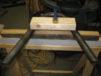
Another thing that I’m very pleased with is that when I rework a component of this roll bar assembly, whether trimming or welding it, I’ll often weigh it & update a quick weight break out chart I have on a white board in the shop. So far, it looks real promising that this roll bar assembly will have a final weight of no more than 6.25 lbs! That includes the hardware to mount it. Add that to the headrest assembly (with mounting hardware) weight of 1.3 lbs, and the total headrest + roll bar assembly weight will come in well under 8 lbs. Not too shabby IMO… I’ll take it!
•••
1 April 2015 — Ok, so today I was still trudging through some small stuff in prep for the big welds… the cross bar to the side rails, and then of course the roll bar to the cross bar.
But first, I needed some more gas!
Argon that is.
I pulled the old empty tank and ran to the welding gas shop.
And $70 later walked out with a full tank, which I promptly ran home and installed.
I did a couple of repair welds on the left side rail where I had thrashed the edge while welding on the reinforcement plate.
While the left side rail was cooling, I decided now would be a good time to drill the middle mounting holes–that go from the top down through the longerons–and flox/glass the nutplate assemblies into place on the underside of their respective longerons. I put spreader clamps in place both at the front & aft of the side rails to replicate the clamping force of the front & aft 1/4″ mounting bolts.
 I had already carried my drill marks out to the edge of the longeron, so it was just a matter of finding the near center of mass (the holes favored slightly inboard in line with the nut plates). I drilled a small pilot hole first.
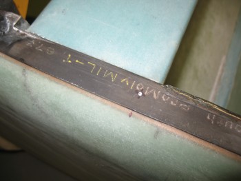
I then tested the nutplate hole alignment on the underside of the longeron in relationship with the drill bit & redirected fire on the next sized bit up (still not using the 3/16″ bit yet). I had to angle the drill just slightly outboard than the first hole I drilled using the small bit.
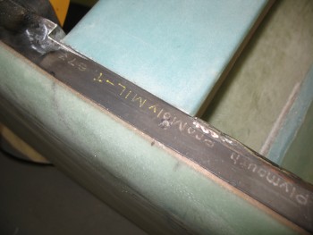 With the second hole drilled, I just need one more slight correction when I drilled the final 3/16″ hole. Although I thought I had nailed it, I did have to trim just a scant couple thou off the outboard edge of the nutplate assembly for it to line up spot on. Also, it helped that I radiused the top outboard edge to better snug into the corner.
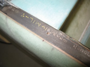
Although countersunk 3/16″ (AN3-) screws will be used in the final middle mounting hole when the rollbar gets installed, I substituted an AN3 bolt for mounting the nutplate assembly. As I’m sure you know, AN style screws can be a PITA to screw in & out, especially if just using them temporarily. Thus I went the bolt route here.
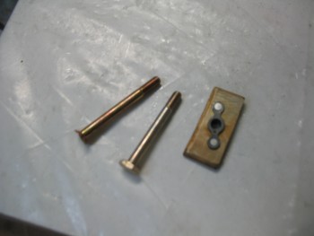 I then test fitted the nutplate assembly for the right side rail mid-mounting hole.
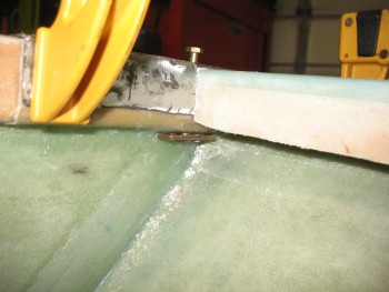
I grabbed a small piece of scrap BID to use to cover the nutplate assembly.
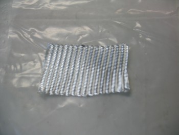
I then made a very small batch of epoxy with fast hardener, wet out the BID in a pre-preg setup and whipped up some flox.
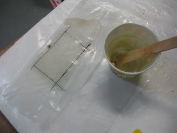
I then floxed the nutplate assembly into place, added some flox fillets all around & covered it with 1 ply of BID.
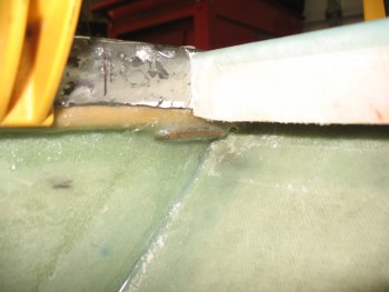
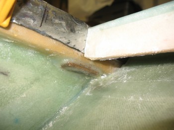
And then repeated the same thing on the left side rail.
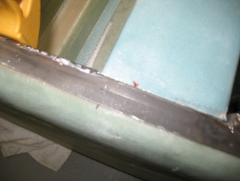
Here’s final shot of the floxed & glassed left side rail nutplate assembly for the middle mounting point. You can see why I wanted to get these mounted prior to having the cross bar welded up & in the way, or worse yet, waiting until everything was assembled and trying to get up there into that corner through the seat front access hole . . . which just would not really be possible with the amount space allowed.
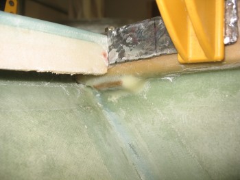
I set the heater up on the curing nutplate assemblies, and drug my rectangular 4130 steel tubing for the cross bar out to my back patio. I pulled my small chop saw out of the shed and set it up. I always keep a steel cutting blade on this saw, so I quickly checked that it was square & clamped the roll bar piece to the saw.
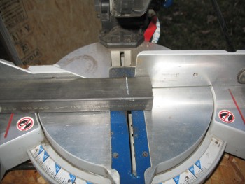
And she cut through it like buttah!
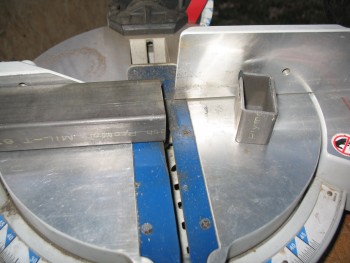
To help dial in my rear roll bar support strut/tube, I cut it at close to 55° as I could get. As you can see, I added a shim in there to get past the standard 45° that this saw maxes out at.
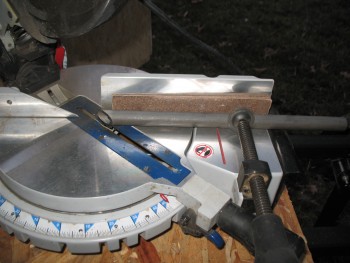
As I was taking all the pieces parts back into the garage, my best bud Greg stopped by for a visit. I haven’t seen him in a couple of months, thus I essentially took the rest of the night off. As I was showing him what I was up to on the build, I threw the mock-up below together, so I grabbed a shot of it after he had left as I was closing up shop.
You can see the cut cross bar wedged in place in front of the mock wood cross bar.
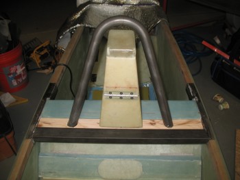
•••
2 April 2015 — Today I was only able to countersink the screws in the center mount position of the side rails. Here’s the right side rail countersunk screw.
And the Left side.
 I had to head up to Baltimore to study for & attend my Instrument Ground school, so that’s all I was able to get done today.
•••
3 April 2015 — I started today by taping up the side rails so that only the area that will lie under the ends of the cross bar was exposed.
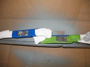
I then shot each side rail with weldable primer.
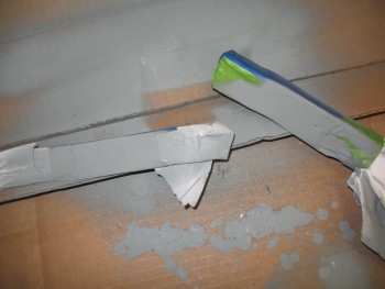
I then removed the tape after I had pulled out my chop saw from the back shed & prepped one of the 7/16″ stainless steel bars (that will be used for the aileron weight) to cut 2 pieces 7/8″ long.
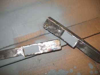
Here are the two 7/8″ long pieces of the 7/16″ diameter stainless steel cut to be inserted into the crossbar as support inserts for the seat belt mounts. I’ll drill 1/4″ holes through the center of these inserts & weld them into place in the crossbar.
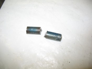
Here are the side rails re-inserted after the weldable primer had cured.
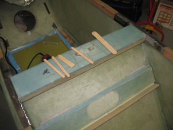
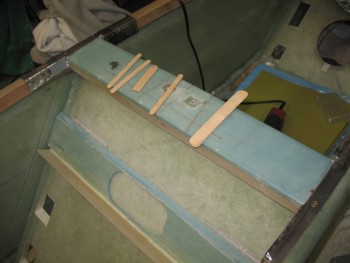
With the side rails completed, it was time to fit the crossbar into place. I marked the cross bar & trimmed each side a very little at a time.
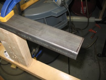
Here I’m trimming the left side of the cross bar.
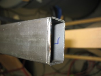 Here’s the cross bar trimmed & inserted into place.
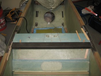
I then mounted the headrest (lower half) back into place with the aft bolts.
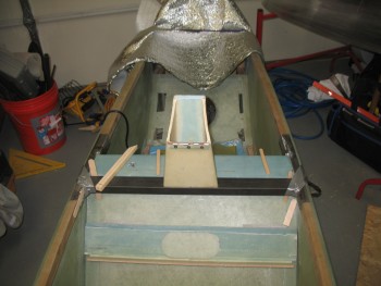 Here’s a side view of the remounted headrest.
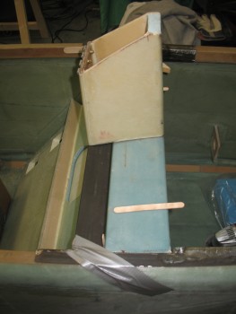
I then opened up an extra long 1/8″ drill bit I picked up specifically to drill the front mounting holes for the headrest, that will attach it to the cross bar.
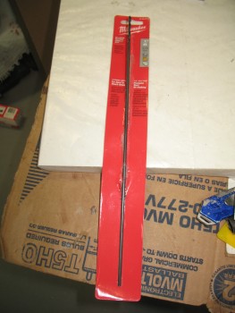
Here’s the drill bit ready to go!
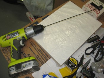
I marked the target drill points for the front headrest mounting holes.
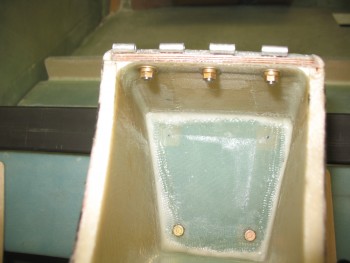
And then used the extra long 1/8″ bit to drill the front headrest mounting holes.
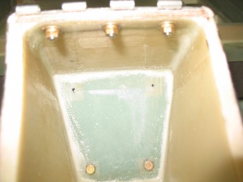
Once I had drilled both mounting holes, and confirmed that I had drilled into the cross bar, I removed the headrest.
I then drilled out the initial 1/8″ holes to 3/16″, and test fitted the holes with a couple of AN3 bolts.
I then turned my sights on the cross bar.
I drilled the 2 spots I had marked by drilling my initial headrest mount holes with the 1/8″ long bit.
And repeated the process a couple times with thicker drill bits, ending up with 1/4″ holes.
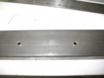
I then clamped a K1000-3 nutplate to the surface, and drilled out the first rivet hole.
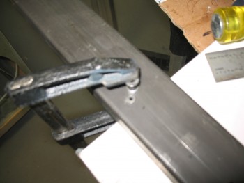
I then inserted a rivet on the just-drilled side, re-clamped the nutplate & drilled the other rivet hole.
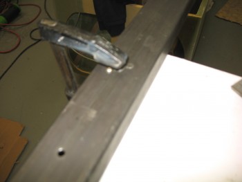
With the right side holes drilled for the headrest mounting hole, I repeated the process for the left side.
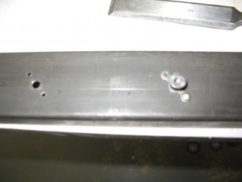 Resulting in 2 set of holes for the headrest mount nutplates in the cross bar.
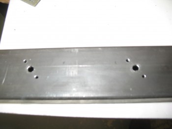
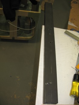
I had originally considered using flush mounted rivets but it would have been too difficult, so I simply used Cherry Pop rivets to hold the nutplates in place.
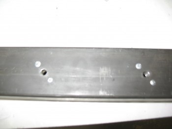
And tested the nutplates by quickly installing a couple of AN3 bolts.
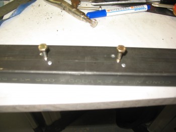
I then mounted the headrest to the cross bar, or I guess at this point in time I actually mounted the crossbar to the headrest.
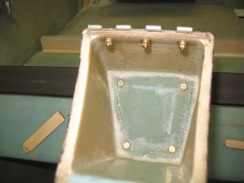
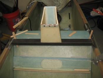 I placed the top of the headrest back in place and the lower seat back in place as well to get an idea of how the seat back, headrest & rollbar looked up to this point.
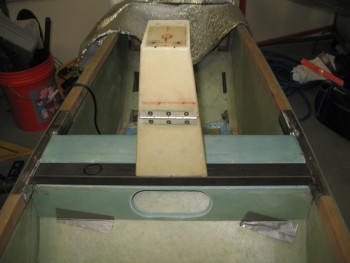 With everything looking good, it was time to focus on the seatbelt mounts. But before I moved forward with mounting the seat belt reinforcement inserts, I wanted to verify the positioning of the upper seat belt mounts.
I grabbed the wood mock cross bar & screwed the upper seatbelts to my initial, proposed mounting locations. I climbed into the fuselage to check the fitting. All seemed good at first, but after moving my head around & moved around as if I were leaning to each side to look out of the canopy, the inside edges of the seatbelts were scraping the side of my neck. Not bad, but I decided to move the seatbelt mounting points outboard a mere 0.150″, so I remounted the seatbelts & it seemed to do the trick. Clearly if I move drastically to one side of the fuselage, I’ll get a belt in the neck. But for normal ops, moving the seatbelt mounting locations out just a tad seems to worked. BTW, as I’m sure many of you know, the original plans positions received a few bad reviews for being too far outboard & not fitting so well on the pilot’s shoulders.
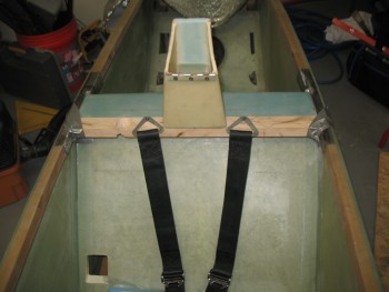 With my new seatbelt mounting positions in hand, I started drilling the cross bar for the seatbelt mount reinforcement inserts [7/16″ SS bar drilled with a 1/4″ hole].
 I got the holes drilled: 3/8″ on top to provide a positive stop for the seat belt bolt & 7/16″ on the bottom to allow for the installation of the reinforcement inserts. I then test fitted the left side seatbelt mount reinforcement insert.
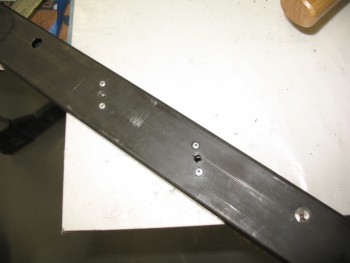 The cross bar from the bottom with one of the seatbelt reinforcement insert in place.
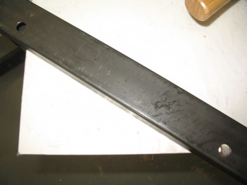 And then tested the fitting & look of the 1/4″ seatbolt mounting bolts with their associated washers.
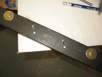
So I clearly busted my March deadline to finish Chapter 8, but I’m very pleased with the progress so far. I estimate that it should only take a few more days to finish the rollover assembly.
•••
4 April 2015 — This morning I started working on the stainless steel seat belt reinforcement inserts that will go into the cross bar at each seat belt attach point.
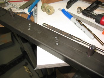
First task on the list was to drill out the core of the stainless steel seat belt reinforcement insert that will go into the cross bar at each seat belt attach point. I needed a 1/4″ hole down the center of each insert to mount the seat belt bolt from the top of the cross bar, through the reinforcement insert, with the nut being on the bottom of the cross bar.
Although I went slow & was patient, both in drill speed & pressure, I realized that my set of gold oxide drills bits just weren’t going to do the job on these stainless steel inserts. About 8 of them sacrificed themselves for this endeavor, and the outlook wasn’t look pretty for the rest of any drill bit I had, including a cobalt bit that I also kluged.
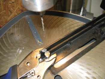
I ran down to Lowe’s & Home Depot to do a recon of possible drill bit solutions, and found a DeWalt cobalt set at Lowe’s. I grabbed that and a few extra small Titanium bits since they were much cheaper and came in packs of 2 each.
While also at Lowe’s, out of curiosity I checked their stock of metal. It got me thinking that I may go pedestrian here & instead of fighting the SS inserts, I’d simply use mild steel if they had any. They only had 1/2″ round bar stock, so I filed that idea away and headed for a quick lunch & Home Depot.
At Home Depot I picked up another steel cutoff wheel for my chop saw, which got frayed by cutting all the 4130 for the roll bar components. In their “Aircraft Metal Department” I found a 7/16″ diameter steel bar & snatched that baby up. My initial thought was that I was going to use it for backup if I couldn’t get the holes in the stainless steel inserts drilled.
But back at the house, after pulling out my chop saw & replacing the cutoff disk I tried it out by cutting off 2 steel inserts off this new 7/16″ bar. Curiosity then further got the best of me in that I drilled the 1/4″ hole in the first steel insert in about 20 minutes, only using the titanium bits and a different cobalt bit that had been spared in the earlier stainless steel debacle.
With the Round-2 drilling endeavor being a much more positive experience (And laced with infinitely less expletives) I decided that since these inserts are simply for reinforcement to assist in carrying the clamping pressure of the seat belt bolts, that I would use the new steel ones instead of suffering through another long slog at drilling out the stainless steel inserts.
Here are the 2 drilled steel inserts below. All told, the entire endeavor of drilling these 1/4″ holes into the seat belt reinforcement inserts took almost 6 hours!
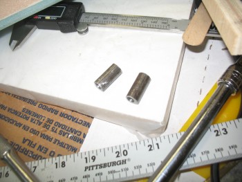
After cleaning them up, I inserted the left-side seat belt reinforcement insert into the cross bar to weld into place.
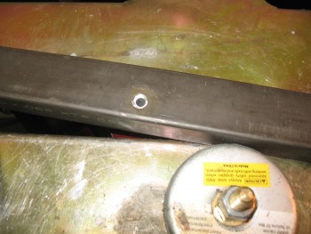
Here’s the final weld of the left side seat belt insert on the top side of the cross bar.
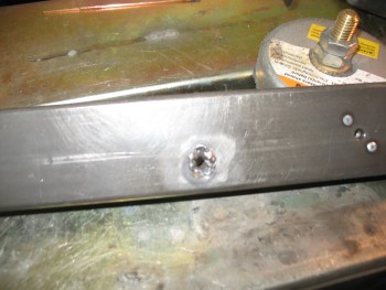
And after I cleaned it up by grinding away the protruding slag.
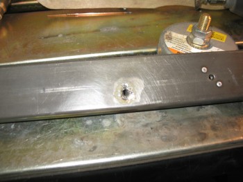
And after final cleanup & the 1/4″ hole re-drilled.
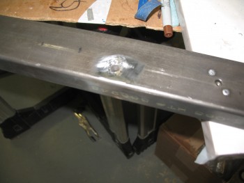
I inserted a 1/4″ AN4 bolt with an AN970-4 washer to check the fit of the bolt and ensure the proper location of the washer. I wanted the bolt as far back as possible on the cross bar, with the large washer’s aft edge aligned with the aft edge of the cross bar. This side lined up great.
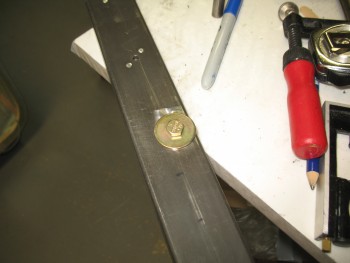
I the repeated the process for the right side seat belt reinforcement insert by welding it into place into the cross bar.
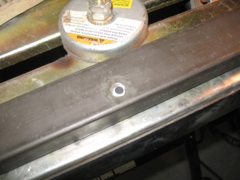
Top side weld finished. I don’t remember if I’ve mentioned this yet, but the odd-shaped circle I drew with a Sharpie (to the right of the seat belt mount hole in the pic below) is the hole for the right roll bar tube leg that I transposed from the mock wood cross bar to this one.
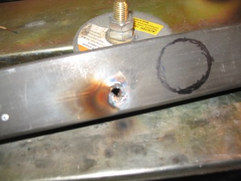
Both sides completed & cleaned up.
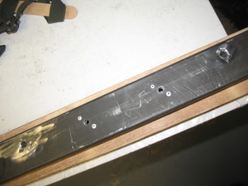
Bolt fit & locations are spot on for each side.
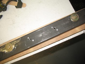
I took a couple of quick shots to show the seat belt reinforcement inserts inside the cross bar tube.
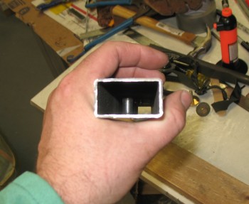
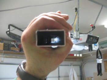
After the seat belt reinforcement inserts were welded into place, I wanted to drill the angled hole into the cross bar for the right roll bar leg. Remember, this side of the roll bar is longer and will get welded on both the top of the cross bar and the bottom.
I pulled out a fresh new bi-metal 1-1/4″ hole saw bit, and after drilling a pilot hole, went to work.
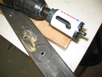
I have to tell you that this hole saw bit was fantastic. It cut through this .065″ 4130 like it was angry. Wow, it cut fast & took no prisoners!
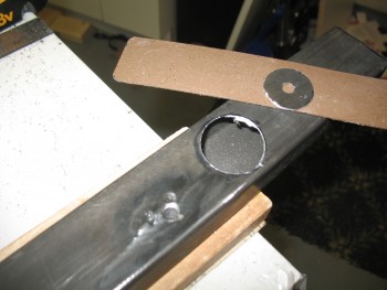
After drilling the top plate of the cross bar, I needed to drill the bottom. I had to be careful here because I knew that the angle would drive the hole saw into the front sidewall of the cross bar. I want the hole on the bottom only, even though it may not be truly circular in shape.
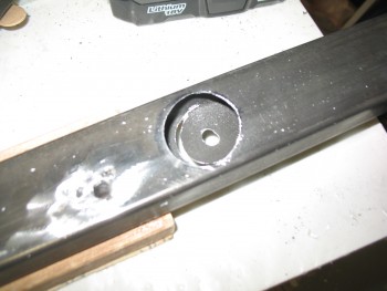
I got as far as I could before the cut got close to the front wall.
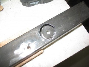
Then I flipped the cross bar over & continued drilling on the underside.
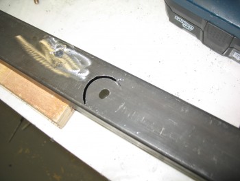
Because of the front wall, I never really got any penetrating drilling action to complete the hole, but I did thin the metal in the area where I would use the Dremel Tool’s cutoff wheel. The Dremel Tool of course finished the job nicely & the hole for the right side roll bar tube was roughly in place in the cross bar.
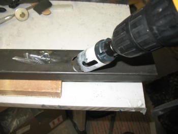
I then tested the fit & angle of the roll bar on/in the cross bar.
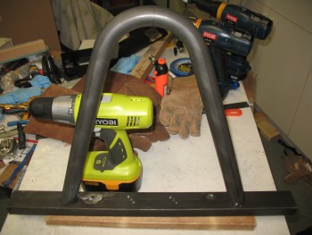
The initial fit of the right side roll bar leg into the cross bar was good.
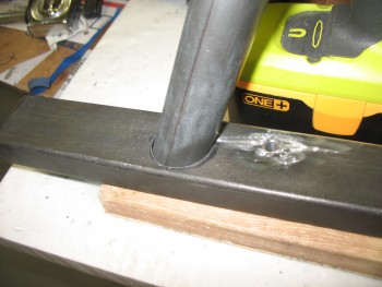
And the angle looked good, but needed to be leaning aft just a bit more.
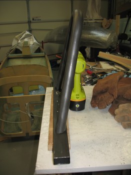
With all the preliminary, nit-noy stuff on the cross bar completed, I was free to tack weld the cross bar to the side rails.
I started this process by putting the cross bar in place, and then installed the headrest so that the headrest bolts supported the cross bar. This gave me 2 things: 1) The alignment of the headrest to the cross bar, and 2) the “natural” position of the cross bar when bolted to the headrest.
Now, to digress just a bit. I have some thin Mica (about the thickness of really fancy paper) on hand that I thought I could use as a heat barrier for tack welding the roll bar assembly as it sat on the fuselage. However, after testing the Mica, it was clearly not usable as a heat barrier. It was fascinating to heat up paper-thick material where it was glowing red, then remove the heat and have it return to its original state as if nothing happened. And only slightly warm to the touch within about 10 seconds.
Thus, I had to carefully plan out my tack welds since I would be making them “off fuselage.”
I started with the left side rail and clamped the cross bar to it on my welding table.
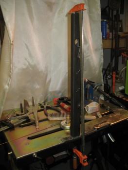
I tack welded the cross bar to the left side rail in 3 spots.
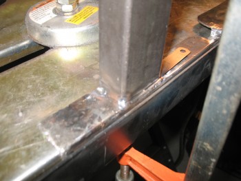
I reground some Tungsten electrode tips as I let it cool before mounting it back on the fuselage.
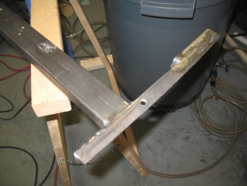
And then after a myriad of measuring, sightings, drawn lines & mystical visions, I set up the weld for the right side rail & clamped it all into place.
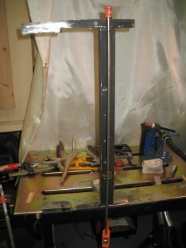
And here it is. Somewhat of a historical moment for me since I’ve waited literally years to tie all this together!
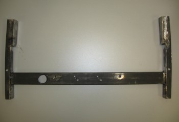
When I installed the new cross bar/side rail assembly, it went in REALLY tightly. I carefully removed it & trimmed each edge of the seat back shelf about 0.05″ on each side, concentrating mainly on the front half of each side and tapering off so very little of the edge was cut at the aft edges of the seat back shelf sides.
After trimming the seat back, I was able to install the roll bar base assembly nice & EZ.
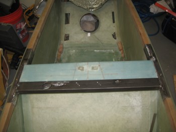
I of course installed everything I could to check out fit, finish & style! Thus far I’m extremely pleased with how it’s all coming together.
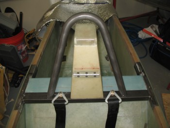
After a million and one grinds & regrinds on the roll bar legs . . . and checking the symmetry about the headrest, I finally got the roll bar frame to a point of my liking and decided I should fire for effect!
Since there’s some space between the cross bar & the seat back, I decide that here was definitely a spot I needed to tack weld the roll bar where it sat on the cross bar, on the fuselage. I set up the welder . . . and voila! The roll bar is now official!
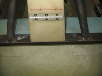
Here’s the first official pic of my new ROLL BAR!
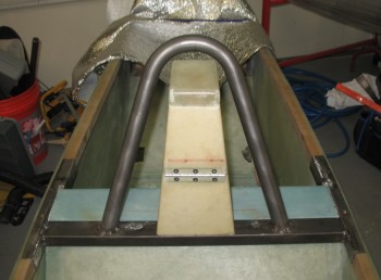
From the side . . .
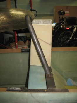
And an angle shot.
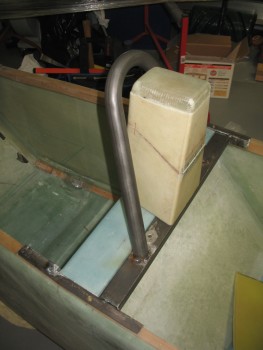
The official height of the roll bar is 13.2″ tall. You may remember that I wanted it no lower than 13″, so this meets my criteria. I think in my mind I was gunning for 13.5″, but it’s still a 1/2″ taller than stock. I think this is a good roll bar height since I really didn’t want a high, towering roll bar looming over the GIB or overpowering the overall appearance of the cockpit “ambiance” . . . if you will.
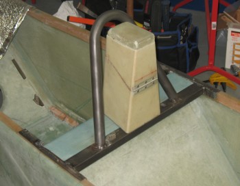
I was really ready to go to town & tack weld this assembly in numerous places, but it was well after midnight and I knew I had a myriad of pics to download to the computer & upload to this site. And I certainly didn’t want to make any gross welding errors in my tired euphoria.
So I said goodnight and turned out the lights.
•••
5 April 2015 — Today was all about cutting & welding in the 2 support tubes that connect the roll bar to the aft seat side rails. Obviously, instead of the “traditional” Long-EZ roll bar with 2 cross fuselage tubes, I chose to go with only 1 rectangular cross bar (tube). I still wanted the added support coming from aft of the main roll bar, but since I don’t have a rear cross tube, I needed to dive mine into the side rails.
I’ve seen a few other EZ bubbas with this design, and I like it because it allowed me to use a heavier main cross tube, that fit my design wishes, but still keep the roll bar assembly as light as possible.
To cut these support tubes at the top where they intersect the aft side of the roll bar, I picked up a cheap (~$37) Harbor Freight tube notcher when it was on sale a month ago. I had been looking around for a good tube notcher, but don’t work with metal enough to spend a bunch of money on one. This one definitely has its idiosyncrasies, so anyone looking to pick one of these babies up make sure you watch the YouTube video(s) on how to modify it so it will cut decently straight (you basically need to add a plate or 3 washers to get the pivot-mounted pipe holder piece to line up with the hole saw blade). That being said though, it really works well!
To double check the tube notcher, and to get an idea of where to even start angle-wise, I pulled up the Tube Coping Calculator from MetalGeek.com. I got this link from my buddy Marco when he used it to help build his roll bar. I also have it linked on this site under Planning & Prep → Project Preparation.
Yesterday when I went on my hunt for drill bits, I picked up a piece of 3/4″ PVC pipe to use as a test piece to help figure out my cuts for these support tubes. Obviously with the multiple angles, I need all the help I can get.
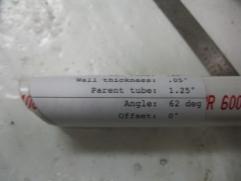
I got a rough measurement of the angle from the side rail up to the roll bar, and plugged that into the coping calculator. My first angle read was 33º, but when I printed out the coping angle template, it was clearly way off. So I flipped it around and printed off one for 57º. Clearly much better, but I still needed to add a few more degrees. I added 5º for a total of 62º and that seemed to do the trick.
With the top angle seemingly in hand, I had to confirm it by locking in the bottom cut to allow the tube to dive into the aft side rail. I simply sighted the tube from straight above, marked it and then cut it. Below is the final outcome after a few minor mods to get the shape locked in.
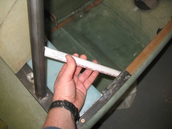
And a view from aft:
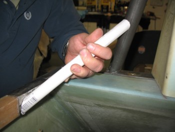
With my PVC template for the left side aft support tube ready, I now wanted to confirm that my tube notcher worked properly by cutting a piece and comparing the results. I set up the tube notcher & made the requisite modifications so that it would cut straight. I then cut the other piece of PVC to compare the notches.
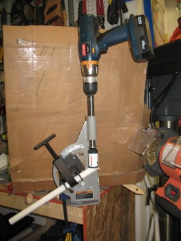
The notch on the left is the Harbor Freight Tube Notcher, while the notch on the right is from using the Coping Calculator template. Interestingly enough, when I set the tube notcher, I had switch back to 28º (vs 62º) to get the same cut angle.
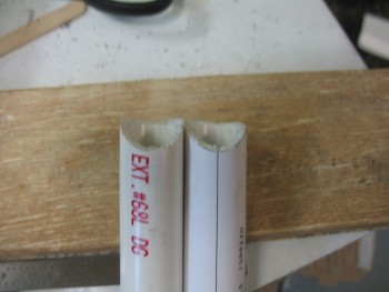
With tests & confirmations under my belt, it was go time. I threw a support tube into the tube notcher and just like on the cross bar, this bi-metal hole saw went through it like it was nothing . . . except nothing like HOT STEEL! It took about 6 seconds to realize that I definitely needed to be wearing welders’ gloves to work this baby as it spit out a myriad of tiny chips of hot steel.
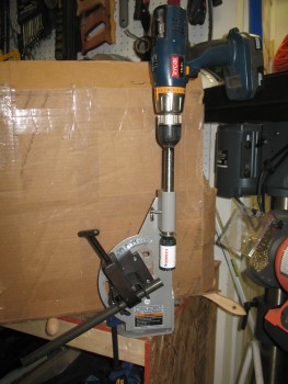
Here’s a pic as its cutting.
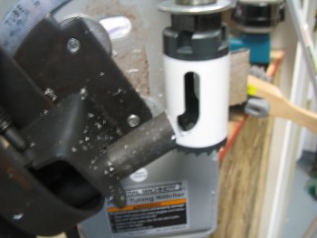
And when the monster is finished . . .

And here’s the fit of the cut . . . fantastic! Amazingly nice cut for a $37 tube notcher!
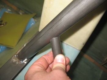 Here’s another shot of the notch fit from the Tube Notcher.
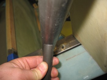
I spent the next hour cutting out the right side support tube, lining up the top notch & the lower cut that dove into the aft side rail. It was a constant repetition of grinding the bottom side of the support tube to align it with the aft side rail, then re-notching the top just a hair, until I finally got the right fit.
I then held it in place while I tacked welded it to the roll bar first, then the side rail next. I should add a note here that I used a heat shield under the side rail made up of a small piece of mica, folded in half over a piece of aluminum foil… and guess what?! It worked!! No burnt glass or burned out epoxy. Apparently in the correct thickness, mica does work magic.
BTW, holding the support tube in place while also holding the filler metal rod with the same hand took a little bit effort. At one point I seriously thought about moving stuff around to pull out my MIG machine. In addition, after my first tack weld last night, I made it a point to switch the control from the foot pedal to the hand switch for better maneuverability & control.
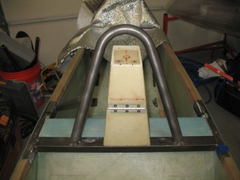
An angle shot of the support tube.
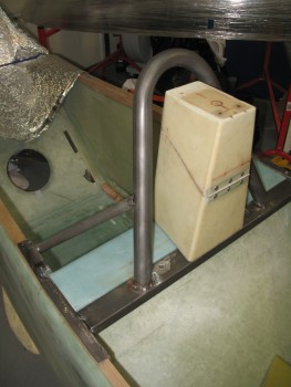
And a closeup.
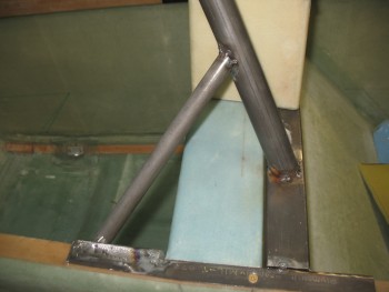
And finally, an aft view.
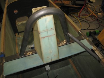
I then took a quick break & ran to–where else?–Harbor Freight to pick up a 20 gal sand blaster that they have on sale.
When I returned, I repeated the process on the left side to make & install the support tube.
The next two pics shows the entire roll bar assembly all tack welded together!
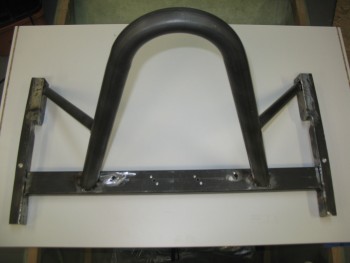
Once the roll bar was completely tack welded, it pulled the aft side rails in just a hair. So the 0.05″ that I didn’t shave off the seat back shelf sides before, finally came off. Actually, I took about 0.05″ off the entire edge of each side of the seat back shelf, and it worked like a champ. The roll bar slides freely in & out without catching on that darn seat back edge.
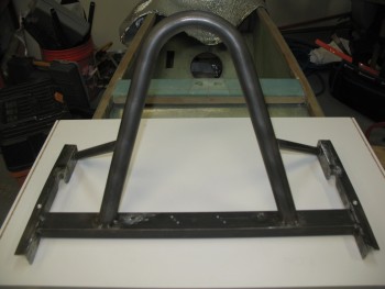
And the final steps all started with this PVC template right here:
I spent the next few hours welding up the roll bar, and still have just a bit left to weld. The process I followed was that I would weld one area like the top intersection of the left cross bar & side rail, and then switch to the underside of the top part of the right support tube where it intersected the roll bar, etc.
After every 4-6 area welds, I would let the roll bar assembly cool & then remount it on the fuselage to ensure that the alignment was still correct. There’s some very, very minute warpage that occurred, but nothing that won’t disappear as soon as it’s bolted into place.
Also, some of you may be wondering if the support tubes might interfere with the sides of the canopy. Since my canopy is much wider than stock, the canopy frame will be narrower than stock as well. I accounted for the canopy frame when I designed the support tubes . . . to a degree. I may still have to have a slight notch on each side of the canopy frame to clear these support tubes, but nothing that isn’t manageable.
•••
6 April 2015 — Just a quick update. I was prepared to do a full day’s worth of work & finish up the majority of the roll bar when I had friends stop by unexpectedly.
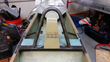
Before my visitors arrived, I spent about 45 minutes cleaning up all the welds with the Dremel Tool and a half dozen cutoff wheels. I then switched to heavy duty abrasive pads on the die grinder, which kept my air compressor in a constant ON state for another 45 minutes.
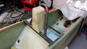
I’ve said it a myriad of times, and it seems to hold true: I’m an ok weldor, but I’m an excellent grinder! Ha!
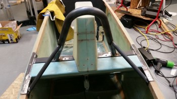
Hopefully tomorrow I can get a bunch more done on this roll bar assembly.
•••
7 April 2015 — The first thing I did out of the shoot this morning was to spray the front corners of the roll bar with weldable primer. These corners, at the corner of the cross bar & the side rails, will get a small angle piece welded into place for a little bit of added strength.
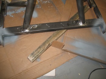
Here’s the leftover piece of the cross bar that I cut off when I fitted the cross bar in between the side rails. I cut 2 angled pieces out of it to create the angled corner reinforcement inserts.
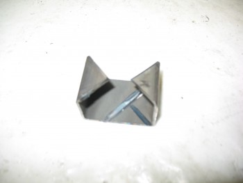
Here are the inserts after I cut them out of the leftover cross bar piece.
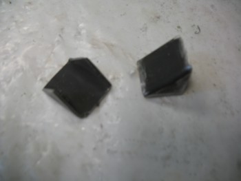
And here they are after I welded them into place. Technically, after I welded them in place, made a half dozen clean up welds, welded some spots that I missed, and a whole lot of grinding & disc sanding the weld junctions.
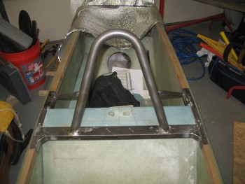 I then marked the side rails with the locations of the 1/4″ mounting bolts. After verifying that the locations were good, I drilled the side rail mount holes 7/64″ with the roll bar off. Then I mounted the roll bar & drilled the mounting holes through the longerons. I checked that each hole was drilled level, so that each bolt would be level when mounted.
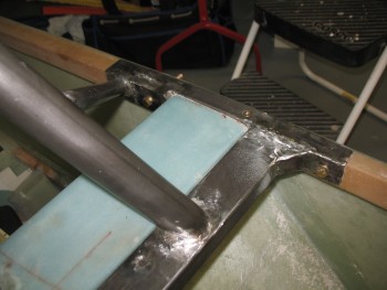
Here’s a pic of the left side 1/4″ mounting bolts set in place.
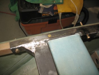
And another front shot showing both the corner angle inserts & the 4 total 1/4″ mounting bolts.
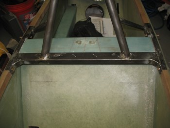
Here are the left side mounting bolt holes shown from the outside of the fuselage.
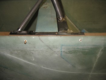
•••
8 April 2015 — I forgot to mention yesterday that I got some important keys. One set, the cam lock & keys, is a recent requirement and is for the headrest opening, while the other has been on my list to acquire since 2012, which are the keys for the Newton fuel caps that I bought back then.
I’ll be installing the cam lock in the headrest after I finish finishing the roll bar. That will pretty much be the last official task of Chapter 8!
Ok, speaking of Chapter 8. My goal today was to sand blast the entire roll bar in prep for mudding up the nasty weld spots with bondo, and then shoot it with its first coat of primer.
I unpacked the handy dandy cheap-o sand blaster that I bought from Harbor Freight the other day.
After threading together a million (and one!) connectors, I finally had the darn thing put together.
I situated everything outside, ran the hose from the air compressor, got all my protective gear ready, and the bag of blasting media that I also picked up when I got the sand blaster.
I poured the media into the sand blaster tank until it was about half full, then did one final double check on the lines, tubes, valves, etc. It all looked good so I was ready to make this roll bar look good!
And man did this thing work like a champ! It was a very fine spray but it just peeled all the nasty crap & mil scale right off . . . for about a minute! Then it jammed.
I got it unclogged and got about another 45 seconds out of it, and then it clogged again. I thought maybe I needed to use a bigger tip, since I had loaded the smallest one in the gun since I was using fine blasting media.
The slightly larger tip worked like a champ! For about 45 seconds again. I messed around with this thing for about a half hour & then declared no joy.
I wasn’t sure what exactly was going on, but I was sure that I didn’t want to be in sand blaster troubleshooting mode, I wanted to be in roll bar finishing mode. So I quickly packed up all the sandblasting gear and stowed it away.
Back inside, I was clearly reverting to MANUAL mode. I grabbed a few sanding boards and a bunch of sandpaper–all mostly in the 120-150 grit range–and started sanding away. I concentrated on the welded junctions at first, to allow me to get the bondo out & cover up some less than beautiful welds. Now no one will ever know! HA!
REMEMBER: If ya ain’t cheatin’, ya ain’t tryin’!
I slathered up all the areas with bondo that needed some cosmetic assistance, starting on the left half first, then while all that cured, I worked on the right half. By the time I had finished bondo’ing the right half, the left half was fairly cured and ready for cheese-grating. If you’ve ever worked with bondo, you know that when it’s fully cured it’s a bear to work with & sand. If you knock off the high points while it’s still just a TAD soft and ever so slightly gummy, it makes life a lot easier later on.
After I finished cheese-grating all the bondo’d areas with my 36 grit sanding board, I went to dinner.
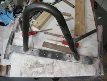
After returning from dinner, I grabbed some more sandpaper and spent about an hour finishing up the contour sanding on the bondo’d areas.
Once the bondo’d areas looked good, I grabbed some slightly finer 180 grit sandpaper and knocked off all the mil scale on every area of the roll bar assembly.
With the first major round of sanding & contouring completed, it was time to give this puppy a thorough scrubbing before it got its shot of primer. After hitting it with the air blower and shop vac, I grabbed the acetone & went to town.
Let me tell you, this thing was filthy. The paper towels I used were simply turning a heavy black as I went 3 rounds on the entire roll bar assembly with the acetone.
So . . . when I did a bunch of painting on my motorcycle project, I learned a trick from a few old skool painters: The final prep before shooting any paint or primer is simply, Simple Green. It’s natural and leaves no chemical signature to mess with the paint. It, as its name implies, simply cleans and nothing else. So, I cleaned the roll bar frame one last time with a round of Simple Green, and then got it prepped for Primer.
Here’s the last shot of the Roll Bar Assembly in its natural state. Goodbye 4130 color, we’re gonna bring sexy back! HA!
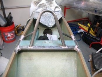
Uh, ok, we’ll bring sexy back later, but for now we’ll settle for this brownish-red primer. Of course this will serve as merely the first primer coat, with much of this getting removed as I sand it down and do some spot touch-ups with bondo for one final clean-up before the final (Gloss Black) primer coat gets shot.
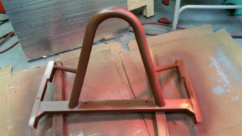
I of course couldn’t resist mocking thus sucker up to see what it looked like installed. Here’s the final pic of the evening.
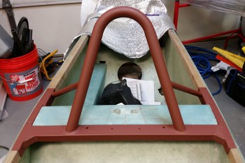
Tomorrow I plan on trimming the side rails so that they’re slightly radiused on the lower corners front & aft, final sanding the roll bar and shooting the final black primer coat, and getting the nutplate assemblies installed & floxed into place for the 1/4″ roll bar mounting bolts.
•••
9 April 2015 — As with any finishing project, today was all about sanding. And more sanding. I sanded down all the bondo’d junction areas that needed to be cleaned up. The tops of each side rail especially needed sanding, as did the cross bar to side rail junction, and of course the rollbar to cross bar attach points as well. Basically anywhere that had bondo applied got a good resanding, or fine tuned at a minimum. I spent a good 1-1/2 hours working on this part.
I also grabbed my Dremel Tool with a cutoff wheel and radiused the front & rear lower corners of each side rail. Rounding off these corners provides a number of benefits. It keeps the corners smooth to avoid snags, scratches or nicks on people, clothing or gear. It also adds to the appearance of the roll bar assembly, in my opinion. And finally, it does help save just a little bit more weight.
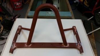
I then applied more bondo. I really dislike having to add more bondo because even though it seems like you’ve got it feathered out just right between the bondo and the surrounding metal, it will show up that you don’t–glaringly–under paint. So, I did the the necessary evil and applied another round of bondo in the problem areas, knowing full well that it will require some touch up sanding and a reshoot of the final primer.
[Note: I used Evercoat’s Metal Glaze on my motorcycle chopper project as a transition filler and it works wonderfully & is very EZ to use in feathering a seamless transition from bondo to metal. At this time however, I just didn’t want to spend the time or the money (it’s expensive stuff!) to get some, so I’m trudging through this part of the build in true neanderthal fashion!]
I spent almost an hour cheese-grating the new bondo, then about another hour and a half on the final sanding. After hitting all the touch up areas, I sanded down the entire frame to smooth out any imperfections & to give the next coat a surface to grip to.
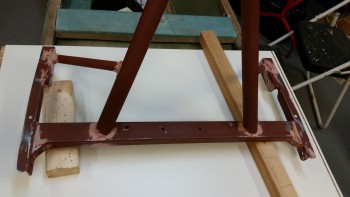
Once I cleaned up the roll bar & prepped it for its second/final coat of primer, I started by shooting the bottom side first this time. With the reddish-brown primer I didn’t shoot the bottom since it only needs one coat for corrosion protection and doesn’t need to be refinished for aesthetics sake.
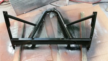 As the bottom side primer cured, I went to work on cutting out the 4 “diamond” pieces of 1/16″ thick 2024 aluminum that will serve as the base, or glorified washer if you will, of the nutplate assemblies.
After much thought & a lot of pondering over the past month, I decided on this style bolt installation to allow for a strong, yet very light, install. To meet my design criteria, I made these aluminum “diamond” bases because I didn’t want the K1000-4 nutplates [that will be used to retain the roll bar mounting bolts] to simply sit bare on the opposite side of the longeron from the bolt head. I figured something that provided a more base-like structure, along the lines of an odd-shaped washer, would help spread the load of the nutplate & keep the nutplate from getting compressed or digging into the longeron. Since 2024 aluminum is incredibly strong stuff, than 1/16″ should work just fine.
To keep the nutplates & their associated 2024 aluminum “diamond” bases from spinning as the attach bolt is installed, I simply used aircraft grade aluminum rivets embedded into small pilot holes drilled into the longerons (remember, there’s a couple layers of glass on the outboard side of the longeron as well). The entire nutplate assembly, along with their securing rivets, will get floxed into place with the 1/4″ AN4 attach bolt holding everything in its proper position.
Once I cut the “diamond” pieces, I Alodined them.
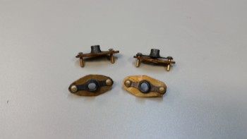
To give you a visual depiction of what I’m talking about, I whipped up a diagram to show you just what I mean. One note: the rivets will actually be installed at a slight angle from the horizontal on each side of the bolt, compared to how they appear to be depicted below, which is 180° straight up & down. Again, when the install process of these nutplate assemblies is complete, they will be awash & embedded in flox in every possible nook & cranny, except (hopefully!) the actual bolt end on the outboard side.
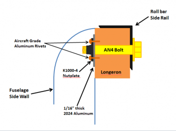
After my adventures in Alodining were complete, I hung the pieces to dry and went back to work on the roll bar.
I set it upright & shot the final major coat of black primer (technically Rustoleum Gloss Black Primer & Paint). After allowing it to dry for a couple hours, I reshot the side rails & some of the bondo’d junctions to provide a little bit more build for the subsequent sanding & reshooting that will be required to smooth out the surface & joint imperfections.
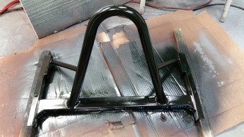
After a few more hours and with the black primer coat dried, I mocked it up on the fuselage.
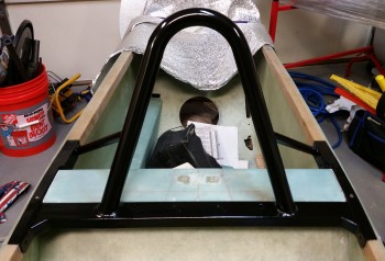
I have to say that I’m extremely pleased with the way this roll bar turned out. As I mentioned before, I still have a few more hours of work finalizing the finish on it, but overall I’m one happy camper!
•••
10 April 2015 — I started off today by installing the left side nutplate assemblies with the rivets reversed so that I could get them as close to the fuselage side as possible.
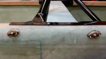
I then traced around each nutplate assembly to get as close to a perfect outline as possible for the cut into the fuselage side glass.
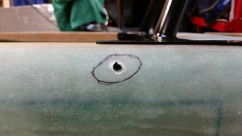
I then cut the glass along the marked outlines using a Fein tool.
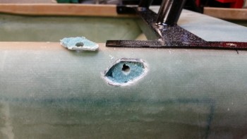
And then I dug out the glass and cleaned up the glass on the ‘back wall’ of the nutplate cavity [which of course is the 2 plies of glass on the inside fuselage wall].
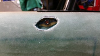
I mocked up the 1/16″ 2024 aluminum reinforcement plate with the nutplate so that the rivet holes aligned, then I drilled the rivet holes and installed the rivets.
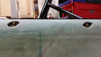
Up until this point I had been using longer bolts to be able manipulate the nutplate assemblies & remove them more easily when I needed to. But when the rivets were set, I removed the longer bolts and installed the actual AN4 bolts that would be used for the installation of the roll bar assembly.
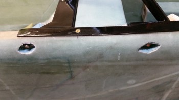
Here’s a shot from inside the fuselage of the actual AN4 1/4″ bolts installed.
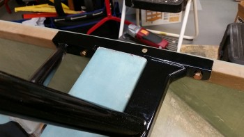
With the left side nutplate assemblies ready to be installed & floxed into place, I started on the right side of the fuselage to get those nutplates ready for installation.
I put the fuselage in a left bank to help me install the right side nutplate assemblies.
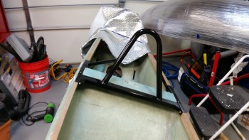
Just like the left side, I marked the outlines of the right side nutplate assemblies.
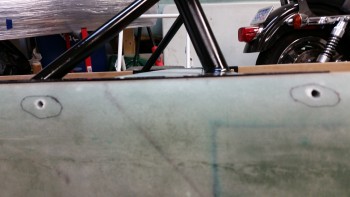
I then cut away the glass, dug out the foam and cleaned up the back wall of the nutplate cavities.
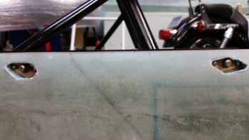
With the installation of the correct 1/4″ AN4 bolts on the right side, along with the left side secured in place, it was time to flox in place the right side nutplate assemblies.
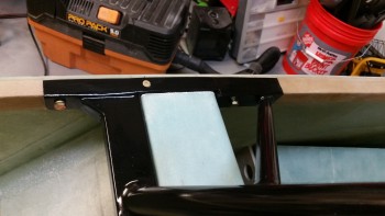
To install the nutplate assemblies, I started with a flox slurry. It wasn’t too runny, but it definitely wasn’t paste. I did have flox paste on hand as well to finish off the holes. When I got to the end of installing the right side nutplate assemblies however, I had pretty much filled each hole with flox–since the holes weren’t that big to begin with.
An issue I was having, although I had used fast hardener and leaned the fuselage at an angle, was that the flox was slowly oozing out of each hole. For about 10 minutes I kept scooping up the oozing flox & squeegeeing it back into its respective hole.
As I was thinking about something to keep the flox in place, I realized that I could simply use the outer skin of the fuselage that I had just cut out. It was exactly the same shape as the hole it came out of, and moreover, it had the exact right curve of the fuselage so that there would be no flat or odd spots on the edge of the fuselage when I re-glassed it later on. I cleaned up the underside of the first piece of ‘diamond’ skin that I had removed, and when I pressed it into place, I knew I was on to something.
With the flox mess around the hole & all over the reattached skin piece, I knew that I would employ the help of one my old friends: PEEL PLY! I ended up putting both outer skin cutouts back into place and securing them with peel ply. Also, the peel ply helped soak up all the flox and epoxy mess that was around each hole.
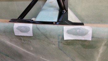
While the flox was curing on the right side nutplate assemblies, I pulled out some scrap UNI to cut out for the 2-ply UNI reinforcement layup that I will be doing on each longeron over the freshly installed nutplate assemblies. Since the outer edge of the nutplate assemblies are 10″ apart, I’ll be setting the first ply at 12″ (1″ past the edge of the hole) and the second ply at 14″ long, so that it goes 1″ past the first 12″ ply.
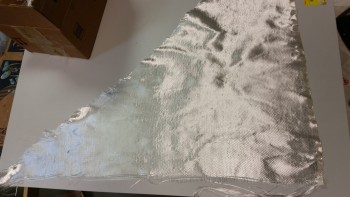
Here are the 2 plies of UNI glass for each side of the exterior longerons. I’ll need to cut one more piece of plastic to set up these pre-pregs correctly.
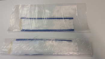 Here’s the cured right side nutplate insert assemblies. They set great and you can barely feel any difference between the reinserted exterior skin pieces and the old skin. This will work much better than I thought, and reduces the steps on this task from 3 to 2.
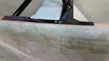
I then leaned the fuselage in a hard right bank to work on the left side nutplates.
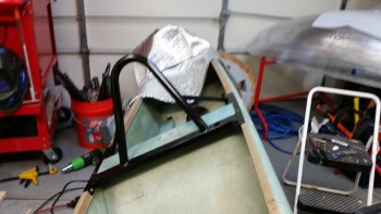
Here’s a long shot with the nutplate cavities ready to get their fill of flox.
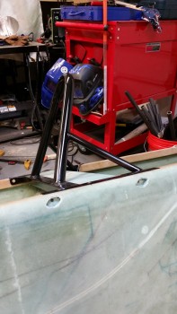
And just like the right side nutplate assembly installation, I re-installed the removed skin pieces. If you look closely at the pic below, it looks like a pair of eyes, thus, the eyes have it . . .
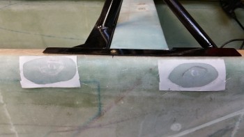
•••
11 April 2015 — I started today by pulling the peel ply from the flox & fuselage pieces that cover the right side nutplate insert assemblies.
 And then the left side.
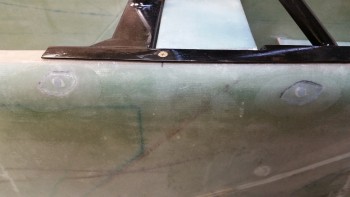
After sanding down both sets of flox covers for the nutplate assemblies, I then laid up the pre-pregged 2-ply UNI strips on the right side fuselage. Of course I peel plied it afterwards.
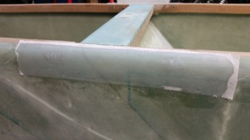
And then did the same on the left side fuselage. The first UNI ply was 12″ long, and the top was 14″ long.
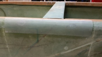
While the fuselage sides were curing, I started work on the seat back in preparation for glassing in the lower seat back piece. The first task was to trim the piece hanging down to 1.3″ wide. I marked the cut line with a Sharpie & trimmed it with the Fein tool.
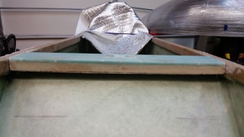
I prepped the BID tapes for installing the lower seat back by sorting through my BID scrap bin & then cutting out the required pieces. I then cut the correct size plastic pieces and set up pre-preg assemblies for the BID tapes.
Here’s the lower seat back curing after the first round of layups.
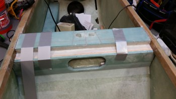
While the initial round of BID tapes cured on the lower seat back, I pulled the peel ply on the right side nutplate assemblies’ UNI layup & cleaned it up.
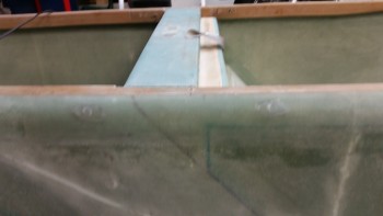
And then of course did the same thing on the left side.
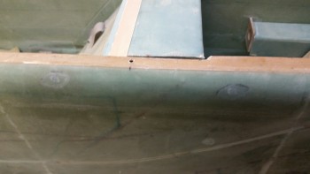
Here’s the lower seat back after the peel ply was pulled. The duct tape in the middle is a reminder to trim a strand of BID that is sticking out from under the peel ply… which certainly will cure to be spike lying in wait for my finger!!
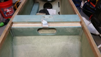
I then mocked up the roll bar to check the fit of the width of the cross bar in the notch created by installing the lower seat back.
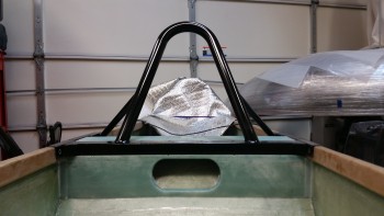
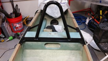
•••
Chapter 8 is complete!
12 April 2015 — Yes, I’m calling Chapter 8 completed! I may hold the record for the longest completion time for Chapter 8 in the history of canard building, but oh well! There are a few more nitnoy cosmetic things that need be taken care of, but structurally & functionally the components for Chapter 8 are finished!
I started off today by pulling the few bits of remaining peel ply from yesterday’s BID tape layups on the lower seat back. I then took the orbital sander to the seatback to help clean up the mess I had made during that gunky, sticky, tacky layup yesterday. Some days it just seems like you’re nothing more than Pooh Bear with honey stuck all over you, and that was this layup for me yesterday!
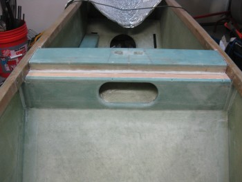
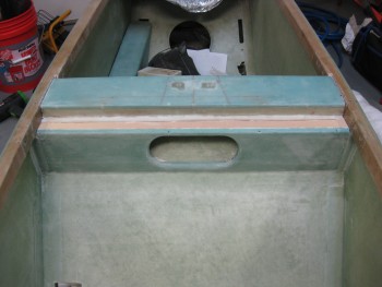
I took some measurements for the final BID piece that would make up the final layup on the lower seat back install. I had to go to the cutting table to lop off a piece large enough for this layup.
I pre-pregged mainly so that the line on the bottom edge would be fairly straight across, and would remain that way as I tugged and pulled on the layup around the curves on top. I figured it would also help in dealing with the oval hole in the center of the lower seat back.
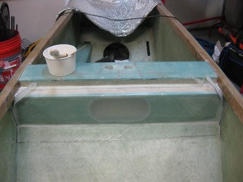
The pre-preg did seem to help a great deal when I cut out the BID to make a smaller hole in the middle of the oval shaped hole.
Also, in the pic below I’m ready to remove the plastic, and after shoving the glass into the upper corners at the glass shelf and longerons, the plastic easily just peeled right away.
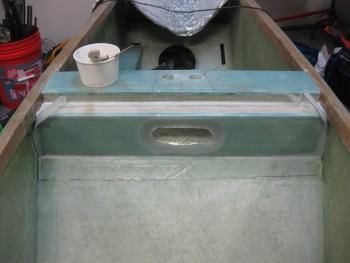
And here’s final layup of the lower seat back piece!
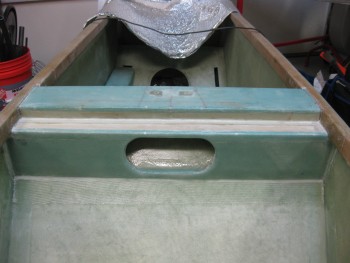
I did spend about another hour peel plying this layup, with my main concentration being on the edges of the oval hole. To help keep the glass to stay in place on the edges of the hole, I poured some of the epoxy I had on hand into another cup and threw in some Cab-O-Sil. It seemed to help, but the peel ply seemed to help a lot as well to keep the glass in place.
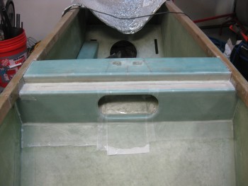
Here’s a view of the finished top cross bar notch.
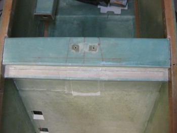
I then set my sites on installing the cam lock into the headrest. Once I determined how the lock was going to sit inside the headrest, I started whittling away the foam to create a channel for the lock arm to rotate into… and for the lock body to sit in as well.
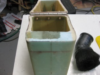
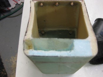
I didn’t want to make the aft inner wall too thick (for clearance of the lock mechanism), so I laid up my first ply of BID so that it covered only the floor & aft wall of the channel.
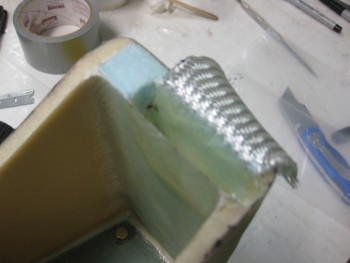
Then I added a ply of BID that covered the floor of the channel and all 4 sides.
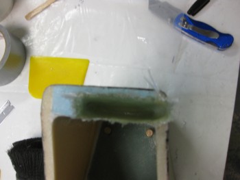
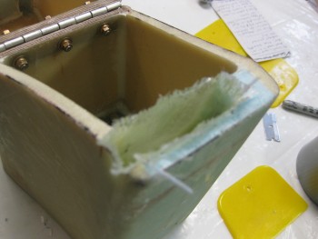
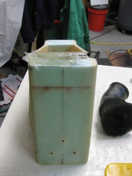
And to keep the flow of this step, I jumped ahead with the out-of-sequence pic below to show the finished lock channel layup.
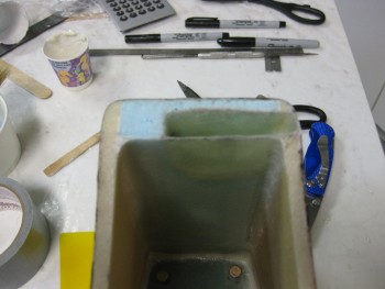
I pretty much had to do the mirror image on the upper headrest piece, since the lock arm would swing up into the upper headrest to snag the lock pin.
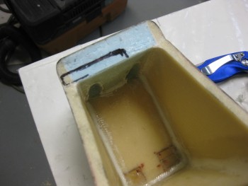
Thus, again I made a decent mess by carving out some more foam.
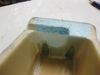
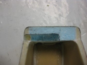
I then marked the install location for the cam lock on the lower headrest piece.
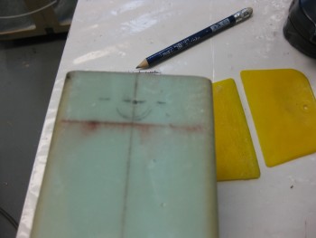
And drilled the 5/8″ hole.
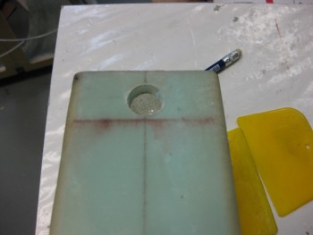
I then dug away more foam to create another channel between the very aft headrest wall, and the aft wall of the cavity that I had just created for the lock swing arm.
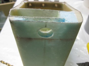
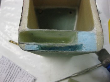
I used a scrap piece of 1/4″ Finnish Birch plywood & drilled a 5/8″ hole in that as well. The plywood will serve as a reinforcement plate for the lock, whilst all of it will be embedded in flox inside the new cavity I created on the aft headrest wall.
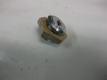
I dry fitted the plywood lock reinforcement plate.
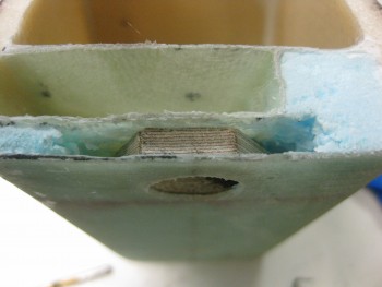
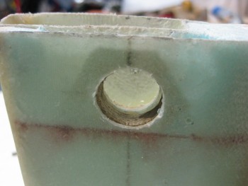
And also dry fitted the lock.
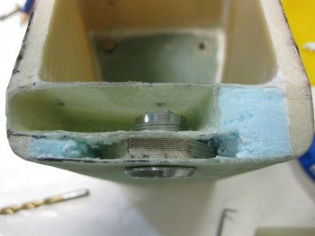
Now, not shown in these pics is the thick black line on top of the lock to ensure it got placed upright in the mounting hole with the lock slot vertical when it was locked. The cavity for the lock swing arm however was just a hair too angled on the outboard side, so the swing arm didn’t sit down all the way. Well, somehow in working the install, I somehow lost site on my lock orientation line, and when all was said & done . . . oh, and FLOXED . . . I had installed my lock [again, IN FLOX!] into the headrest 90° from where I had intended to set it. So my key doesn’t align with the position of the lock arm.
Oh, well. Worse things have happened, and often minor screw-ups like this turn into fun war stories later on. At least I still have vertical and horizontal key positions, versus some random funky angle!
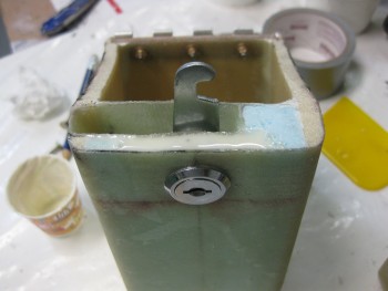
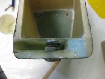
I then turned back the upper headrest to mount the lock pin. I cut off some uber heavy duty wire (I don’t remember what this stuff is for, but it may as well be a roll of steel rebar!)
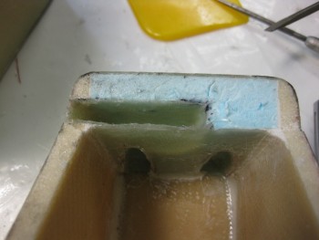
The one bad thing about having a roll of really strong metal “wire,” is that when you cut it, it’s still curved! I spent about 20 min trying to get the curve out, and finally gave up when it was real close to straight.
Although I very carefully measured & prognosticated where the lock arm would hit the lock pin, I was off just a hair and had to move it over about 0.065″. To keep the lock pin in place in the now oval-ish hole, I used a drill bit. Then, after multiple, multiple trials of locking the headrest, I knew that the lock pin was in the right position. But before I could whip up some flox to secure it, I had to swap out the drill bit for a disposable and embed-able toothpick.
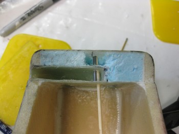
Here she is all floxed up.
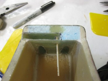
And the whole headrest assembly showing some of my work for the day.
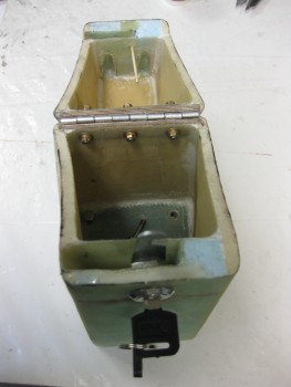
As the flox on the headrest lock pin was curing, I re-mounted the roll bar assembly, using all bolts & screws to ensure nothing had gone majorly wonky from glassing the lower seat back assembly. I did have to do some sanding & shaving in the left corner of the cross bar shelf, but after a little bit of time the roll bar slide into place.
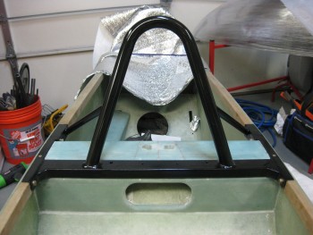
Here’s a long shot view of the glassed lower seat back & the cross bar assembly.
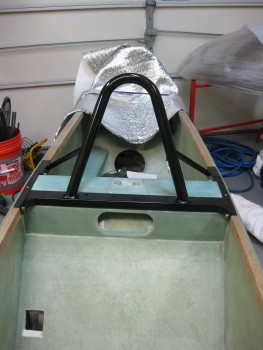
And I top level view to show the alignment of the lower seat back with the cross bar (the pic is offset just a little).
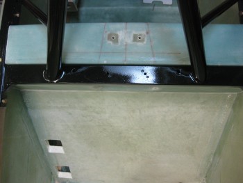
And the final shot of the evening shows the gap between the cross bar and the seat back shelf
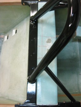
•••
Chapter 8 Wrap-Up
13 April 2015 — I started this morning by cleaning up the flox from installing the lock pin into the upper headrest for the lock mechanism. I also cut the retaining toothpick in the areas that it was showing. The next time I whip up some flox I’ll put a couple drops on the interior side lock pin attach points to add a little strength.
I’ve been thinking that I will probably add some type of lightweight rubber/bungee positive attach clasp so that I can simply reach back before flight to ensure that the headrest top is held closed by feel. Obviously I can’t do that with the lock, and although it works well, I don’t want the lock to be the only thing keeping the top of the headrest from flopping forward when I hit my airbrake at Mach 2.0!
You can see that I also installed the RAM mount. In my last order from Aircraft Spruce, I picked up a medium and long arm for the ball mount.
I also picked up a universal tablet cradle that should handle any 7″ sized tablet. Here I have my iPad Mini mounted. At least initially, I think the long RAM arm should work well back here. Unfortunately, the area immediately behind the roll bar frame is the only area where I can position the canopy cross bar, so the RAM arm decision will have to wait until after the canopy is installed.
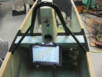
Here’s a side view of the GIB RAM mount setup.
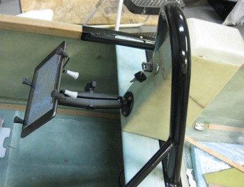
Here’s the view for the GIB:
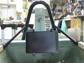
And a shot of the headrest opened up.
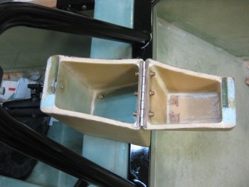
Front view of the open headrest.
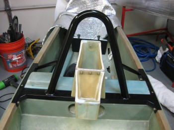
And a shot of all the Chapter 8 stuff I just spent the last 6 weeks working on!
You’ll note that the seatbelt bolts don’t sit down in the holes like they should since I have to still drill 2 quick holes in the bottom cross plate of the notch that sits just below the cross bar. This will give me access to each seatbelt attach bolt so I can put a socket on the underside nut to bolt it into place.
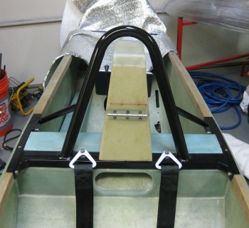
And here’s just couple more shots from the GIB’s POV.
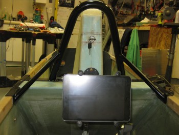
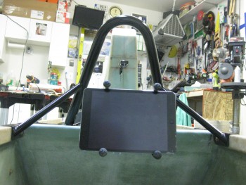
I will do a final light sanding of the roll bar to smooth out just a few rough spots that are left, and then reshoot those areas with primer/paint.
Ahh, which reminds me! The final weight of the rollbar assembly with primer/paint is 5.95 lbs. Add 0.17 lbs. for the attach hardware (including embedded nutplate assemblies) and the total weight for the rollbar is 6.12 lbs. Of course there’s a few ounces of added glass & flox, so I think calling it no more than 6.5 lbs total added weight installed wouldn’t be a stretch.
•••
14 April 2015 — I did some research on paint for the rollover assembly (and possibly the instrument panel). I want a very nice quality, professional-looking roll bar, but I’m not looking to shoot it with a two-stage polyurethane or anything like that. Also, because I’m using bondo to clean up the seams I can’t powder coat it, which I wasn’t really looking to do anyway. I like the idea of having a paint job that looks great, but that I can change the color somewhat easily if I want, and that can easily be reapplied if I need to modify or add something later (like the tab for the pneumatic canopy stay).
Thus, over the last few days I’ve gone into backyard mechanic mode and have been researching rattle can clear coating for the roll bar (Yes, I can here all the groans, gasps & sighs now! HA!). Again, something that will make it look great, but is also somewhat EZ to maintain.
Now, my thought for the aft roll bar support tubes is that they will serve 2 primary purposes: 1) (rare) buttress the roll bar if the roll bar (God forbid) ever gets called into real action, and 2) (common) used by the GIB as hand grips for ingress/egress of the bird.
With the hand grip piece of the puzzle in mind, I was thrilled when I not only ran across Rustoleum’s FLEXiDip, but that it had it’s own version of clear coat that could shine it up with the rest of the roll bar. FLEXiDip provides whatever it’s applied to a rubbery surface for gripping. Sounds perfect for the roll bar support tubes in my mind!
To test it out, I grabbed an old rusted pipe that I use as a cheater bar.
I then hit it with the wire wheel to clean it up for my test shoot.
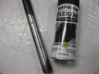
And I then shot a number of thin coats on it (as per directions).
Here’s the FLEXiDip when it’s dried (no clearcoat . . . yet!)
And another shot with a bit more contrast to see it better.
BTW, the texture is not a thick rubbery feel, but it’s definitely “softer” than regular paint. Pretty cool. I also picked up another brand, Plasti Dip, that I’ll be trying out in a head-to-head runoff for the best rubberized coating.
•••
15 April 2015 — Before taking off the roll bar assembly & headrest, I wanted to mock up the canopy to see what it looked like (as best possible with the canopy wrapped in plastic). I mounted some wood cross support pieces for the canopy & locked them in place with clamps.
Here are a few pics of the headrest & roll bar under glass . . .
And a longer shot of the same.
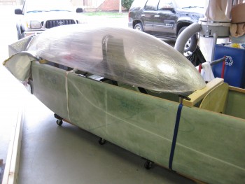
I used a coupon yesterday for a 3/8″ air ratchet from Harbor Freight. I wanted it specifically for using on the roll bar bolts, among a ton of other stuff.
When I hooked up the air ratchet up to the compressor, I discovered something about my air compressor that I think had a significant impact on my sand blasting session the other day. The air coming out of the hose reel is not nearly as powerful as if I hook up a hose directly to one of the other 3 ports on the compressor manifold (I have a 4 ports available to hook up tools, one of them obviously being connected to the hose reel). I’ll need to keep that in mind when I set up the sand blaster again.
After removing the roll bar assembly, I drilled out the seat belt attach bolts access holes.
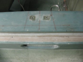
I started with a small 1/16″ drill bit and worked my way up to a 1/2″ bit for the final hole sizes.
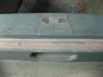
To reiterate, these holes will allow me access to the underside of the rollbar cross bar to get a socket onto the nut holding each seatbelt bolt in place.
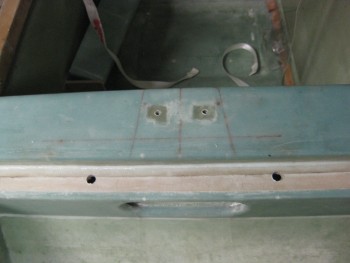
•••
3 November 2015 — While finishing the top of the canard with micro I of course mixed up too much micro for the job. I’ve been really trying to identify small, fast “to-do” items that need to completed with extra amounts of epoxy, micro or flox, and the mating edges of the headrest is a perfect example of one of these mini-ancillary projects. So, expecting at one point that I might have a case of too much micro on hand, I was ready this time to implement my ancillary mini-plan and Dremeled out the foam on the edges of the headrest halves.
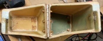
Here’s the micro applied to the headrest edges.
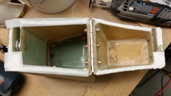
I then peel plied the micro, closed & locked the headrest and then weighed it down to compress the micro as best possible.
•••
4 November 2015 — After a couple hours when the micro had cured to a green state, I pried apart the two halves of the headrest by slowly & carefully inserting straight razor blades around the entire sides & back side of the edges where I applied the micro. A big oops here and thank goodness I caught it in the green stage, because this would have been near impossible if the micro had fully cured. I thought that the peel ply would make it so the two sides came apart with the typical & gratifying peel ply tear off, but this was a solid cure and turned the top & bottom “halves” of my headrest back into one solid piece. Yes, if it ain’t one thing it’s another! Ha!
That’s 30 minutes of my life I’m not getting back!

•••
19 October 2016 — The shot below shows one of 2 pieces I cut from the 2024 bar stock: a 3/8″ x 3/8″ x 1.2″ plug that will go into the end of a 1/2″ x 1/2″ 6061 square tube that I’m using as a crossbar for the GIB top seatbelt straps. Since riding in the back of Marco’s Long-EZ, although not bad at all, I can see where there could easily be a need for folks to bring the top seatbelt straps in closer together.
My bar will be secured in 3 places: on each side with the forward engine extrusion bolt into the CS spar as the original plans upper seatbelt bracket tabs were. And then in the middle of the bar into a hard point in the CS spar. These 2024 square plugs will reinforce the hollow tubing for the 1/4″ AN4 bolt that will get installed vertically through each side of this bar to hold it and also, more importantly, secure the engine mount extrusion in place to the CS spar.
(Note: the two brackets in the center of the pic are the wheel pants inboard mounting brackets).
•••
3 November 2017 — Today, again, was an unseasonably warm day . . . but I suspect that won’t last long. Yesterday was as well but I wasn’t mentally prepared to get something ‘on-the-block’ and painted. Today I was.
I figure my current tasks are such that I can do them in the garage as long as I have heating of some sort. Painting is a different animal however, and unless I want the entire shop filled with paint fumes for a good day or two, I like to get painting done outdoors.
So I started off today prepping my pilot seat headrest for paint. I considered removing the hardware but that would be too much of a pain, so I simply covered it all with blue tape. I then gave it the once over and did some light sanding and hit it with a flat razor blade in some spots to get the surface smooth. Then I gave it a good wash down with Simple Green, rinsed it well and then dried it off.
I took the headrest outside, hit it with 2 light coats of primer as you can see in the before & after pics below.
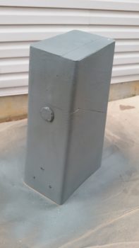
I suspected that I was going to run out of the darker Valspar Sand Stone top paint –which I did after 1.5 passes– so I picked up another can the other day while I was out. But an odd thing occurred that I’m not sure if I’ve seen before. The cans had different lids both in shape and color, yet the cans themselves were identical, with the same name, model number, etc. Yet still, the paint was DIFFERENT, and did in fact match the color and texture on the lids which you can see are clearly different. I tried shooting a test patch with the new paint, and sure enough it was different… how odd. Good thing I noticed and didn’t dive right in and continue painting the headrest with a slightly different color!
A little later I brought the headrest inside. Interesting how dark it looks under shop lights vs. out in the daylight.
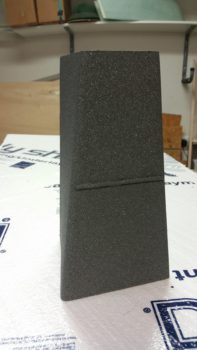
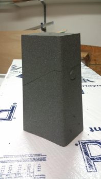
•••
26 January 2018 — Today I got some rubber “T” molding that is used at the edge of auto windshields and the window frame for sealing a windshield edge. I bought it off of Ebay because it was the only source of supply I cold find (I looked a while!) and had it shipped in from China. I checked it out a bit, then I trimmed it and mocked it up atop my pilot seat headrest (which will get repainted with my now standard interior scheme color later). The molding looks like it will do a great job for it’s intended purpose of securing the GNS480 GPS antenna puck cover (aka “radome”) in place, given that I don’t have any glue, tape or anything securing the pieces together in the pic below.
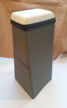
•••
3 May 2018 — Today was the first day in a LONG time that has been warm enough for painting. Since my pilot headrest was still taped up from the first round of painting this was definitely low hanging fruit. [You may remember the cans of spray paint, although labeled the same, were distinctly different colors so I dumped my 2-tone cabin paint scheme and am simply going with one color]. I painted a couple of coats of the gray granite on the head rest and then after about 4 hours I hit it with a couple of coats of matte clear coat. A few hours later, when the clear coat had cured to the point to allow handling, I removed all the protective tape from the headrest.
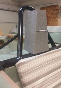
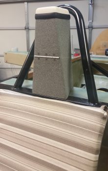
I then attached the RAM air ball with a screw and put the keys back in the lock (mainly in an attempt to help keep track of all this stuff!).
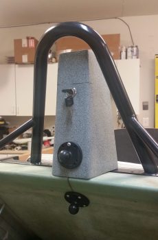
I then set the GPS antenna “radome” back on top… just something for a little fun and to spark some conversation at fly-ins! (grin)
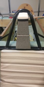
•••
15 August 2020 — A minor issue I’ve identified is with the canopy gas spring attach point. Not an issue with the gas spring or geometry or operation itself, but the fact that the hefty mo-jamma canopy is pulling the back end of the rollbar rail up slightly when the canopy is open. Note the visible gap I have the red arrow pointing to in the pic below.
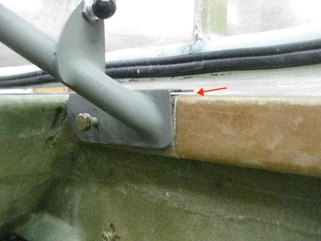
Here’s a view of the top of the rollbar attach rail, aft end,
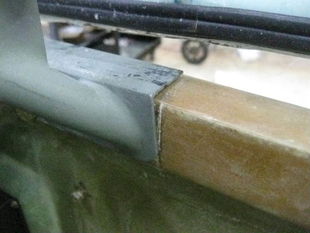
Now, Murphy always seems to extract his commission on what appears to be a simple screw installation on the rollbar rail…. But here’s where protracted builds start showing their ugly side.
My thinking was that before I drill a hole DOWN through the longeron I wanted to ensure the roll bar rail was installed SNUGGLY to the longeron with all the bolts in place. I had on hand some fancy stainless steel hex-drive cap screws for the final install of the rollbar. I even had 4 of them (2 front, 2 aft) in a baggy marked for that purpose.
I’m going to jump ahead here pic wise to show the bolt configuration of my rollbar: one 1/4″ bolt on the front side of each rail, one 1/4″ bolt on the back side of each rail, and one 3/16″ CS screw in the middle area going vertically down into the longeron.
Note different style bolts… key to the story later on.
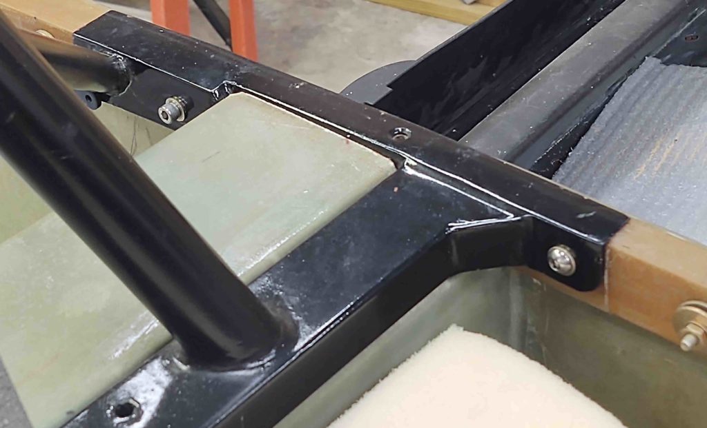
Well, as I kept trying to completely thread in the existing bolt (I had in “finger” tight) and then one of the pre-identified cap head screws into the aft rear bolt hole, I was getting it to thread in, but then at the point to tighten it appeared to be stripped. The bolt would just spin.
I compared the length but must have justified it as correct in my mind since I had identified these bolts as the correct ones. I had used a 1/16″ aluminum plate with the nut plated attached buried into the foam on the external side of the longeron… had it failed?
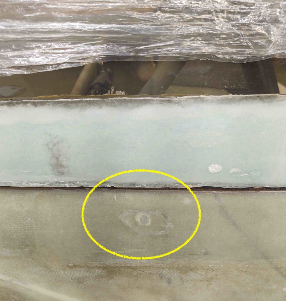
After messing around with it I knew I had to confirm the rollbar mounting point nutplate was good, had not broken loose or was somehow stripped.
So I marked the spot, and then opened it up (sorry, no pic of that).
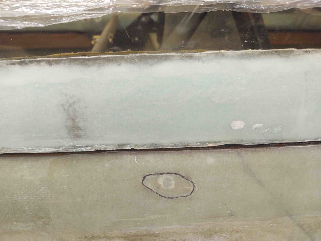
After messing about for awhile what I found was that the nutplate rollbar attach hardpoint was perfectly in-tact and strong… no failure. It hadn’t stripped out either. So what was the culprit?
The bolt was simply TOO SHORT! It was “threading” into the wood of the longeron, making me think it was engaging the nutplate, when it fact it was short of it.
As I point out above, the cap head bolts are 1-1/4″ long for the front. Almost a perfect length (one side was about 1/16″ too long), while the aft bolts required are 1-1/2″ long. This info is probably buried in my notes somewhere, but I found out the hard way.
At least now –after having opened one up after years of use– I have renewed confidence in my rollbar attach hard points though!
Back to my original issue at hand . . .
I gathered up all my nutplate assembly tools and ginned up a phenolic nutplate for a 3/16″ screw.
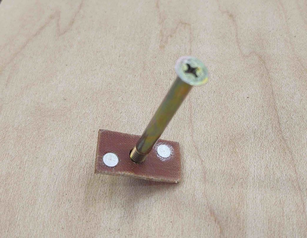
I then clamped down the aft end of the right side rollbar attach rail.
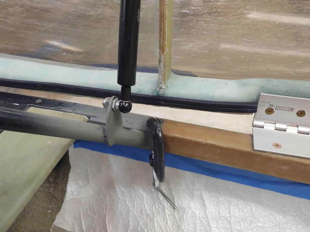
After securing the canopy with a tie down strap so I could get access behind the gas strut, I then drilled a #10 hole down vertically into the longeron, through the top plate of the rollbar attach rail.
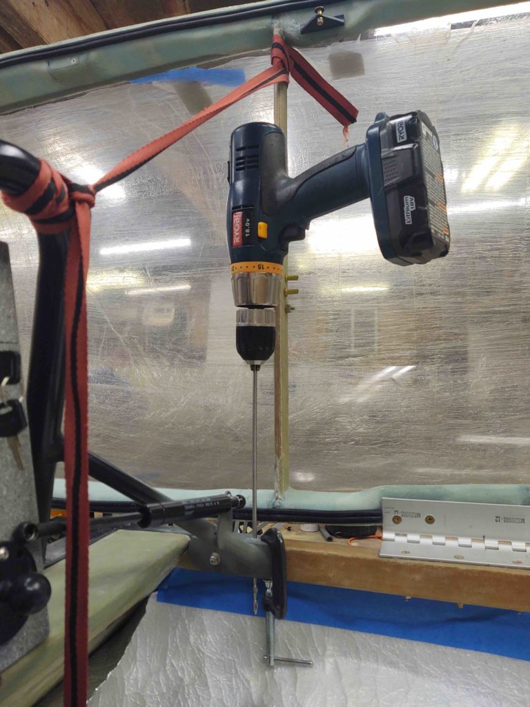
Here we have the resulting #10 hole . . .
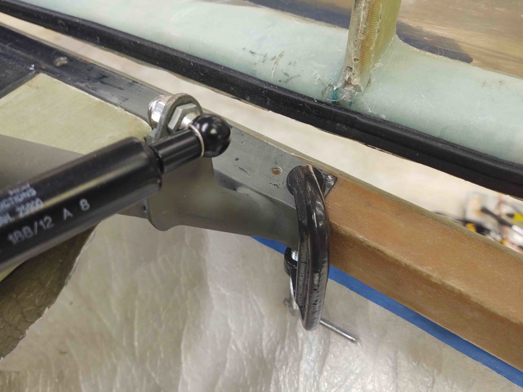
After which, I countersunk the hole.
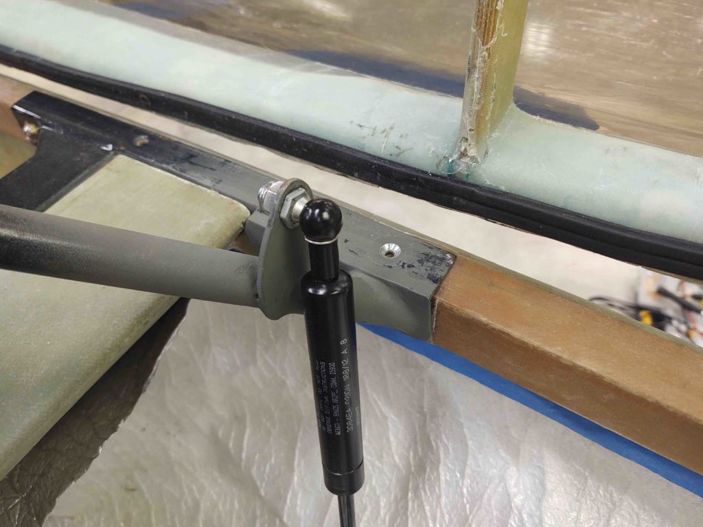
And then test-fitted the screw.
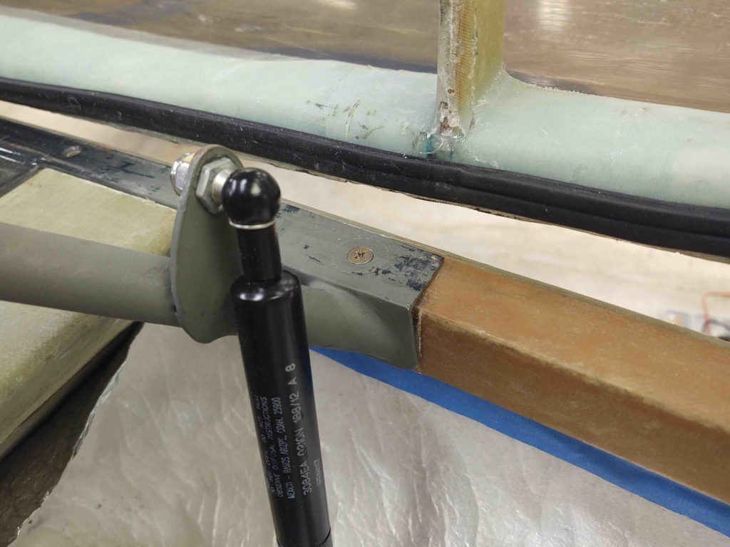
Here you can see a good amount of the screw poking out below the longeron.
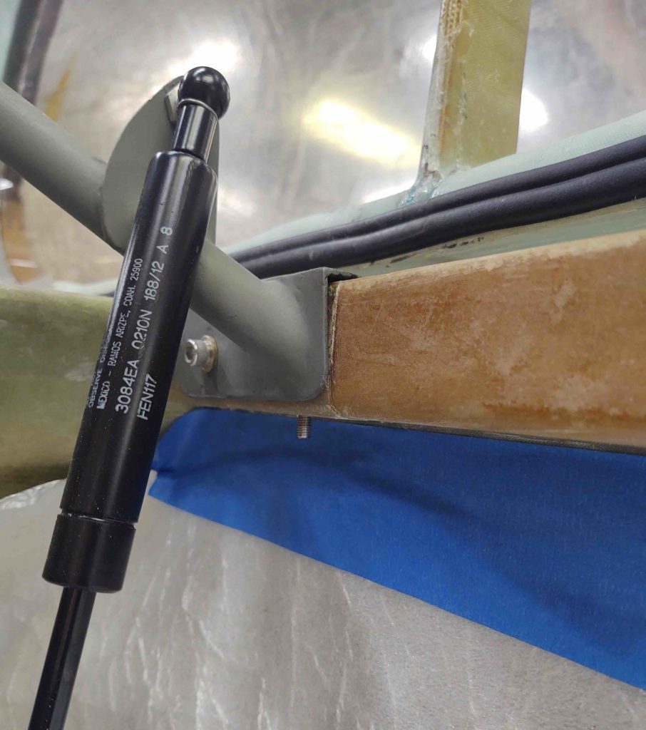
•••
16 August 2020 — Today I floxed in the phenolic nutplate assembly onto the bottom of the longeron for the aft RHS rollbar frame reinforcement screw.
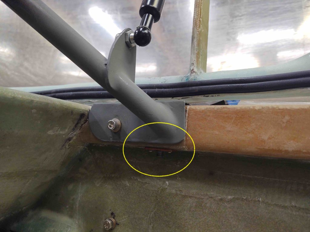
I used a thin washer under the screw head to ensure I could get the screw out after the flox cures, although I did apply a thin coat of grease to the end of the screw threads.
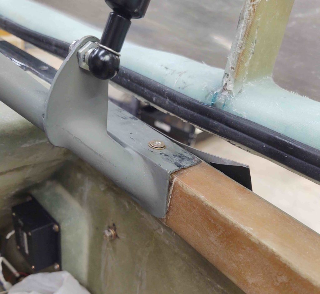
•••
17 August 2020 — Since I was remiss in not showing the removal of the access plug I made to assess the rollbar bolt securing nutplate, here’s a shot of it after I floxed it back into place. I’ll fill the gap in with micro and glass over it with BID tapes when I build the strakes.
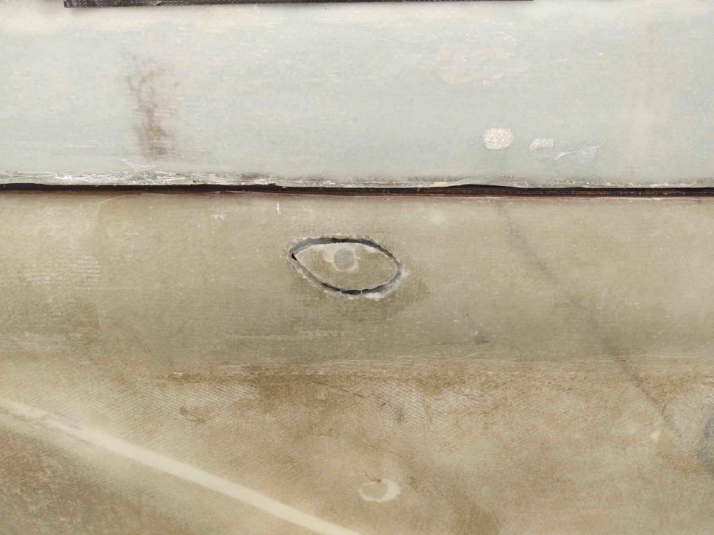
•••