
Main Fuel Tank Probes
(Note: the actual wiring will be under Chapter 22 – Electronics)
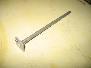
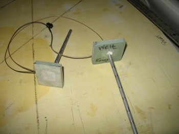
3 May 2014 — This afternoon I was able to get a hold of Master Canardian Nick Ugolini and order a set of his Capacitance Fuel Probes. Nick designed the probes himself to be used in canards and to link up to Princeton Fuel Probe electronics to provide high quality fuel reporting to EFISs, etc.
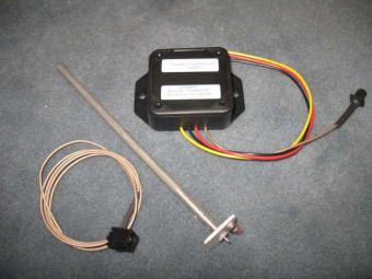
At first I resisted the idea of fuel probes since I already have Vance Atkinson’s fuel site gauges and will be using a fuel flow sensor, but considering that these are just a few ounces a piece including the electronic control boxes, I figured knowing my exact fuel quantity for a total weight penalty of well under a pound was worth it. I had just read too many reports of high praise for this system to ignore it all and not pull the trigger on a set. (I pulled the pics below off of Nick’s blog):
Another motivating factor for installing these early on (i.e. during the build) is that since I’m gearing up in the planning and R&D of building my strakes, it’s just that they’re a heck of a lot easier to install now during the initial strake build than afterwards. Now, that being said, they actually don’t look that difficult to install after the strakes are built, but anything I can do to avoid introducing potential contamination–in the way of bits & chunks of foam & glass, etc–into the fuel system is worth doing early on.
•••
25 August 2020 — I’ve been trying to stuff these fuel tank probe electronics modules into the D-deck –at least mentally– for years! Well, tonight I finally gave up. After one last final assessment, I threw in the towel and decided that they will be going into the Hell Hole.
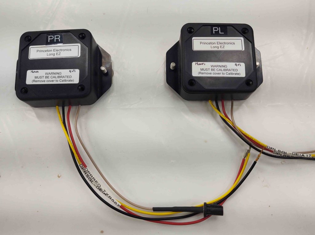
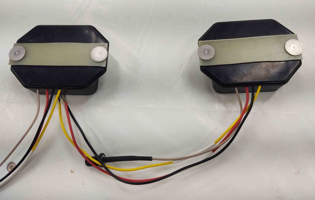
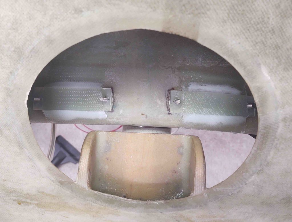
Note in the pic below they are actually set up on the mounts they’ll be attached to in the Hell Hole… technically just off to each side of the center line of the main gear.
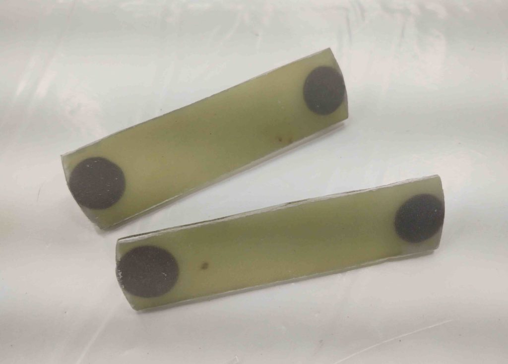
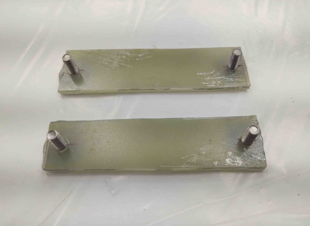
I cut a couple of strips of 1/16″ thick G10 approximately 1″ x 3.6″ wide. I then drilled holes for the mounting click bonds. I’m using click bonds in lieu of nutplates here because these mounting brackets have to sit “flat” on the surface of the gear leg… and when they get floxed into place I didn’t want any of it gumming up any internal holes of the nutplates.
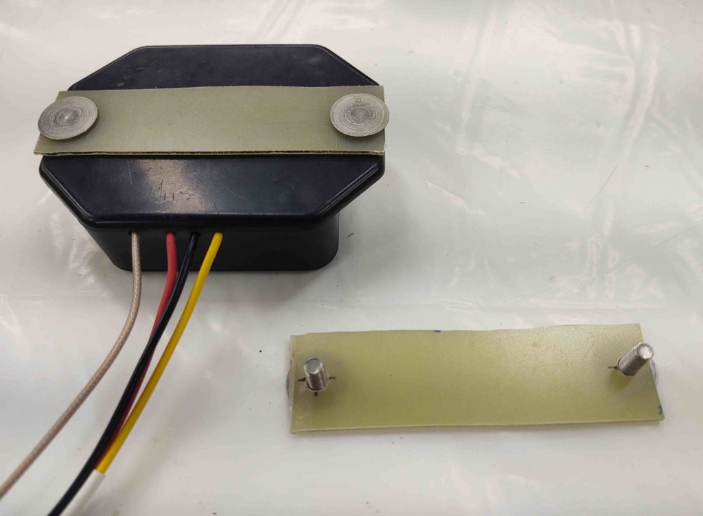
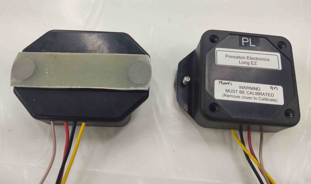
Here’s a shot of the fuel probe electronic’s module G10/clickbond mount both on and off the module.
Yes, a little unconventional, but I then floxed the click bonds to the G10 plates and glassed over the backside of the click bonds with 4 plies of BID.
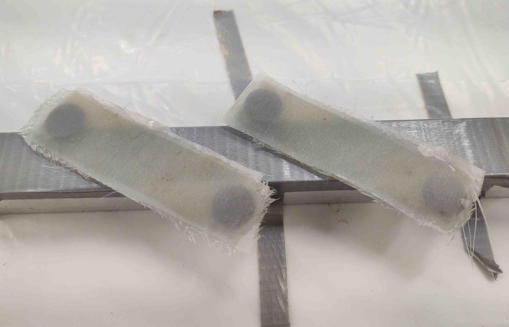
Here you can see the click bonds peaking out on the bottom side of the fuel probe electronics’ modules mount assemblies.
I then peel plied them and left them to cure overnight.
•••
26 August 2020 — I then checked, trimmed and cleaned up the layups on the fuel probe electronic module mounts. They looked great.
I quickly test fitted them one last time to ensure all was good.
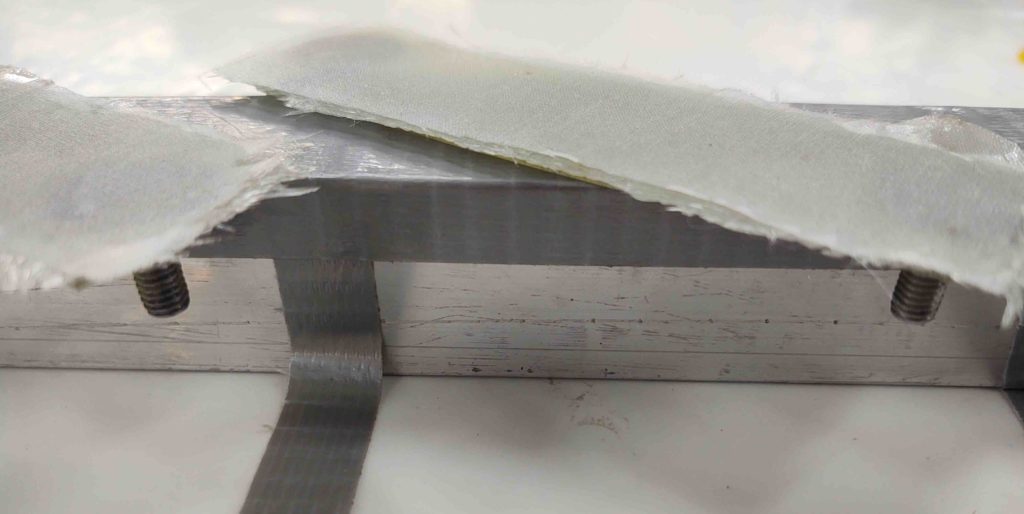
I then flocro’d and glassed them in place on the top of the gear inside the Hell Hole. I used 2 plies of BID to secure them to the gear leg and then left them to cure.
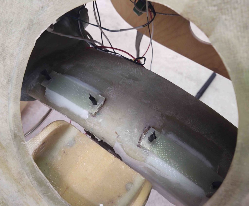
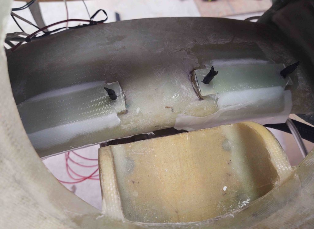
Again we have the fuel probe electronic module mounts nearly 100% cured. So I pulled the peel ply off the front edge . . .
And attached the fuel probe electronic modules on the mounts. I left the cover off the left fuel probe electronics module to show the visibility this configuration provides during calibration.

•••
27 August 2020 — An important lesson I’ve learned in the past when doing electrical system work, is that following the planned wiring diagram is key. It’s like a well-oiled engine with all the parts working in sync. However, if something changes –as things often do– and if I fail to update the plan/wiring diagram and/or forget…. Let’s just say that I have ended up wiring things incorrectly, and spending time un-screwing up what I just did, because I eventually realize something is not right.
That being said, I spent about 1-1/2 hours updating the wiring diagrams denoting the fuel probe electronics modules’ move from the D-Deck down to the Hell Hole. I then reprinted the associated wiring labels and got those all sorted out on the fuel probe wires.
•••