
Chapter 13 – Nose Topside Construction
(This page covers general information on the topside nose view, with the top of nose construction further broken down into the Aft Nose/Avionics Top Deck Cover and the Forward Nose build efforts)
28 May 2018 — Today was really more of a research & modeling day to tie together all the loose ends and integration questions I had regarding the nose. I set up the canopy in its near-final configuration and then got to work on the nose. I took a fair amount of notes and changed my hand drawn plans to account for the finalized dimensions, angles and curves.
Some outstanding questions I answered was that, A) I’m extending the height of F28 0.4″ at the center line, and B) I installed (with duct tape) a 0.9″ gap-filling piece to account for the depression in the Napster bulkhead. When the nose is final this gapped area will be filled by the thickness of the nose hatch.
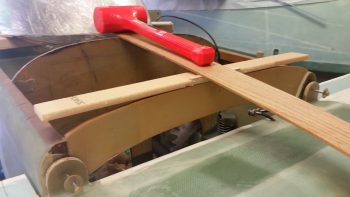
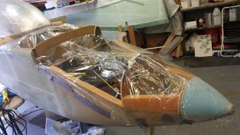
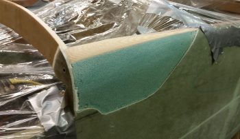
It may be a bit hard to get an exact idea with the big roll of duct tape on the nose, but this is outline of the upper nose.
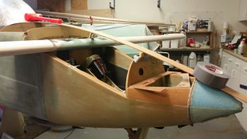
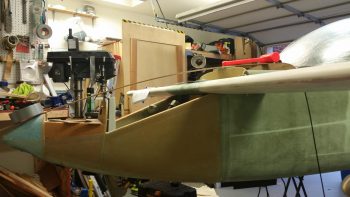
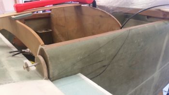
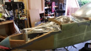
Here’s a shot for the left side. This provides a better depiction of the nose’s top curve.
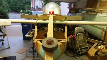
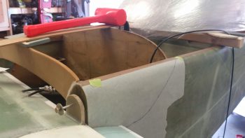
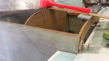
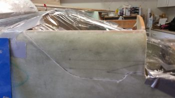
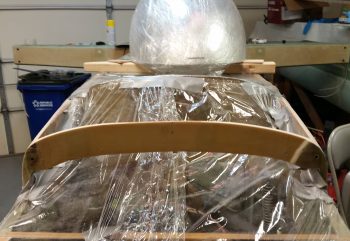
And a shot from the front.
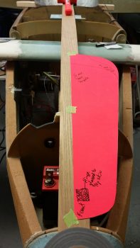
I then taped in place the nose hatch template (which is currently only half the hatch) to assess its size, shape, accessibility, etc. As a point of note, the dimensions and shape of this particular nose hatch template is based off the Berkut nose hatch…. at least it started out that way!
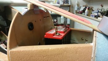
I then set the battery in place to ensure it would fit.
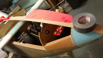
Regarding the battery, I assessed topside cable clearance and clearance for removing and installing the battery. The PC680 battery is around 7.1″ wide and my nose hatch at the narrowest point above the battery with this shape and configuration would be 7.8″ wide.
Here’s a shot of the left side nose hatch template taped in place.
The above is somewhat of a quick overview of my planning process. Again, I took a myriad of measurements, checked angles and clearances, then made quite a few notes and annotated drawings and pics I have of my nose design. There are a number of things that I will cover as I build since it would difficult to provide overviews without pictures of the components and build process.
One such area –that happens to need correcting– is the very front top corners of the fuselage where each side intersects with F28.
•••
29 May 2018 — I started off today taking a gazillion more measurements, and checking out other builders’ sites on their canopy positioning and inboard elevator root fairings. After getting my comfort level significantly higher on the whole of the plan working (at least on paper!) I got to work cutting out some 3/8″ PVC foam.
The first piece was for an intermediate bulkhead that I’m going to install just forward of the canard, which will look bow-shaped and will essentially serve more as both as a bit higher strength cap to the blue foam going in forward of it, and as a demarcation point for the avionics bay/nose cover going aft.
And yes, you read that correctly.
I will be incorporating a flip-up/removable cover for the canard and avionics area forward of the instrument panel and aft of F28. It will also overlap the panel going aft so that the canopy will physically lock it into place when closed (that of course is not the only securing method on the aft side).

More on the avionics bay/nose cover below, for now here’s another view of the intermediate bulkhead that I’ll be securing into place before the nose foam is put in place.
I also cut out a 1.8″ wide strip of the 3/8″ PVC foam that will be the front piece of what is roughly a picture frame looking foam rectangle that will be floxed and glassed in place for torsional strength of the upper forward fuselage between the panel and F28, and the upper longerons on each side. It will essentially be an interconnected “C” channel (just sandwiching foam in this configuration) around the entire edge of the avionics area, with all the glass locking the 4 sides (and corners) together.
Another shot of the nose/avionics bay reinforcement piece, which is the first of 4 separate side pieces to be installed. This design will allow for a significant opening in the top for access to the avionics forward of the panel, which will all be enclosed by the removable cover that extends from the front edge of the canard to just aft of the instrument panel.
I’m aware that this design is deemed a bit controversially by some builders and Canardians, but I’ve studied a number of designs and am mitigating any induced weaknesses to the airframe structure by implementing it. In fact, I honestly think that my design will be significantly stronger that either the plans version or by simply having an avionics access hatch cut in the top of nose just forward of the canopy/instrument panel.
Part of my decision process today was to come to a final conclusion on exactly the design and configuration of the sides of the aft nose and avionics bay cover. My design uses some what of a split elevator fairing where the fairing itself is integral to the cover and then secures to a very robust bottom segment of the fairing via a screw up through the bottom securement tab into an embedded nutplate on the underside notched portion of the fairing.
Where the trailing edge of the elevator fairing intersects the fuselage sidewall and the inherent transition fillet on the underside of the fairing where the determinant dimensions for both the aft and bottom edges of the aft nose/avionics bay cover sides. After RE-reviewing a number of Berkut, Long-EZs and Dave Ronneberg designs with nose hatches, I settled on a simple angled transition from cover to fuselage at the instrument panel external fuselage area.
I double and triple checked all the possible associated variables and potential issues I could think of, and then I made the plunge. I made the final design version on the left side of the fuselage, then traced it to transfer it to the right side.
Which you see is completed here . . .
I then took my wide roll of packing plastic and wrapped up the nose from tip to instrument panel to protect the innards from errant fiberglass, foam and other nasties.
I then loaded a fresh blade on my Fein saw and got to work on my respective fuselage sidewall surgeries. My goal was to cut just enough in depth to cut through the glass and not get into the foam underneath.
If I had any doubts as to how secure my glassing was on the fuselage, this endeavor laid that to rest. It took a good 20 minutes minimum on each side to get the glass pried off while being careful not to damage the foam underneath.
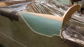
The action here was actually a 2-part task in that not only did it expose the areas on the upper/forward fuselage sides that will allow me to create depressions for the aft nose/avionics bay cover, but also to correct my previous non-shaping of the front “corners” of the fuselage that should have been significantly rounded over before the fuselage exterior was skinned.
In the summer of 2012 I glassed the exterior of the fuselage without having caught the requirement to round the very front of the longeron and nose sidewall foam, as you see that I’ve just done on the right side (left pic below) vs the way I had it (right pic below). Yes, I was living in blissful ignorance until Marco went to glass his fuselage, at which point he queried me about it. I gave him my incredibly well thought out reply of, “Huh?! What are you talking about?!” Followed a bit later by, “Ah, <enter appropriate expletive here!>” To see a great explanation of this, check out Marco’s blog.
As for the aft nose/avionics bay cover, I will be laying up glass back onto this exposed foam area with overlap back onto both the existing fuselage sidewall glass and onto the new aft nose/avionics bay front reinforcement structure (“picture frame”) that will be in place between the panel and F28, and the longerons on each side. This will serve not only to replace the structural element of the previously removed sidewall glass, but tie the fuselage sides to each other via the reinforcement structure.
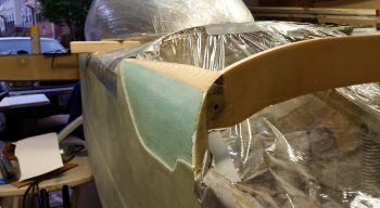
So here’s my shaping the forward top longeron intersections with F28, with the right side (left side of pic) nearly finished and the left side still untouched.
I then finished the forward top longeron shaping to about 90%. I still have to do a tad bit more dialing-in so that both sides match in shape, but it was late, I was tired of sanding and sanding with a hard board is amazingly loud, so I wanted to take it easy on my neighbors and finish the final 10 minutes worth of sanding tomorrow. I also need to finalize the depth of my sidewall depressions in the exposed foam.
Here’s another shot of my shaping the forward top longeron intersections with F28, with both sides shaped this time around.
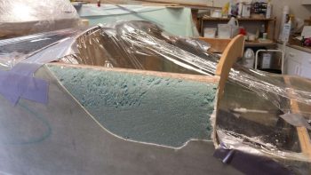
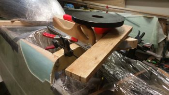
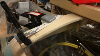
Yes, I should have taken a picture of my shaping and prepping of the aft nose/avionics bay front reinforcement piece before I floxed/micro’d/5-min glued it in place. This pile ‘O stuff is simply to keep the various parts of it weighted down <correctly> since the aft end of this piece is ever so slightly raised to match the downward angle from the panel to the F28 bulkhead.
This contraption (aka “convoluted pile of crap”) right here is exactly why I decided to set the 4 sides of this internal reinforcement frame in individually, since the installation of each side/edge has it’s own unique requirements and challenges. Once all the pieces are floxed/micro’d in place, I’ll do a final sanding & shaping of the new “one-piece” structure and glass it in place as one unit.
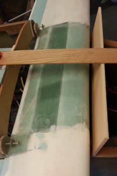
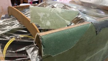
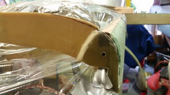
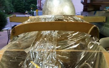
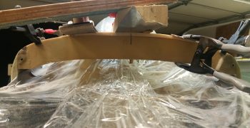
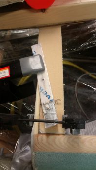
Here’s a straight on view of the aft nose/avionics bay front reinforcement piece. As you can see, the center section is situated and mounted on the top edge of F28, where the outer 30% on each side is then even with the top edge of F28. This gives me just a tad bit more height in the center area of F28 for a good nose angle flow from the panel to nose tip as it traverses F28.
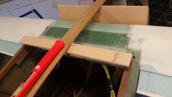
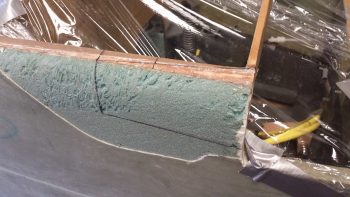
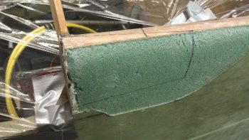
And a couple more shots of the aft nose/avionics bay front reinforcement piece on the left side. The transition from the piece being on top of F28 to simply adjacent F28 is underneath the taped popsicle stick securing the bonded mating surfaces, but you can make out the foam piece floxed in place at the F28-longeron corner junction.
From here on the respective nose builds A) Aft Nose/Avionics Top Deck Cover and B) Forward Nose will be discussed on their own respective pages
•••