
Chapter 15 – Firewall
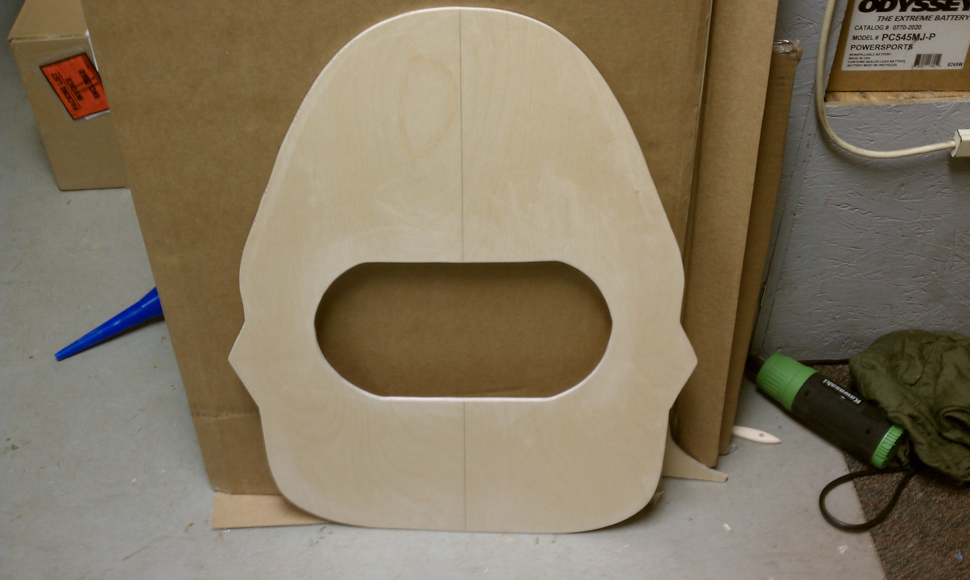
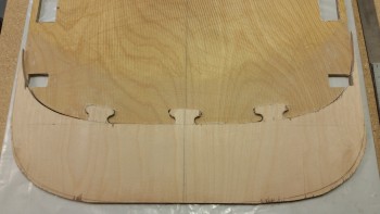
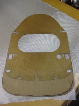
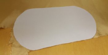
4 May 2011 — Firewall after cutting out of 1/4 in. Finnish Birch plywood.
•••
11 June 2011 — After another few discussions with some experienced Canardians familiar with the old glory days of the Cafe Races, I decided on another modification. Now I’m sure this may very well elicit some groans and ha-rumphs, and maybe even a few mutterings of how crazy I am, to put it politely, but here it is: I’ve decided to go pulley-less and run my rudder cables from Point-A (rudder pedals) through a curved conduit that traverses through the centersection spar, makes a semi-shallow bend and heads to Point B (rudders). No fiberglass strands will be hurt in the making of this modification, just merely slightly separated at the holes in the foam so that glass strength and integrity is still in tact on the centersection spar.
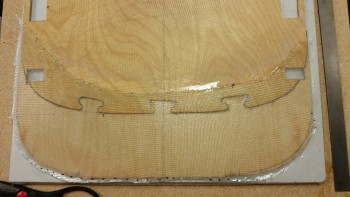
No pulleys means that I don’t require pulley brackets, thus no “ears” on the firewall. So I lopped off the “shoulders” of my firewall.
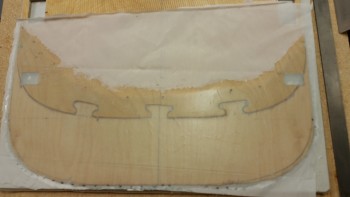
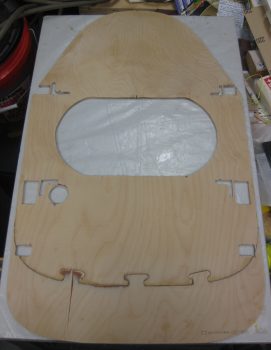
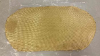
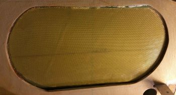
Once I finished cutting the ears off the firewall, I glassed the aft side with 1 ply of BID.
•••
15 June 2011 — I had ordered my Carbon Fiber cowlings from Feather Lite, but with a twist: Mike & Larry were going to put a joggle down the center of top and bottom of the cowling so that I could adjust the cowling widths to my new wider fuselage. Unfortunately, as they played around with the original plugs and molds— [these were the exact same molds that Mike Melvill designed for his armpit scoop cooling design that he installed before his round-the-world trip with Dick Rutan] —they realized that it was just too problematic and difficult to put the joggles down the center of the cowling halves. Plus, it would add significantly more weight, minimizing the benefits and increasing the cost, thus nearly negating the reasons for using CF on the cowlings to begin with.
Thus, I would have to go with the original cowling size, meaning I had to trim my firewall down to it’s original plan-sized dimension. Of course, the firewall being back to its original size does nothing for me if I can’t mount it to my top & bottom longerons… which was the case since my rear seat was widened by 1.2 inches. So I recalculated everything, and not wanting to have go after my front seat (read: cut) I compromised (the art of engineering, eh?) and narrowed my existing modified rear seat back by 0.4″ to only 0.8″ over stock. Which still is a decent amount of extra room in this narrow of a fuselage.
The one effect it did have was that it accentuated the curve of my cockpit to make it even more football shaped (fatter at the center, and narrower at the ends). I’m not an aerodynamicist, but I have had some folks say that my shape is less desirable and less efficient than the original design. Regardless, I think it will still fly even with a potential small increased drag penalty.
•••
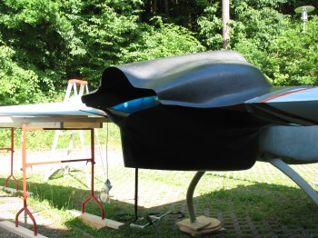
22 June 2013 — Before I was separated from my project while I spent a year in the Middle East for Uncle Sam, I wanted to get an idea of what this thing looks like put all together.
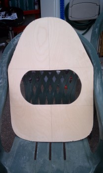
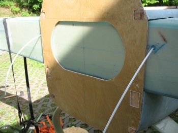
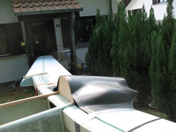
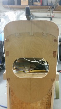
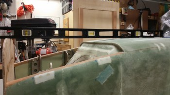
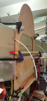
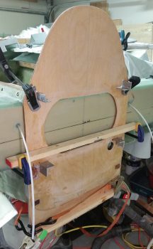
So I pulled the fuselage out into the front yard, and kept it covered while I collected the other components. Below you can see the CS Spar and Firewall mocked up on the fuselage.
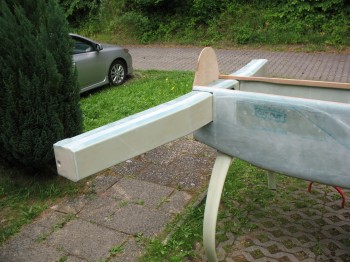
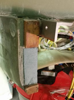
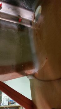
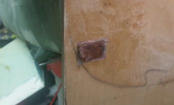
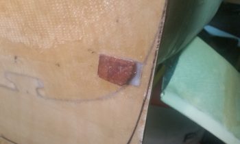
You can see in the pic below that I got the measurements correct for running the rudder cable conduit through the fuselage sidewall, then through the CS Spar and positioned just off the edge of firewall (the curved metal conduit bracket that the Nylaflo will run through will get mounted to the firewall).
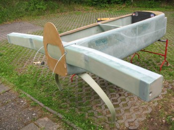
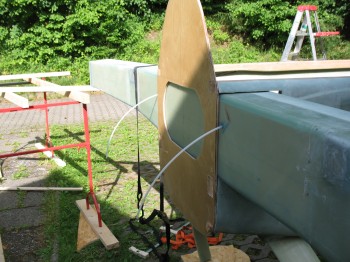
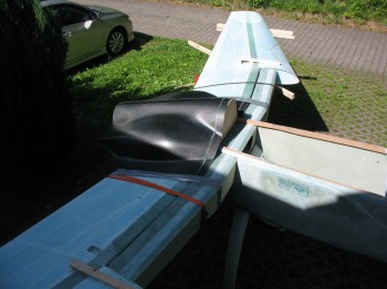
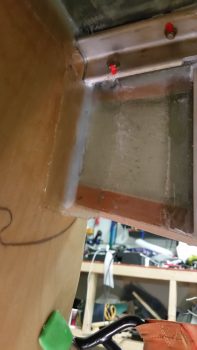
A few more pics of the mocked up firewall.
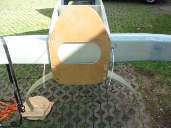
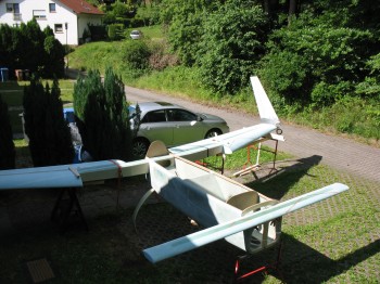
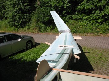
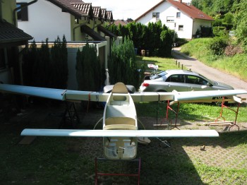
After I got the CS spar & firewall in place, and added the wings, canard, and winglets, I took some wide angle shots. Here’s a couple wide angle shots with the firewall clearly seen temporarily installed.
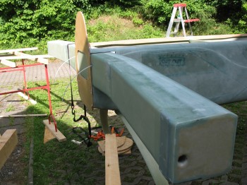
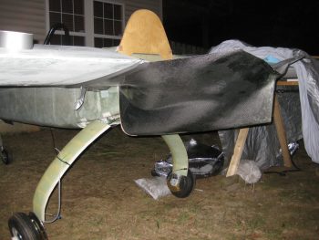
Once I got the pics above taken, now it was time to fill in what gaps I could to make it look at least a little like it had some mass to it. Next came the engine cowlings.
 You can see how the lower cowling hangs down 4 inches below the stock/plans firewall. Again, since Mike Melvill had built a NACA inlet for his engine air intake the back end of his fuselage–and subsequently the firewall–was 4 inches lower than plans [in essence making the bottom line of the fuselage continue straight until aft of the firewall].
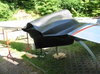
And then the following pics are more close-up shots of the upper cowling & firewall interface.
•••
2 February 2016 — If you look back at the pics I took of the firewall back in 2013 above, you can see how the lower cowling hangs down 4 inches below the stock/plans firewall. As I explained above, Mike Melvill left his NACA air intake in place when he converted to the new carbon fiber cowlings. Thus, his new cowling was 4 inches lower than plans which makes my lower cowling 4″ lower than my stock height firewall. Since I decided to not cut up a perfectly good cowling (at least not yet!) clearly there’s a 4″ gap that must be filled in.
So, today I started work on cutting the required firewall extension piece.
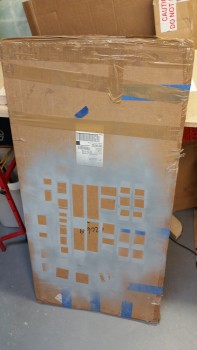
I pulled out the box containing my 6mm (1/4″) Finnish Birtch plywood. The plywood box being easily spotted… recognize it? It’s the box that I primed all the 2024 aluminum extrusions for the wings & CS spar. Ah, memories!
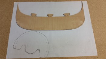
Anyway, I pulled out the second uncut 24″ x 48″ sheet that I still have left over from my original order of 2 sheets, but then found the remaining piece left over from when I cut the original firewall. This piece was plenty big enough from which to cut the 4″ firewall extension.
I marked 4″ up from the bottom edge of the scrap Birch plywood sheet, and then placed my existing firewall in place with the vertical edge aligned flush with new plywood edge & the firewall bottom edge aligned with the 4″ line on the plywood.

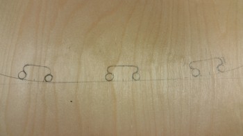
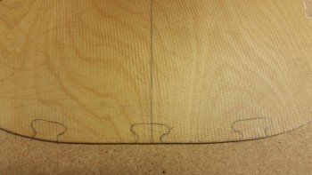
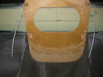
I then traced the bottom of the firewall in relation to the marked 4″ line across the plywood piece, and then again along the very bottom edge of the plywood piece. The latter will be the new bottom edge of the firewall. I then made 3 puzzle piece styled locking tabs to help lock the new 4″ firewall extension in place when it is attached to the bottom of the existing firewall.
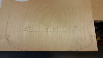
Here’s a closeup of the “puzzle piece” tabs. I grabbed a 27/64″ (.421″) drill bit and traced the bottom edge of it to the side of each puzzle piece tab to mark the drill points that will make up the compound curve of each locking tab side.
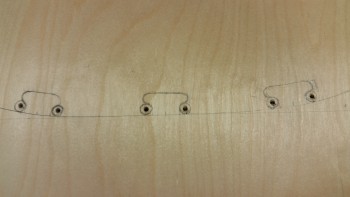
I then drilled a smaller pilot hole for each circle I just marked.
Loaded up the mojamma 27/64″ bit . . .
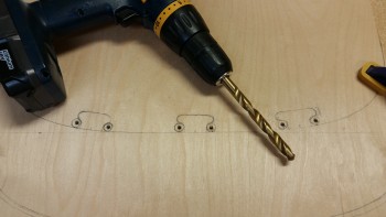
. . . and drilled the holes to make up the compound curved edges of the puzzle piece locking tabs.
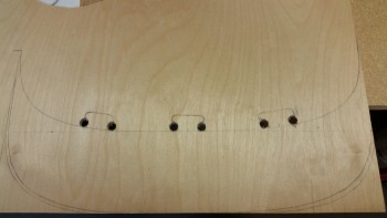
I then used my jig saw to cut out the rest of the 4″ lower firewall extension piece. I would have preferred to have a finer jig saw bit, but since it will all get covered with glass anyway, I wasn’t too concerned about a slightly rougher edge.
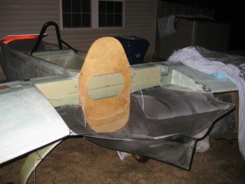
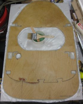
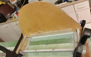
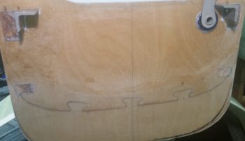
Here’s the new firewall extension piece mocked up along the lower edge of the existing firewall.
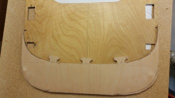
And another shot of it by itself.
•••
3 February 2016 — Today I marked up the lower firewall to cut for adding the extension.
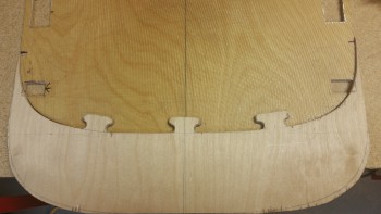
I then marked the lower firewall to cut the matching “puzzle piece” interfaces with the wood extension piece.
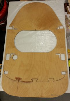
After cutting the “puzzle piece” notches in the lower firewall, I then test fitted the firewall extension.
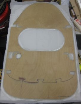
I then floxed the firewall extension piece to the lower firewall & glassed with 1 ply of BID.
And peel plied the lower firewall extension addition.
•••
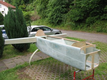
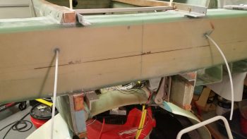
5 February 2016 — Today I mounted the extended firewall to the aft fuselage early on in the day.
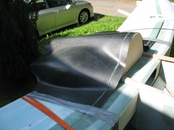
Here’s a shot showing approximately what the new profile of the aft fuselage will be when the plane is finished. Of course this is upside down, but clearly the width & bulk of the fuselage will be extended aft to create more of a “boat” shape vs. the traditional swoop of the old P-51 style inlet. In short, my Long-EZ will have the same profile as one that has a NACA scoop intake.
That being said, I will have a 3″ round air scoop, somewhat like James Redmon has on his Berkut 13, that will run from aft of the landing brake and slowly meld into the bottom hell hole area so that it should (still in design phase) dive aft into the firewall and flow into the lower cowling skin. Thus, I guess my EZ will look a tad different than all the NACA-scooped EZs.
•••
21 September 2016 — Tonight I finally got that lower cowling mounted so that I could mark up the firewall for trim.
I had to lean way over into the cowling in order to mark the lower line without disturbing the taped-in-place cowling.
I took this shot just to get an idea of what the bottom profile of the plane will look like.
•••
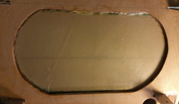
28 October 2016 — I backtracked to finish a step in Chapter 4 that is about 5 years late in the making: glassing the front face of the firewall with 1 ply of BID. I had held off initially to wait to see if I needed to added any screws, etc. and just never got around to glassing it.
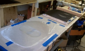
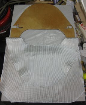
I used the firewall as a template to mark & cut the BID at a 45° bias.
I then took the firewall outside and sanded it down with a DA sander to prep it for glass.
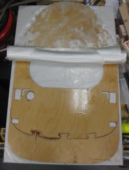
I set the BID in place on the firewall then pulled it down and wet out just the top side of the firewall face.
Then I set the BID in place on the top side of the firewall, rolled the BID up towards the top and wetted out the bottom of the firewall face with epoxy.
I then wet out the entire BID on the firewall face.
With the BID wetted out on the face of the firewall, I then peel plied the entire layup.
•••
29 October 2016 — I spent a good half hour between removing the peel ply off the firewall front face 1-ply BID layup and then razor trimming the edges. The firewall looks good and is very close to getting mounted. I do have to do some minor sanding along the edges and a couple places on the front face, and quite a bit on the aft side since I didn’t peel ply it for some odd reason (that was back in 2011, so my memory is foggy on why I didn’t peel ply it! . . . )
•••
28 August 2017 — Today, after reviewing a bunch of pics I took of Marco’s firewall and engine compartment, and researching a bit while looking at some other folks’ firewalls, I then reworked the component diagram I have for my firewall. May seem a bit ahead of the game, but if all goes right I will be mounting the firewall to the fuselage for good here in the next few weeks, and I wanted to figure out internal hell hole (aka “firewall forward”) cable & wiring runs, oil heat line configuration, and component placement. Obviously, figuring out a close estimate of where all my firewall transitions will be on the engine side of the firewall will drive the placement requirements on the hellhole side of the firewall.
•••
4 February 2018 — Today I started off by performing some slight of hand that, quite honestly, at this point & time I don’t remember quite how I found this out. I do remember the originator of this idea gave some specifics, which was basically purchasing a stainless steel bathtub handle that includes some requisite flanges that magically allows it to be turned into a firewall pass-thru for electrical wiring.
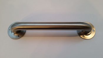
The trick is rather simple, extricate the amount of tube and flange from the handle grip section, and Voila, you’ve got yourself a mountable stainless steel firewall pass-thru with approximately 1.1″ ID.
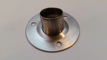
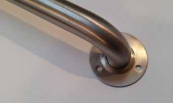 And here it is after I performed my magic (with a Dremel Tool cutoff wheel).
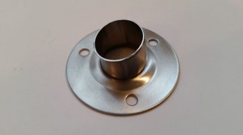 And another shot. As you can see, I wanted just enough were I could mount a length of fire sleeve around the outside of the tube and secure it with a hose clamp.
•••
30 March 2018 — Before doing the final mount of my firewall today, I snapped a couple final official shots of my bird sans permanently mounted firewall….

The pics above were actually taken after my initial task of cutting and micro’ing into place a small piece of foam filler on the lower aft end of the left fuselage sidewall. Again, since my fuselage is much more football shaped than a stock Long-EZ, it really places each end sidewall mating surface –that would normally mount near-perpendicular to the front face of the firewall– at a more significantly oblique angle to the firewall face. To account for these odd mounting angles, it requires some more judicious filling with foam, flox, and micro.
It took me yet still another hour+ to get the prep finished before I started mixing my first batch of epoxy. I then set about mixing a boatload of flox to get all the interfacing surfaces covered before clamping the firewall into place.
It took a bit, but once I got the firewall set in position I then laid up my prepregged 2-ply 2″ wide BID tapes (boy, it’s been a while since I dealt with BID tapes!), starting on the top CS Spar to firewall junction across the spar in-between the top engine extrusions. I peel plied this layup since I would be in the D-Deck/GIB headrest compartment a fair bit and decided to forgo having my hands ripped to shreds with wonderful invisible glass spikes.
I then laid up the 2-ply 2″ prepregged BID tapes on the bottom side CS Spar to firewall corner, and both the left and right corners. As you can see, before I did any of the BID tape layups I added a flox fillet to each corner.
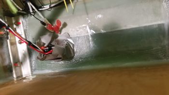
A bit wider angle shot of the lower CS Spar edge 2-ply BID tape to the front side firewall.
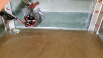
Here are the corner BID tapes. After I reviewed these pics I went back in and cleared out a couple of those air bubbles.
I then spent well over an hour tweaking and cleaning up the flox gunk from all over the firewall. All in all, a step that I thought would take 2-3 hours at most [I mean, com’n, we’re talking 4 BID tapes here… ] ended up taking about 6 hours!
As you can see, I used a cargo strap to pull the lower firewall in towards the fuselage to align the firewall top to bottom. In actuality, the bottom is pulled closer to the fuselage by about 0.050″ to 0.060″ (<1/16″) to compress it tighter with the lower aft fuselage sides. This action squeezed out a decent amount more of flox so helped minimize weight just a tad more. Plus, once all the lower cowling attach joggles are glassed in, it will be near impossible to tell that the lower firewall is set/angled forward less than 1/16″ of an inch more than the upper firewall.
And here she is: the attached firewall! Woo-hoo!
•••
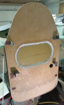
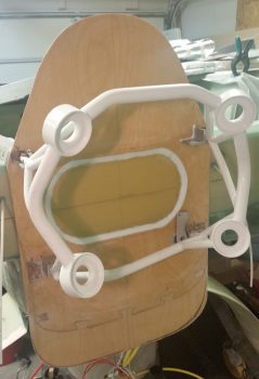
31 March 2018 — I started off today making a paper template that will allow me to fill in the oval cutout of the firewall with 1 ply of Kevlar to add a bit physical and heat protection –as well as some noise dampening properties– to the bare shear web. To be clear, the CS Spar will be bare during the build then covered with Fiberfrax and 6061 firewall covering (yes, regarding using aluminum as the firewall covering I’ll reiterate that I ascribe to Burt’s design that uses the aluminum as the structural covering for the firewall that also serves to protect the Fiberfrax… which is the REAL fire barrier in this configuration).
I then used my oval firewall template to mark and cut out the ply of Kevlar.
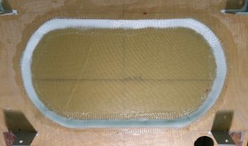
I prepregged the Kevlar ply then laid it up on the bare CS Spar shear web, peeking out of the oval cutout in the firewall. I used fast hardener so that it would cure as quickly as possible.
I then peel plied the Kevlar ply layup and let it cure well into its green state.
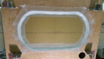
With the Kevlar layup still slightly tacky but cured enough to let me carefully pull of the peel ply, I then created a fairly dry flocro fillet (about 70% micro/30% flox) around the edge to transition the 1/4″ plywood edge down to the surface of the CS Spar for a good glass flow. I then laid up my prepregged 1-py 1.5″ wide BID tapes around the perimeter, covering the flocro fillet and overlapping onto both firewall face and the ply of Kevlar I had just laid up. [Note that in this pic and a couple below you can see where I flocro-filled the gaps in the “L”-shaped firewall openings around each engine mount extrusion].
Here’s a full firewall view shot of these layups.
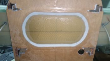
To both prep the surface for better adhesion to the 3M high temp RTV that will secure the Fiberfrax in place to the firewall, and to remove the nasty, jagged sharks teeth of death that await unsuspecting fingers and forearms, I peel plied the perimeter BID layups.
A few hours later I pulled the peel and was somewhat pleased with the results. I say “somewhat” because the actual layups are fine, but I think I allowed myself to fall a little prey to groupthink here in that I have seen this style firewall layup done on a number of Long-EZs. However, with hindsight being 20/20, if I could go back and do it again, I think I would simple bevel the firewall plywood with a router to provide a simple transition from the firewall surface to the CS Spar. Although I used somewhere between a paste to dry flocro, it still added more weight than I would have preferred, even though I tried to balance weight vs strength. Oh, well. It was done so I pressed on!
•••
2 April 2018 — Today I cleaned up the lower firewall by hacking off the lower longeron nubs that were sticking out of the firewall.
And then sanded them down so they looked like this:
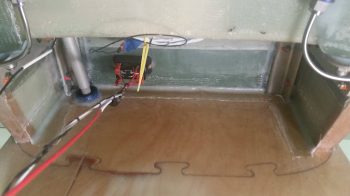
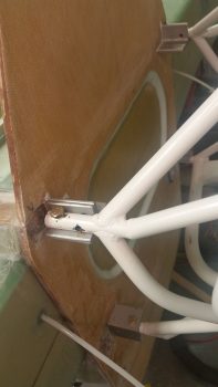
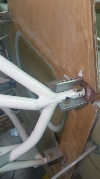
I then sanded the edges of the interior Hell Hole BID tape layups, and worked on the bottom longeron to firewall corners a fair bit. As you can see, the SD-8 Alternator relay and aileron control tube are looking ok.
I then did a quick test install of the engine mount on the firewall to ensure my efforts were all for a good cause! Actually, the quick test fit came after a half hour of me chamfering all the engine mount bolt holes on the firewall extrusions, then taking a file to the engine mount to clean up the rough edges on the bolt holes.
The engine mount fit well, although I noticed that the lower right engine mount stub was gapped vertically with the lower right extrusion about 0.030″, and the left the same at about 0.020″. I think there’s enough flex in all this that they can be cinched up fine without any undo stress, but it is interesting how these things appear after the fact.
Here’s a shot of the left and right side test-fitted engine mount.
•••