
Chapter 13 – Nose Hatch Hinges & Latch
This page covers the planning, design and installation of the nose hatch hinges and the latch assembly.
28 June 2018 — Today I started out in pretty much pure research mode since I felt that before I could glass in the interior skin of the nose hatch I needed to have a good understanding of what was getting attached to it both hinge and latch wise.
After checking out a myriad of other builders’ blogs, etc, I headed down to the shop with some ideas to test out. One idea in particular is that Nate Mullins is using a spring-loaded hinge that was designed for a cowling oil dipstick access door, but he repurposed it for the nose hatch.
I have one of those hinges that I bought for the cowling oil dipstick access door, but for the nose hatch I liked the idea of having a narrow depth on the hinge and getting it out of the way. I tested it out a bit and realized that there was just no way it was going to work since my configuration is much different at the front of the nose hatch than what Nate has…. so I went back to the traditional hatch door hinge that we tend to use a lot in the canard world. I have a template that I traced from a hinge template that Beagle sent me, that –like the nose hatch– is actually for a Berkut. This hinge design is significantly smaller than the ones the Cozy Girrrls sell, which I have BTW and will be using on the aft nose cover.
After messing around with the configuration and testing different scaled sizes of this hinge, I finally came to the conclusion that the hinge pivot point must be as far forward as I can get it in the battery compartment, and the best size is the original size that I have from the template. Moreover, with that knowledge in hand I now know that I will have to do some major rework on my interior top nose structure to get the hinges mounted in there, so I’m going to let ideas of just how to install the hinge pivot points germinate in my brain a bit.
•••
22 April 2020 — Today I started on a Long-EZ related project that I began messing around with last night and a bit this morning:
“J” hinges
I have a set of these hinges that I picked up from the Cozy Girrrls and they are very nicely made. The pair I have will work fine for securing the front of the aft nose cover, allowing me to open up the back half of the nose like an MG sports car.
However, I need a pair of these “J” hinges (what I call them for my lack of knowing their true nomenclature!) for the front nose hatch, just a heck of a lot smaller than the ones I currently have on hand.
Having recently re-covered some instructional info on how to import a diagram into Fusion 360 CAD, I decided since it was fresh in my mind to finally get to using the Cozy Girrrl J hinges as a template in creating smaller versions for the front nose hatch.
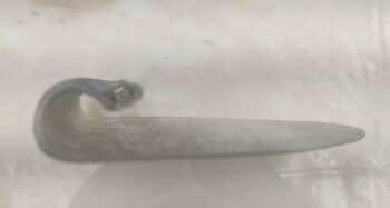
As you can see below, after I modeled up the J hinge I decided to simply print one out on my 3D printer.
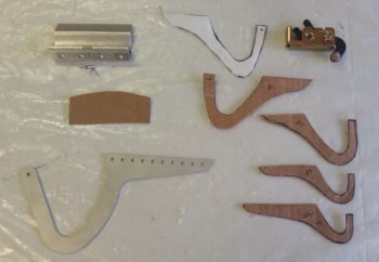
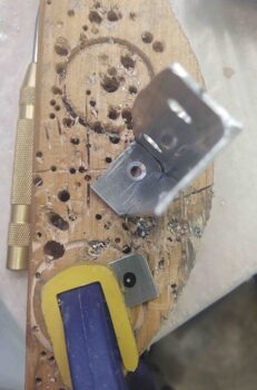
Here’s the new full size 3D printed hinge next to the real aluminum one. Below that are 40% versions of the larger standard sized hinges. I’ll use the small ones as a starting point to find the best size hinges to use on the front nose hatch (the small hinge on the right had some clear issues during the 3D printing process, but it will work fine as a size template).

I took this pic below to show my size comparison between the CAD model hinge and the real one, which is underneath this 3D printed hinge.
•••
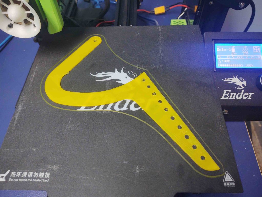
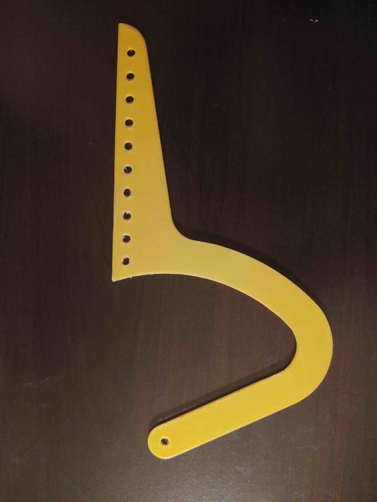
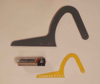
14 September 2020 — Today, after getting my 3D printer back online, I did my first real part (for fit-testing) in PETG: the resized front nose hatch hinge. After a few slicer tweaks it turned out great. A much better size than my original smaller one (yellow). The AA battery is simply for size comparison.
•••
25 September 2020 — Today I started on the nose… specifically the nose hatch hinge assembly. I’ve played around with different configurations on how to mount it, and one really viable option now is to mount some flanged bearings into the hinges to then mount into the nose. The current hinge (on the left, below) was set up to simply use a 3/16″ bolt through it, but that configuration has some clearance issues.
The bearings cleared up the clearance issues, and in the long run is the simpler solution, so I widened the hinges to nearly an inch wide to allow for a bigger diameter hole to seat the bearing into.
It actually took me a little bit to tweak this in Fusion 360. I had just kicked off the 3D print of the new hinges, was making sure the first few layers went down well, and then was getting ready to head back out to the shop to start working the bracket side of the nose hatch hinges when my little buddy called me. She’s been having a bit of a hard time at school so I took a few-hour break to go hang out with her.
When I returned home, my newly designed hinges were done on the 3D printer bed. To be clear, I’m not crazy about the fatter design, but they will be stronger overall and can of course take the 1/2″ OD bearings. Also, I’ll note that these are test hinges, subject to changes, and the final ones will be aluminum.
•••
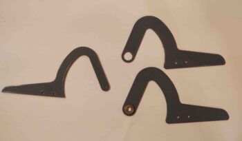
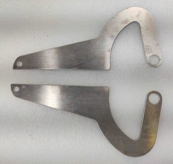
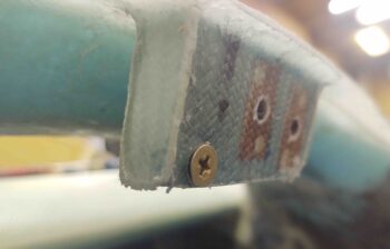
26 September 2020 — I also assessed the hinges and hinge assembly on the front nose hatch. After doing some mental and cardboard mockups on the hinges’ configuration, I determined that the aft tip (right end below) needed to be around 20ºish degrees/1″ higher to interface with the hatch door interior surface at the appropriate angle.
The upper hinge is the one I tweaked the aft attach portion angle. You can tell the difference by focusing on the 2 small holes: parallel with edge on previous version, and at an angle on latest mod.
•••
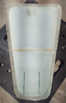
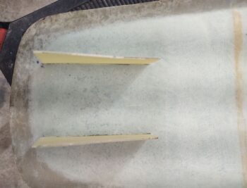
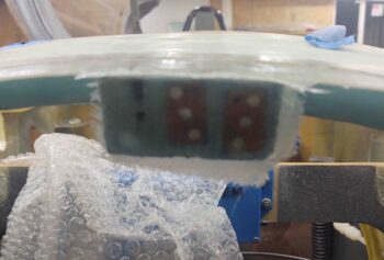
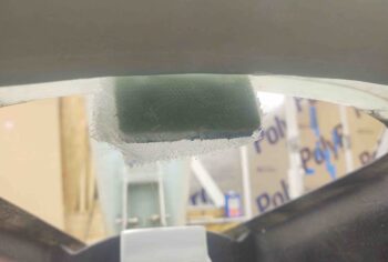
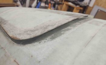
27 September 2020 — Today I started off by marking the edges of the glassed-over block of H250 foam I buried in the front of the nose, right at the top aft side of the furthest forward bulkhead. I placed this block of uber dense foam here to mount the nose hatch door hinge bracket assembly to, although I never had a concrete plan as to exactly how that would look…. until now.
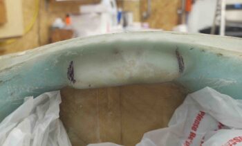
I then used my Fein saw and trimmed about a 1/4″ wide channel –going forward– at each mark.
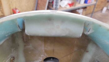
These slots are where the hinge pins will protrude out each side, left and right, of the hinge bracket assembly. Then the hinges will mount inside the slots on each side of the bracket.
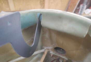
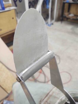
I tested the original hinge configuration and grabbed a shot of it here. As you can see, if I raised up the top mounting edge of the hinge (the front edge is elevated enough to touch the hatch door already) to be parallel with the door line, it would literally protrude through the top of the door.
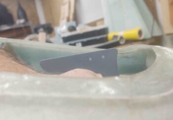
Here we have the new modified hinge with the pivot point in nearly the exact same spot as above, but as you can see the top portion of the hinge that will mount to the door is about parallel with the line of the door…. much better!
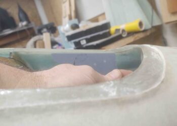
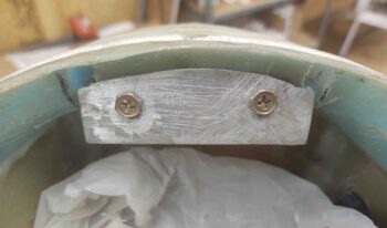
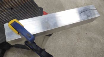
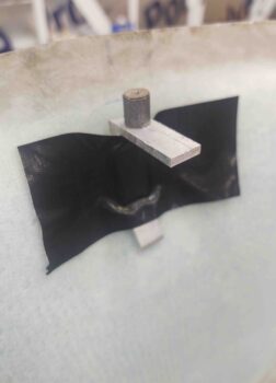
I then trimmed the 1/16″ thick by 1″ x 1″ angled aluminum to serve as the main body for the bracket. My band saw isn’t the most robust so it got a little wavy on the left top edge, but since this will buried under the nose I’ll just file it down a bit and call it good…. function over perfection!
I will note the ends will be capped each with a piece of 1/8″ aluminum that I’ll weld into place. Sticking out of each end will be a 1/4″ long x nearly a 1/4″ in diameter nub that will serve as pivot points (ala “axels”) for the hinges. The hinges will be secured to these nubs either by E-clips or cotter pins.
•••
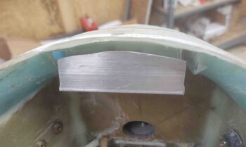
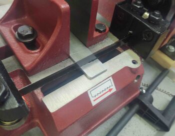
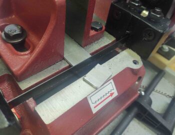
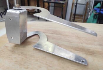
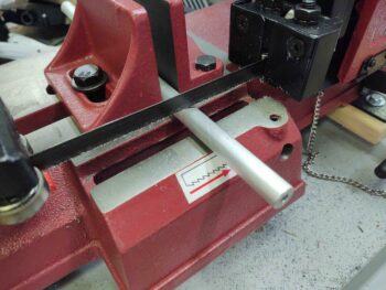
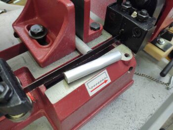
28 September 2020 — I started off today by measuring and then using my horizontal bandsaw to cut a piece off a 1/8″ thick x 1″ bar of 6061 aluminum for an end piece on the nose hatch hinge bracket.
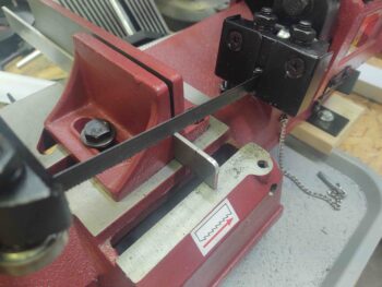
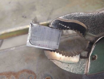
I then cleaned it up and using a big pair of vice grips, clamped it onto the right side of the 1/16″ thick 6061 aluminum angle that will serve as the main nose hatch hinge bracket.
After spending a good half hour re-learning what all the myriad of knobs do on the front of my new TIG welder that I’ve had for almost 6 months, I then got around to testing it out for the first time by hitting the bracket with a quick tack weld in the corner.
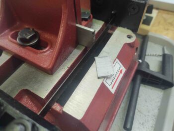
I then reset my vice grip clamp . . .
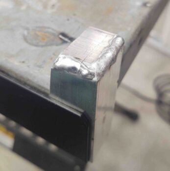
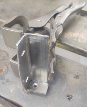
And welded ‘er up. Not great, but not horrible for not having done AC/aluminum welding in over 7 years. In fact, last time I welded aluminum was at the EAA TIG welding course I took in Georgia in early 2013 while deployed to Tampa, FL.
A note that since I don’t have my bench grinder set up yet for sharpening TIG tungsten electrodes, I grabbed a sharpened one that was much bigger than the 1/16″ called for to do this job. That would in part account for the copious amount of filler material on the weld (but more so my rustiness!).
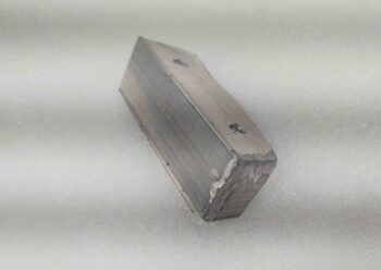
I then ground off the extra aluminum left on the welds. I’ll clean it up much nicer later. With the end plate welded in it allowed to me set the bracket and then press it to the left and know my left-right placement to drill the pilot holes for the screws and the upcoming embedded nutplates.
To ensure alignment between the bolt holes I drilled in the bracket and the nutplate assemblies I made up, I had originally planned to mount the nutplates onto the bracket and then clamp the bracket into place with nutplates secured to it. But I couldn’t see behind the bracket and I could not tell 100% what was going on. I didn’t want a nutplate on one side embedded as it should be and the other side off –but floxed– securing it into the WRONG place!
So I decided to simply flox the individual nutplate assemblies into place and then adjust the hinge bracket mounting holes slightly if required.
•••
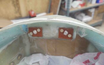
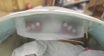
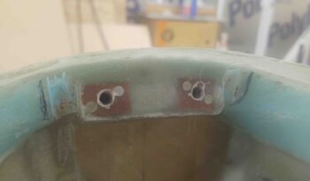
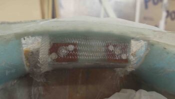
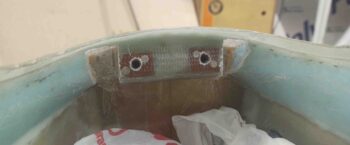
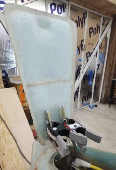
29 September 2020 — My first task in the shop today was to get a 2-ply BID layup over the nose hatch hinge bracket nutplate assemblies that I embedded with flox yesterday. I then peel plied the layup.
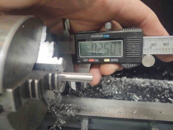
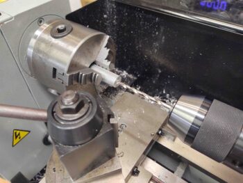
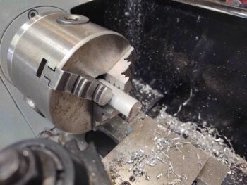
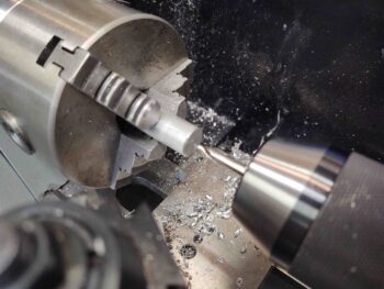
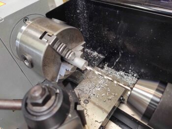
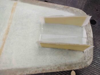
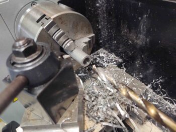
As the layup cured, I got to work on a hollow stainless steel shaft that I ordered from McMaster-Carr and was just delivered mid-morning. I’ll be using the shaft as a sleeve over the screw/bolt coming out of each side of the nose hatch hinge bracket, and for the flanged ball bearing press fitted into each hinge to ride on.
The sleeve OD is right at a 1/4″ (0.250″) . . .
While the ID of the bearing is 6mm, or around 0.235″.
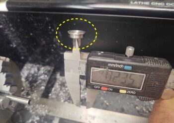
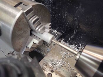
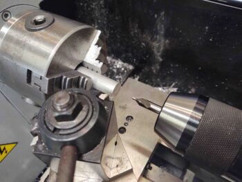
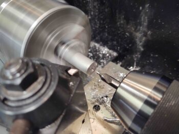
I then used the lathe to take down the SS sleeve OD to just under that of the bearing ID.
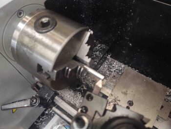
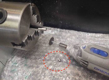
My parting tools suck, especially on stainless steel, so I just marked the cut line and then used the Dremel as I had the sleeve rotating in the lathe chuck.
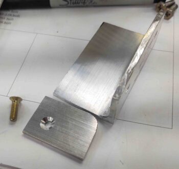
Since the last 3D printed test hinge was right in my sight, I grabbed it to test out the bracket-screw-washer-bearing/hinge-nut setup. Once together, it all worked nicely.
Note the flange of the press-fit bearing (blue arrow).
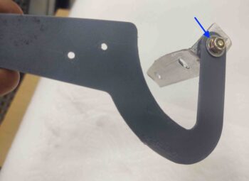
Here’s a shot from the inside of the bracket, with the countersunk #8 screw head showing.
I then cut the 1/8″ x 1″ 6061 bar stock for the other (left) end of the nose hatch hinge bracket.
I then marked the screw hole to match the right side of the hinge bracket (although I forgot to countersink the hole, which is one reason I drilled the hole prior to welding… argh!!).
I then prepped the hinge bracket for welding.
A bit later, after a horrendous welding session, I test mounted the bracket. The inside corners were just being really tough to get any good welds into, totally exacerbated by my lack of practice or any recent TIG work. I simply put too much heat into this aluminum part and actually cracked it as I was trying to bend the slightly heat deformed right side back to vertical.
I then realized that this bracket just became the prototype for proof of concept of my hinge install setup, and that a new thicker (and taller) bracket would need to be constructed (or possibly milled …. hmmmm?).
After loading all my pics I also realized I didn’t get a shot of the finished layup …
•••
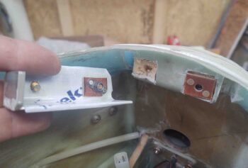
30 September 2020 — Not much done today, but I seated, test-fitted and then marked my prototype nose hatch hinge bracket to assess the gap I need for the hinges on each side. I then marked those and plan to widen them.
•••
1 October 2020 — I started out today with multiple successive cuts just under the front nose hatch lip on each side of the hinge bracket to allow for the hinge and retaining nut to slide into place. Remember, I cracked the right side half off so I can’t test fit a hinge there, but one hinge will do what I need here. Yes, still need to make a new bracket . . .
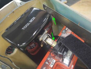
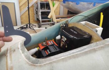
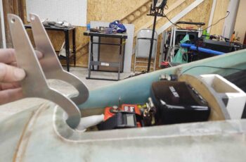
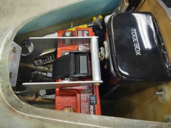
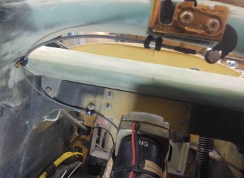
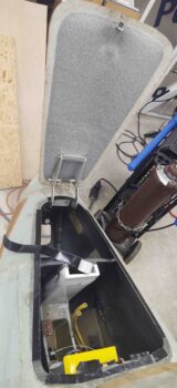
I put the battery back in the nose, because I was focusing mainly on that clearance with the hinge. I quickly realized I needed to go grab my tool box and put it back in place to check that clearance as well with my longer hinge.
To then realize further that I had some issues to resolve. My new longer hinge is over an inch too long for clearing the tool box.
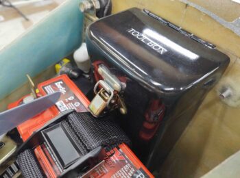
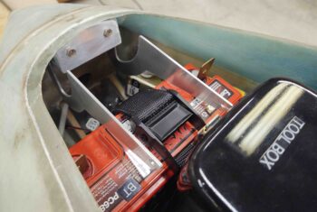
Moreover, I apparently never vetted the tool box’s clasp operation with the rather robust battery securing strap I have around the center of the battery. The clasp arm snags in opening and closing on the battery strap clasp… by about 1/8″.
Solution? You can see the line I made on the tool box clasp to simply trim it down. There’s not a ton of force required on the clasp to open or close it, so I don’t foresee any issues with cutting it a bit shorter.
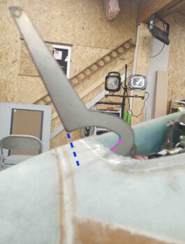
After playing around with the door and setting it where it would be in place aligned with the hinge, I quickly realized I have a hinge alignment issue. I tested it out a little with the older “wrong-angled” hinge and I don’t think it’s due to the new angled hinges, but at this point simply because the “U” part of the hinge is too big.
The gap between the double magenta dashes (bottom trough of “U”) and the front edge of the hatch needs to be reduce to almost nil. Moreover, the height between the front connecting edge of the hinge (top of “U”) at the blue dashed line needs to be minimized quite a bit as well, since with this current configuration the front tip of the hatch door would rest on the top of the nose (not good) versus the front lip of the nose hatch stopping the hinge travel when the door is opened fully, as in this pic.
In addition, I think moving the hinge pivot point as far forward as possible should help mitigate my nose hatch door hinge opening geometry issue.
I think I can say authoritatively I now understand why builders go with either the external CAMLOC/screw or the wire-through-embedded tube methods to secure the hatch door to the nose, because this hinge-solution is turning into quite the cluster.
So knowing I had to go back to a few different drawing boards, I called “Uncle!” for the time being on the nose hatch and went to work on the milling machine reassembly.
•••
4 October 2020 — In addition to cutting out the final instrumental panel, I also plasma cut a new nose hatch door hinge. The size fit is good, but I’m still off on general configuration, as I have been on all these hinges. There is clearly a configuration trick that I am missing, so I’m going to have to do some remedial research and possibly call around for some help from folks who have done this.
Again, the primary issue is getting the hinges configured so that when the hatch door is open, the door front lip IS NOT resting on the top forward surface of the nose.
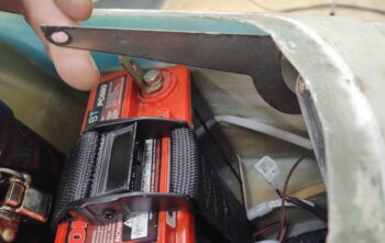
And although it’s hard to tell, I also trimmed the length of the tool box locking latch lever to allow it to clear the (now) secured battery strap.
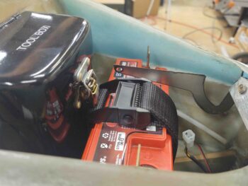
Here we have both the new (shorter) nose hatch hinge in the open position and the tool box –with its now shorter trimmed latch handle– also open, the latter now being able to be manipulated with the battery strap & buckle secured in place.
•••
5 October 2020 — Today I started off with some fairly in-depth research on how to install the nose hatch door “J” hinges in a manner and configuration where they will simply work.
So I discussed hinge configurations back and forth some with Terry Schubert. In addition, when I found out Terry Lamp and Mike Toomey were down in Chesapeake visiting Marco and Chris Cleaver to help them with their respective condition inspections, I called and spoke with both Terry and Mike.
Terry deferred to Mike, and Mike had some good advice. I think if I have any hope in actually getting these hinges to work, it will be on his word that I should mount the hinge pivot points as high and as forward as feasibly possible.
Thus, towards the end of the evening I Dremeled out as far forward as I could in the channels I’ve created on each side of the nose hatch hinge bracket.
•••
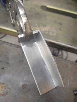
6 October 2020 — Out in the shop I grabbed a piece of angle 6061 aluminum and got to work on the new nose hatch hinge bracket… clamping it down for cutting.
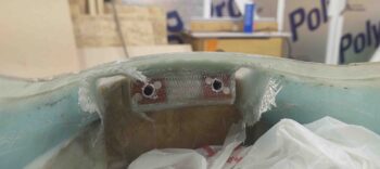
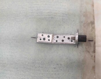
Here we have the new nose hatch hinge bracket after cutting it out of the angled aluminum extrusion. As you can see I transferred the bolt mounting hole positions from the old bracket to the new one and bolted the new one into place.
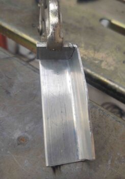
I then got to work on the sides. Here we have the left side wall of the nose hatch hinge bracket shaped, drilled and ready to be welded into place.
Welding 1/8″ sides to the same 1/8″ thick bracket front wall and bottom went much smoother this time around. These pics are of the welded bracket without any clean-up of the welds.
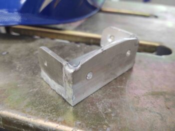
Again: much, much better than the initial bracket (I will do some clean-up on the welds, but nice not to have to test fit it!).
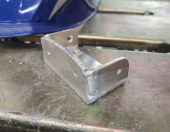
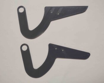
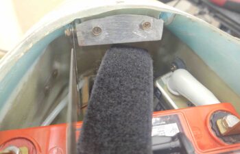
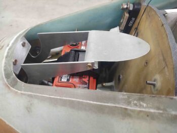
I then bolted the freshly welded nose hatch hinge bracket into place, with a couple of test hinges attached.
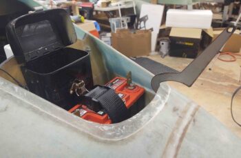
I thought I’d post a better shot of the trimmed tool box latch handle… I even turned the battery securing belt around to see if it made any difference in clearance, which it didn’t.
With the hinges mounted much further forward (as per Mike Toomey’s recommendation), you can see that the last test hinge that I cut doesn’t even clear the hatch’s front lip.
One of the original 3D-printed test hinges now looks much better in its hinge geometry, although the alignment with the door bottom surface is still off.
I collected notes on some tweaks I needed to make for the final (hopefully) hinge configurations and updated my Fusion 360 CAD drawing. Fusion 360 (Autodesk) has changed its free CAD software version so when I went to cut out the final hinges on the plasma cutting table I got an error. When I looked up the error on the Langmuir Systems plasma cutting forum I saw that a number of Fusion 360 users are getting the same error… so I, like thousands of hobbyists around the world, have some decisions to make [btw, Marco and I discussed this issue a fair bit last week… I didn’t realize it would effect my plasma cutting table ops].
•••
7 October 2020 — I started off today by adding another ply of BID to the face and underside of the block of H250 foam which makes up the sub-structure and holds the securing nutplate assemblies for the nose hatch hinge bracket. Unlike the previous 2 plies of BID that I laid up to secure the nutplate assemblies, this ply overlaps onto the underside of the hatch lip and on the underside of the H250 foam protrusion (which already had glass on the bottom side).
Since this hinge bracket sub-structure will be hidden primarily by the hinge bracket, I only peel plied the strip just under the hatch lip.
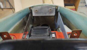
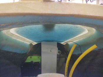
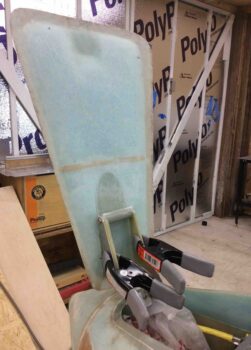
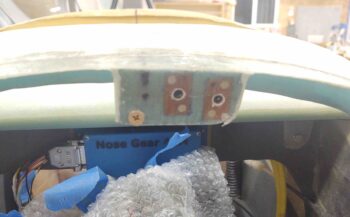
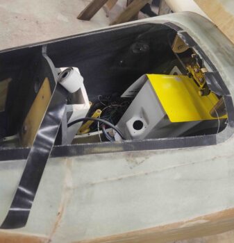
With the aft nose/avionics cover off I took this interesting shot of the forward nose hatch from inside the nose…. I think it looks pretty cool! (can you see Napster peaking out??)
Speaking of nose hatch, here’s the cleaned up 1-ply BID layup from before. It was still just a very tad bit soft, so I’ll sand the edges after it’s cured a good 12 hours more.
•••
8 October 2020 — I did a bit more research on my CAD options since, as I explained. my plasma table was currently out of commission with the changes AutoDesk made to the rapid movements in post processing CAD files for machining, plasma cutting, etc. I thought long and hard about this both last night and up until this afternoon, and figured I couldn’t afford to do the proverbial switching horses mid-stream, so I relented to what is in my opinion akin to extortion and purchased a 1-year license for Fusion 360 CAD. There’s simply too much I need to get done as quick as possible between plasma cutting, milling and lathing, that I simply cannot be non-operational with any of the machines I have.
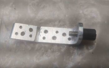
Within minutes of pulling the trigger on my new and improved Fusion 360 CAD (Wrong! I essentially bought back rapids) I was able to use my plasma cutting table again. With that, I cut my latest –and very hopefully final– set of hinges out of the same 0.090″ 6061 aluminum that the instrument panel was cut from. Thus, I’m “proud” to present to you my very costly nose hatch hinges! (yes, I’m being particularly facetious . . . ).
I then took about 20 minutes to clean up the welds a bit on the nose hatch hinge bracket and attached the 6061 hinges to the bracket.
I’m cautiously optimistic and very hopeful that these guys are the ones…. they fit great and the geometry looks very good so far (again, thanks to Mike Toomey for his advice on these crazy nose hinges).
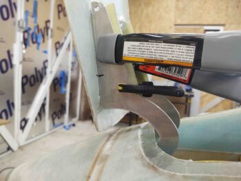
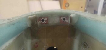
Here’s a shot of the installed nose hatch hinge bracket with the nose hatch hinges installed.
•••
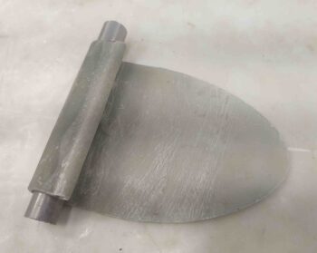
9 October 2020 — Today I started out by getting some epoxy/layup work done out of the gate so it would cure as I did a bit of machining.
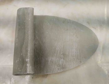
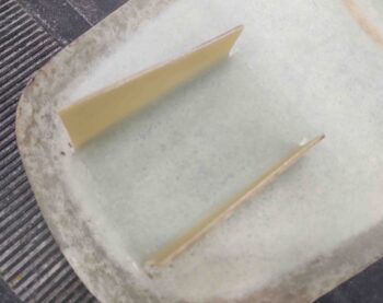
First up is what will be a glass tab, or catch if you will, that will simply be a semicircular “C” shape on the underside of the nose hatch door with the opening facing aft. It will snap into place on a simple 1/2″ diameter 6061 crossbar bolted in between the tips of each hinge. Add an aircraft locking pin between an added underside flange on the nose door and each hinge to make it so that the nose hatch door will be removable… to make the remainder of the build easier and for when a lot of work needs to be done in the nose hatch area and the door is simply getting in the way.
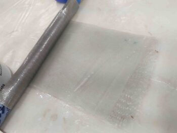
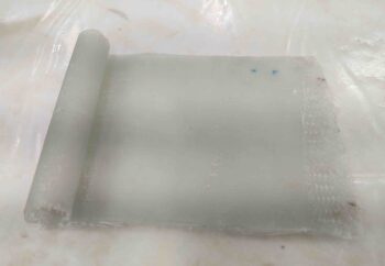
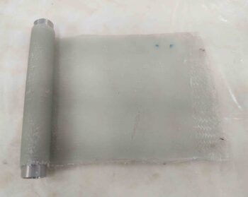
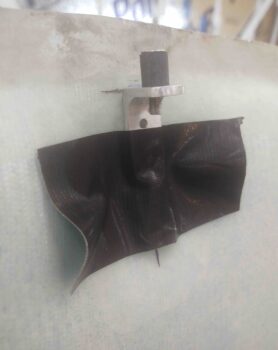
I used a different 1/2″ tube than the one I was machining on the lathe as the mold, and simply laid up about a 4×4 inch ply of BID, a middle ply of UNI, and another ply of BID with peel ply on both sides. I then wrapped one end around the 1/2″ tube and duct taped it into place. I then had to set a couple of objects on each side to keep it from unrolling.
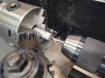
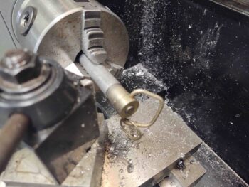
I then rounded up a spare 1/2″ 6061 rod. I was thinking about re-using my 1/2″ elevator control tube with the aluminum Heim end-caps at the end for my bolted-in hinge crossbar, but with the design of my hinge door tab it will wrap around the bar and thus rivets are out since they would require the tab to be much narrower to avoid the rivets on each end. If I simply drilled a hole all the way through this less-than-3″-wide solid bar it would be very reasonably close in weight.
I started by facing (cleaning up) one end with a very slight bevel on the edge to “break the edge” and avoid any more cut fingers (I have a healing nice big gash on my thumb from a machined edge that I grabbed hold of . . .). I center drilled the end to then use a #21 drill bit to drill over 1-1/2″ down the center of the rod.
From there I simply threaded the drilled hole out with a 10-28 tap. Voila! Side 1 complete.
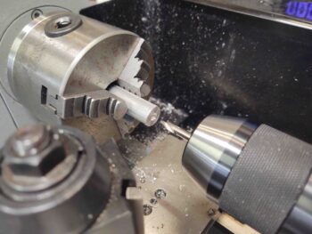
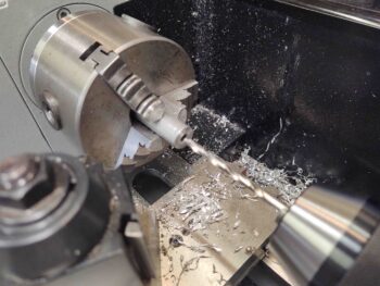
The hinge crossbar needs to be 2.9″ long, so I cut the rod at 2.95″ on my horizontal bandsaw.
I chucked it up with the unfinished end facing out (of course) and did the same thing as before: facing (although with the lighting [lesson learned] I noted at the very end that I hadn’t faced it all the way and had to redo it), bevel, center drill, #21 drilling (end-to-end), and 10-28 thread tapping.
Here’s a closer look at one of the finished ends.
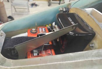
I then grabbed a couple of short 10-28 bolts off the workbench and installed the freshly made crossbar. Fits a treat!
Another shot, showing clearance with the tool box. It just barely touches the tool box latch, but then again it won’t sit this low when mounted to the the underside of the nose hatch door. It will be a couple of inches higher (towards the camera) and completely clear of the tool box latch.
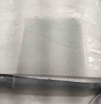
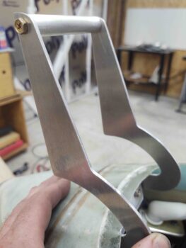
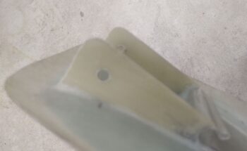
I then removed the 1/2″ tube and the peel ply from my nose hinge/nose door mounting tab. The diameter is a hair larger than I want (from the tape on the tube) so when I open it up into a “C” shape I’ll need to add a few plies of glass to the inside diameter.
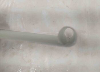
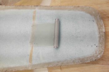
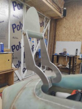
I slid yet another spare 1/2″ tube in place so you can see somewhat how it will look when installed. The first pic as if looking through the top nose hatch door. The second pic from inside the nose hatch door.
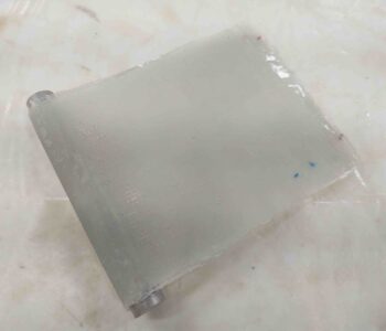
If you’re wondering about the long flat part of my strange contraption here, it is simply to provide an aft side mounting flange to this tab, and a bit of rigidity. Since the underside of the door is curved, I’ll have to fill-in under the circular tab a little bit with micro/flox when it gets installed. I’ll also trim the flat part into more of a rounded “V” or “U” shape to fit in the underside door curve better. After a decent-sized fillet on the front intersecting area with the door (right side in pic), more BID will be added going forward. Each end (top & bottom in pic) will also intersect with the respective vertical flanges that will be installed forward of this tab to interface/mount to each of the hinges.
•••
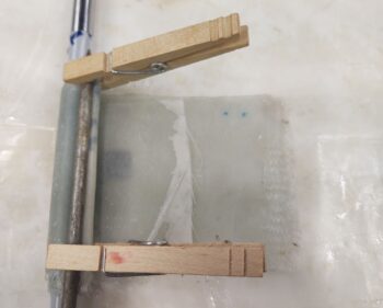
14 October 2020 — I started off today by spending a good hour setting up and adding 3 plies of BID to the nose hatch door attach clip. I cut a drinking straw lengthways and curled it up tighter, taped it and then used that as a lip on the front, top edge of the “C” to have a radiused entry for the hinge assemblies front tube to press against when this clip is being snapped into place. The straw contraption is being held by the clothespins with a big nail to push the glass down behind the straw to make it tight, and give the lip more of a protrusion. You can see the peel ply on all the external surfaces.
I then got busy on the actual nose hatch door. I first spent a good half hour cleaning the old sticky duct tape off the exterior surface of the nose hatch door, and the nose just above the hatch.
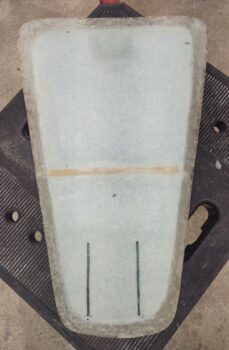
Then, peeking up through the taxi light opening, I set the door in place and then used a few previous dots to slowly dial in the inside lines of each hinge. I didn’t have a way to reach up in there to simply mark the lines, nor did I have a good angle to do so really with an extended pen contraption (I was leaning this way), so I simply took my time (~30 min) and slowly dialed in and marked the lines along the inboard edge of each hinge (left pic, below).
I then used the Fein saw to cut the slots into the interior side of the nose hatch door (right pic, below).
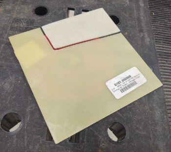
With the slots ready to go, I then cut the first hinge attach tab out of 1/16″ thick G10. I made these tabs a bit taller/deeper than they will most likely end up being, simply to make it as easy as possible when attaching the hinges to these nose hatch door hinge tabs. Of course I’ll trim them to final depth & shape when the hinges are attached.
I then sanded both sides of the G10 nose hatch door hinge tab.
I then cut the second nose hatch door hinge tab and sanded it as well.
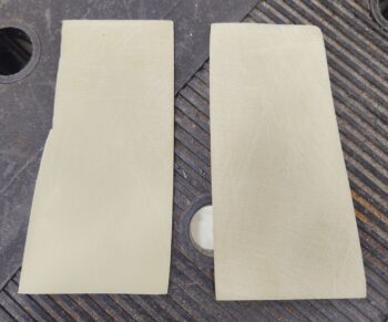
Here we have the pair of nose hatch door hinge tabs test fitted into the nose hatch door. They fit great, so time to mount them.
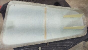
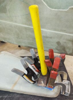
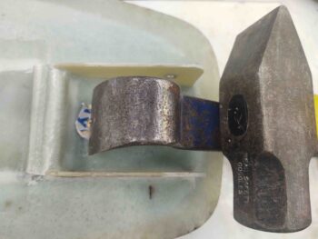
I mixed up some flox and slathered a bunch of it into each slot. I then slid the nose hatch door hinge tabs into place until they bottomed out. I clamped the taped hinge assembly to the hinge tabs to ensure that they were vertical and matched the hinge they would be attached to.
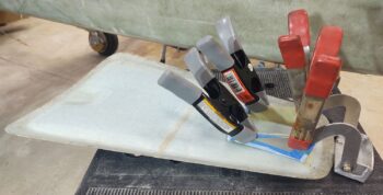
I was heading out to grab a quick bite to eat, so I placed my 5# sledge hammer on top of the hinge tabs to ensure they stayed seated fully in each slot.
I then left these nose hatch door components to cure overnight.
•••
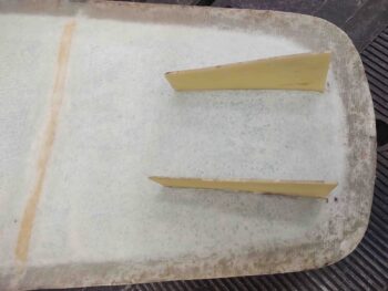
15 October 2020 — I started off today checking my floxed-in-place nose hatch door hinge tabs… they cured nicely and kept their alignment.
With the tabs good I then laid up 2 plies of BID on the interior tab walls overlapping onto the underside face of the nose hatch door. Normally I would use simple BID tapes here, but I went all the way across since I’ll be laying up glass over this and wanted the transition as clean as possible… and at 3″ apart, we’re only talking a 1″ x 4″ added strip.
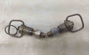
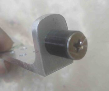
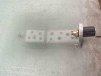
While the layup above cured, I got busy working on the 6061 aluminum “bungs” that I’ll weld to the exterior side of the hinges to keep the nose hatch door securing pins more secure, and more aligned.
What I needed/wanted was essentially a 5/16″ ID tube with a at least 0.090″ wall thickness. So a 1/2″ OD tube with a 5/16″ ID would have worked great… IF I had it on hand. Which I didn’t. Thus my lathe work.
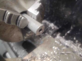
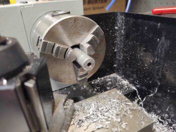
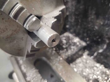
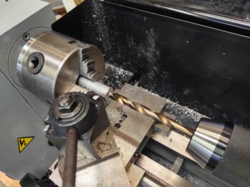
I started out by center drilling a length of 1/2″ dia. 6061 rod.
I then drilled out the center to 5/16″ to a depth of about 1 inch.
I then test fitted my aircraft grade hinge pins.
I didn’t get pics of the remaining process, which was fairly easy. I just lopped off the nubs on the horizontal bandsaw and then faced the end(s) to length, which is 0.322″.
And Voila! Here they are. The fit is nice and tight on the hinge pins. The gap between each bung and the top flange of each pin allows for the combined thickness of the hinge and the hinge tab.
I then cleaned up the nose hatch door hinge crossbar securing clip. I rounded the aft side of the tab part that will get secured to the underside of the nose hatch door.
 Here’s a side view, albeit a bit blurry.
And a shot with a test 1/2″ bar inserted into the clip. This bar is the same diameter as the crossbar at the aft end of the hinges.
I then installed the clip on the hinge crossbar.
It fit well, so I pressed forward with my nose hatch hinge install plan.
By this point the inboard layup on the nose hatch hinge tabs had cured. I pulled the peel ply and cleaned up the overhanging glass.
I then used clamps to position and hold the nose hatch door to the hinges.
And test the operational geometry of the nose hatch door and hinges… which I’m happy to report was excellent! (Again, a big shout out to Mike Toomey for his advice on the hinges!)
I then 5 min glued the hinge clip tab to the underside hatch door surface and the tube part of the clip to the top (as situated here) of the nose door hinge tabs (I had previously cut circular notches to match the OD of the tube part of the clip).
I gave the “5 minute” glue a full hour to cure while I engaged in other shop shenanigans. About every 10 minutes I would cycle the door from open to closed, and vice versa, to ensure that the pivot geometry and alignment was still good.
I then removed the nose hatch door with the hinge crossbar clip secured in place via 5 min glue.
I then did 3 layups: starting first with a ply of BID over the hinge crossbar clip’s aft semi-circular tab.
Next I laid up 1 ply of BID on the outboard right hinge tab (top in pic).
Lastly, I filled in the narrow gap beneath the hinge crossbar clip aft semi-circular tab with a a mixture of wet flocro. Then on the front corner at the junction of the exterior clip tube and the nose hatch door surface I created a fairly large flox fillet. I then glassed in 2 plies of BID from the clip tube near the top and overlapping forward onto the nose hatch door (onto the previous inboard 2-ply layup between the hinge tabs).
I employed the thick heavy nail again to weigh down the peel ply and keep the glass on the top of the clip tube pressed against it.
•••
16 October 2020 — I started off today simply prepping and then laying up 1 ply of BID on the left hinge tab on the nose hatch door.
I did some workshop housekeeping chores, pulled the canard from the rec room in the main house and placed it in the shop, and also did a bit of welding on the instrument panel.
A bit later –after the above layup cured– I got back to work on the nose hatch door install. Here’s a video recapping all the pertinent points.
•••
17 October 2020 — I started off today laying up a ply of BID on each side of the nose hatch hinge bracket mount in the hinge channels. I sanded the channels down first, then dug out some of the blue foam on the sides to then add micro and flox for essentially a flox corner. The ply of BID basically covered the channel outboard walls, the front (bulkhead) part of the channel, the top (nose underside), and then overlapped onto the inboard side of the channel (the protruding hinge bracket mount).
I also did a myriad of measuring, fitting and planning for installing the nose hatch door latch and latch hook.
•••
18 October 2020 — Today my first task was cutting, sanding and cleaning up the 1-ply BID layup in each channel on each side of the nose hatch door hinge bracket mount.
•••
19 October 2020 — I went out to the shop and decided to quickly knock out rounding the corners on the nose hatch door hinge tabs. I marked the radius using an AN970 washer.
And then trimmed the corners with the Fein saw. I then hit each corner with the sanding block and called this task good.
•••
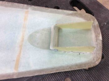
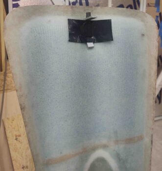
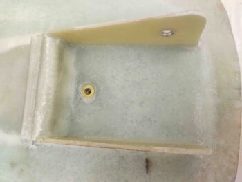
21 October 2020 — I then got back to work on the nose. I made up a test nose hatch door latch striker and mount to dial in the nose hatch door latch. I simply used Gorilla duct tape to hold it temporarily in place.
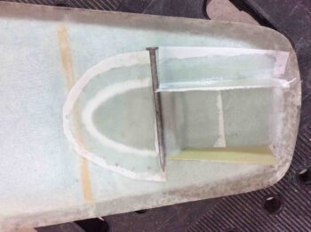
After a few iterations of finding the correct interface, height, alignment, etc. between the striker and the latch, I made up a couple phenolic nutplate assemblies with K1000-3 nutplates and floxed them into a 3/8″ piece of scrap Devinycell foam to make up the nose hatch latch mounting plate.
About an hour later I filled the nutplate threads with Saran wrap, made a 5/16″ hole in the lower right (left, looking at pic) for a flox hardpoint [for cable-securing adel clamp], and then 5-min glued (+ flox) the top edge of the mounting plate to the underside aft lip of the nose hatch.
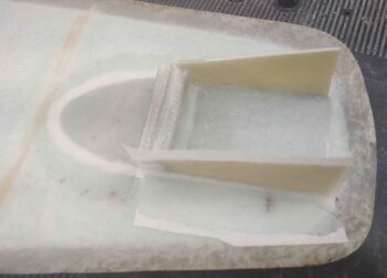
When the 5-min glue was nice and cured, I then laid up 2 plies of BID on the front face . . . (sorry for the fuzzy pic)
And 3 plies of BID on the aft face.
Here’s my attempt at getting a shot to show the black marks on the latch mounting plate with the nose centerline… at least the pic of the latch mounting plate is clear here.

And with that, I closed up shop to the let these layups cure overnight.
•••
22 October 2020 — I started out today laying up a few plies of glass along each side edge of the nose hatch latch mounting plate (pic below) to add a bit of strength to it.
A bit later my glassed nose latch mounting plate was cured, so I trimmed and cleaned up the layups. I also cleaned out the holes in the nutplates and drilled a #10 hole in the flox hardpoint for the adel clamp screw.
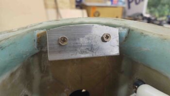
Here’s a shot from the front with the nose hatch latch mounting plate ready for action…
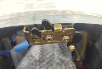
I then mounted the nose hatch latch. Here it is in the close/locked position.
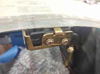
And here we have it in the open/unlocked position.
I was ready to move forward with floxing and glassing my striker plate onto the nose hatch door, but the material I was going to use for the bracket just wasn’t up to snuff (I glassed a hefty 9-ply angle bracket) compared to my test/mockup bracket I’ve been using to dial in the latch… however, in my haste I drilled the hole off center in the test striker bracket.
That alone isn’t causing all the issues, but it’s leading to other alignment/mounting issues so I need to either weld the hole in and re-drill, or cut a new angle bracket for the striker.
However, I did do a good amount of testing on the striker configuration and I’m pleased with how this latch setup will function.
With my night cut short due to a change in striker plans (it was too late to fire up cutting saws, etc.), I came back in the house and spent nearly an hour updating my electrical system wiring diagrams in CAD.
•••
23 October 2020 — Today I got to work making up a new nose hatch door striker bracket. Actually I tried filling in the hole with a weld on the old test one… but clearly my aluminum welding is not up to snuff because even though I followed the amps-required reference card, I didn’t even get to 2 seconds before the tab was obliterated… I digress.
Here’s the new bracket with a new straight striker. I realized not only was the hole off-center on the previous one, but the first striker tube was slightly canted to one side. Noting that, I cleaned the ends of this one up on the lathe.
And then spent a good 15 minutes testing it out. All looked good, and centerline seemed the place to be.
I then did final preps for glass, floxed it in place and laid up 5 plies of glass over it to secure it to the inside nose hatch door.
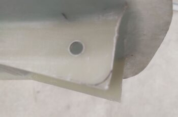
I had a bit of epoxy left over from another layup, so I installed a RivNut on the nose hatch door in the vicinity of the hinges to attach the aircraft hinge pins to so they wouldn’t be loose when not securing the hinges to the nose hatch door.
I floxed the RivNut in place in the hole I drilled, and then weighed it down with my 5-pound sledge hammer. I then took off to go hang out with my friends for a bit.
Upon returning back to the shop, I cleaned up the flox around the RivNut… which turned out nice.
I also pulled the peel ply and cleaned up the nose hatch door striker bracket layup.
I’ll explain it more in a video where I can show the geometry, but the short story is that I ended up putting the previous (yes, canted) striker back in place to obtain a better alignment. Yes, I did test the new straight one out around a dozen times, but the previous striker just aligns better when the nose hatch locks into place…. these builds can have some strange twists to them. So in this case, crooked is straight!
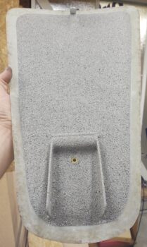
I then taped off the edge of the interior nose hatch door, the striker tab and the outboard hinge tabs and primed, then painted the door.
•••
24 October 2020 — My first task today was to run out to the shop and shoot the nose hatch door interior surface with a couple coats of clear.
A number of hours later, after it had seemingly cured, I started to tape off the painted area to hit the edge with some rubberized black paint to provide a minimal sealing effect. Well, when I went to readjust the painters tape it ripped up a decent chunk of my good paint.
Back to square one. I taped off the edge again and spritzed the damaged areas with enough paint to hide the damage. [Way later in the evening I hit it with 2 more coats of clear and set it aside to get a really good cure].
•••
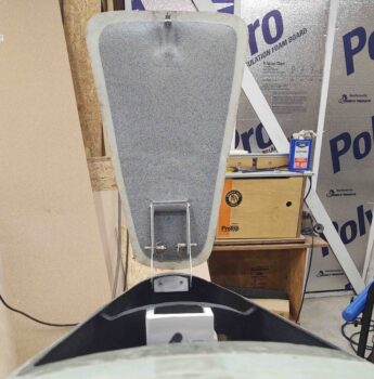
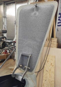
25 October 2020 — With the nose hatch door paint good and the clear coat on and intact, I mounted the door to the hinges… here’s a couple shots.
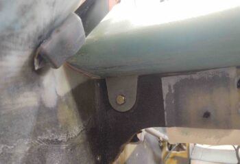
I then got busy installing a click bond with 3-plies of glass over it on the front face of F22, and a RivNut on the upper side wall (held in place by clamp) to allow me to mount Adel clamps when routing the nose hatch door latch cable.
I then carefully trimmed the nose hatch door latch pull cable to length with my Dremel tool…
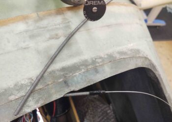
. . . routed the cable and terminated it at the door hatch latch arm.
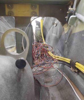
This is a view of the nose hatch latch pull handle. Pardon the bundle of wires behind the cable pull handle… that’s why I have wire labels and electrical diagrams! ha!
Here’s the nose hatch door and nose centerline (top) marks. The nose hatch door is latching about 1/16th to the right (left in pic). Doesn’t seem like much, but considering it skews how the nose hatch door sits in the “pocket” created by the lip and surrounding flange, I’m going to dial it in to move it back to centerline.
Like I mentioned before, the nice thing about this style of latch is that when you “pop the lid” it gives you a nice raised hatch door to grab ahold of to open it up.
•••
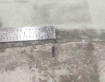
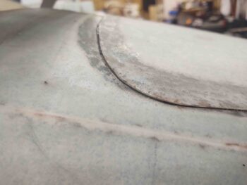
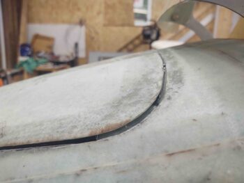
6 November 2020 — I took a good half hour to test out my 1/32″ flat peel-n-stick rubber seal I got from McMaster-Carr. I checked the Gorilla duct tape and found that 2 layers of that came out to about 0.031, the same as my seal tape. So I tacked it in place and tried it out a number of times….
Seems like the 1/32″ will do just fine. The front hatch door still locks and opens fine.
And whatever gap it creates I can fix with an extra ply or two of glass (and then some micro) on the surrounding nose area around the nose hatch.
•••