
Chapter 14/19 – Wing Bolt Mod
This page covers semi-permanently installing the wing bolts into the CS Spar facing aft to make mounting and removing the wings a much easier process.
10 November 2020 — Today I removed the canopy and roll bar in prep for the upcoming strake build.
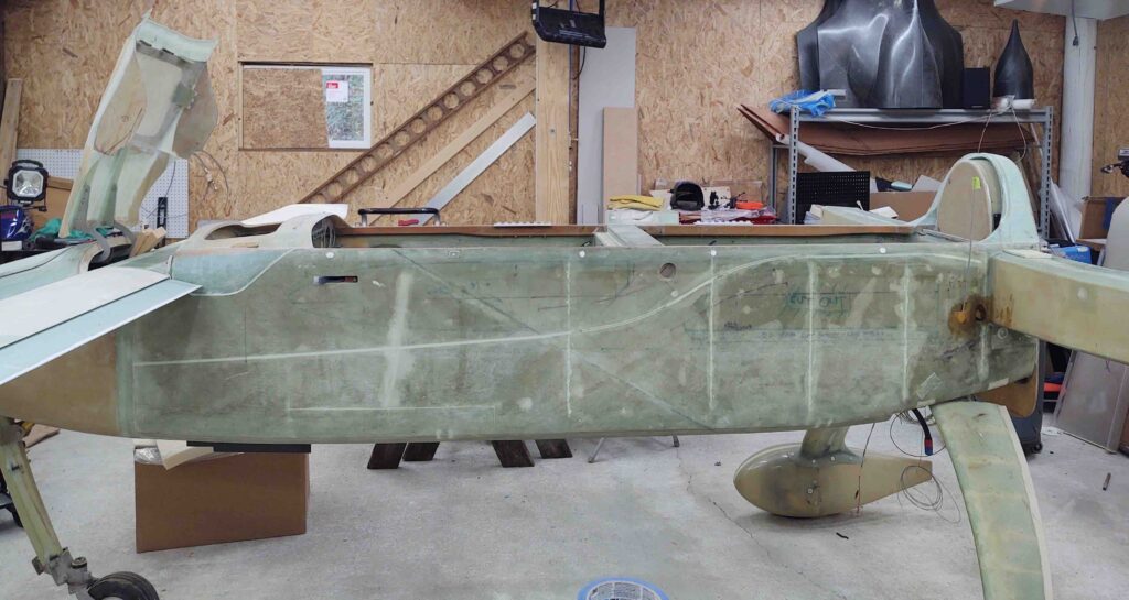
I’ll need the wings to be on before I start measuring and dialing in all the pieces parts for the strake. I don’t really have any help so it will be a one-man job. To make the job of mounting the wings and removing them much easier, I am going to knock out the reversed and secured wing bolt mod that so many canardians do.
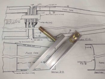
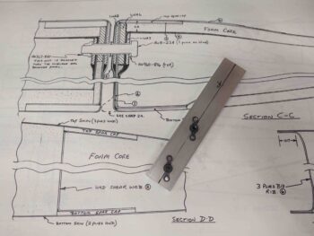
If you haven’t heard of this it is simply having the wing bolts stick out of the CS spar and then having a U-channel bracket that secures them both to the interior CS spar aft wall, and moreover keeps them from spinning. This can be done however the owner/builder wants, with just the outboard bolts or the inboard bolts as well. I’ll be doing all of them in this manner. Then the wing mounting process can be a one-person affair by simply sliding the wing onto the bolts and then ratcheting the respective nuts onto each bolt.
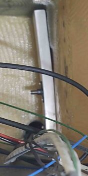
My buddy Marco just did this mod to his flying Long-EZ and had some great tips for me (I’ll cover them as I do this wing bolt mounting mod). One of those of tips, that he researched and discussed with the Old Guard of the canard world, is cutting an access hole in the end of the CS Spar to more easily do the mod. I may not have needed to do this if my setup wasn’t disrupted by yet another mod that I did when building the CS spar: the wire/cable tube I installed that ends on the lower aft corner of the CS Spar’s outboard face.
Why the lower aft corner? If I go back and look at my build log it would probably say, but right now my only guess is that wire/cable tube exit location aligns with the wing wire/ cable channel. Regardless, I can’t merely measure, cut and slide a U-channel in place since I have to work around this wire/cable tube.
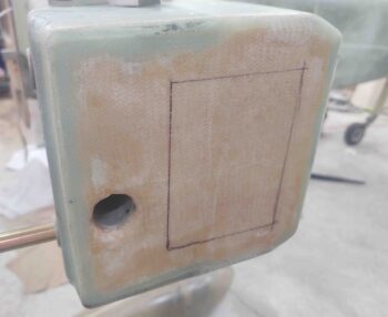
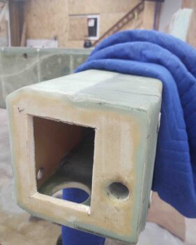
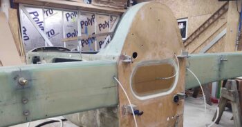
Moreover, whereas Marco used a large hole saw to create a temporary access hole to mount his wing bolts in the spar, I decided to make mine rectangular, with the sides angled somewhat like how you’d cut the top of a pumpkin if making a Jack-O-Lantern. So I marked my temporary access hatch outline.
Then cut it out and vacuumed up the mess.
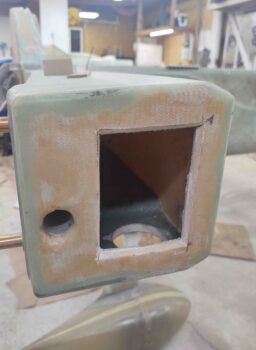
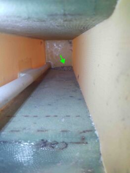
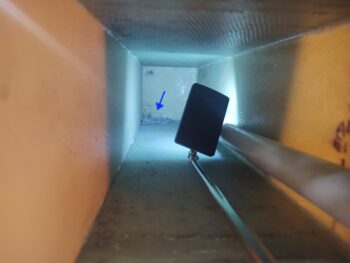
Looking around at my 8-year-old work —akin to opening up yet another time capsule on this bird— I noted a big ‘ol pile of metal shavings in the front inboard corner of the spar. Clearly from when I drilled the wing bolt holes. I of course vacuumed those out as well.
I then cut the same temporary access hole at the left end of the CS spar.
And just like the right side had another pile of metal shavings from when I cut the wing bolt holes. Yep, these got vacuumed out as well.
•••
12 November 2020 — Well, over the last couple of days I’ve been on the hunt for my original wing bolts. I have 6 long ones that somehow I had figured I would use with the reversed & secured bolt mod in the CS spar. But with all my notes and binders still in a bit of disarray from the tornado/hurricane that swamped my hangar, I have some struggles at times to reconstruct my build plans. So I’ll be honest, I have no idea how these long AN8 bolts (and I’m sure rather expensive) fit into the plan?!
I finally found the original four AN8-21A bolts for the outboard bolts, but still could not for the life of me find the interior two AN8-23A bolts for the inboard attach points. Since I need some -8 and -9 CAMLOC/SkyBolt studs for the thru-panel tabs I went ahead and pulled the trigger on another pair of AN8-23A bolts, plus a couple spares. In fact, I ordered some AN8-22A bolts as well just in case I need to add some washers to the wing bolts to shim the wings level.
•••
15 December 2020 — My goal for the evening was to get the inboard wing bolt brackets made up to allow me to install the inboard wing bolts from inside the CS spar facing out and aft, just opposite of how they are installed per plans. Again, with all the wing bolts secured inside the CS spar facing aft it will make it much easier to put the wings on and take them off during the duration of the build.
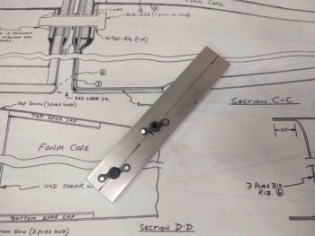
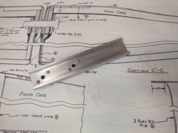
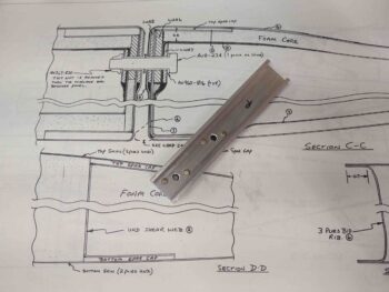
I started by trimming and cleaning up the U-channel brackets.
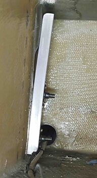
I then set them in place on the bolts (they fit snugly) with the bolts facing in backwards (aka “per original plans”). I then marked a centerline on both the brackets and the CS spar aft wall.
You can see both the centerline and the bracket-securing screw holes on the left inboard bolt hole (I moved the screw hole up slightly on the top).
I then drilled the bracket-securing screw holes and riveted 2x K1000-3 nutplates onto the left bracket.
I then installed the left side AN8-23A inboard wing bolt and the securing bracket inside the CS spar.
I then repeated the same process for the right side. Here we have the bracket centerline marked and aligned with the centerline mark on the aft side of the CS spar. I then secured the bracket with duct tape and drilled the smaller starter holes (bracket starter holes were drilled with it off the CS spar).
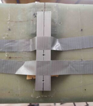
I then drilled out the holes to #10 and installed the K1000-3 nutplates.
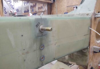
And installed the right inboard wing bolt from inside the CS spar facing out and aft.
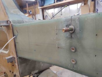
With a 1/8″ thick 2024 plate that’s embedded into the interior wall of the CS spar as part of the inboard wing bolt hard point, it makes it so the bracket is angled slightly when mounted over (and securing) the inboard wing bolt and screwed into place.
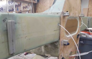
Here’s a shot of both inboard wing bolts mounted inside the CS spar facing aft (again, this is a mod to the original plans).
•••