
Oil & Seat Warmer Heating Systems
[Note: The oil heat system is not per plans and is a one-off modification based on Nick Ugolini’s Heat and Ventilation concepts for Long-EZ aircraft.]
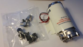
27 September 2016 — While at the RR Saturday evening Central States Association (CSA) meeting hosted by Terry Schubert and Nick Ugolini, I won the auction for one of Buly’s Oil Heat Pumps that I’ve been trying to get my hands on since I learned about them a year or two ago. Luckily, I was able to get this thing WAY cheap and saved well over $100. Just another plus for such an awesome RR!
Last night I took the plunge and spent about 3 hours building my electrical diagram for the Oil Heat System in my bird. I still have some more research to do since specifics on this system are vague at best. After a good discussion with Greg Norman at RR, I’ve reached out to him to get some specifics on his install since he also has this oil pump. Here in the near future I’ll discuss with Buly as well to finalize the architecture. Of course, I’ll be performing a fair number of tests as well to ensure the circuitry is good before this system actually gets installed.
•••
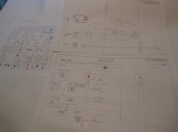
30 September 2016 — Today I did a fair amount of research on the heating system. That rolled into updating a few wiring diagrams to reflect the updated electrical requirements, which included the newly created Heating System diagram (shown below).
•••
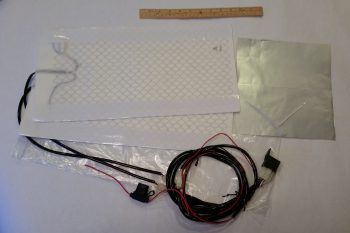
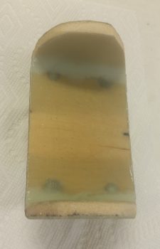
23 January 2017 — I finally found a good, cheap basic heater fan resistor coil for my oil heat system. I got this off of Amazon for about $5. Not bad, and so far it looks like it will definitely work.
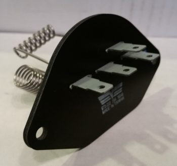
Here’s the backside of the oil heater fan resistor coil. However, since it didn’t come with any specs I had test each of the coil circuits for their resistance values and create a truth table to verify what was what. It took about 10 minutes, but I verified the entire circuitry of the heater fan resistor coil.
[Operational Note: This heater fan resistor coil will not be used in my oil heat system since I have since removed the fan/blower component from the system.]
I also ordered a heated seat pad kit for the front seat and/or possibly both front & aft seats (if I can make it work). The wiring is fairly straightforward and the whole thing will come in under 0.8 lbs. installed. I think I mentioned it before, but I will be wiring both the heated seat warmers and the oil heat system through a DPDT relay so that only one system can be powered on at any given time. This is of course to ensure that the charging system, main power bus, and/or battery isn’t overtaxed beyond the capability of my 40A alternator.
•••
28 February 2017 — Today I had a good discussion with both Buly Aliev and Nick Ugolini regarding the integration of Buly’s oil heater system pump and system design. I have lots to think about still on this system, but one thing I did take away from my discussion with Nick is the heat output is best realized by controlling the speed that the oil pump is pumping in hot oil into the system.
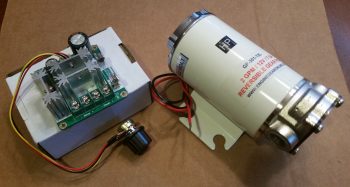
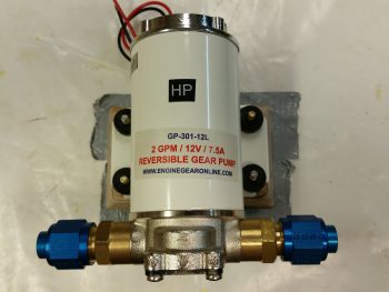
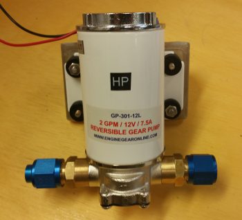
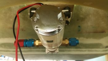
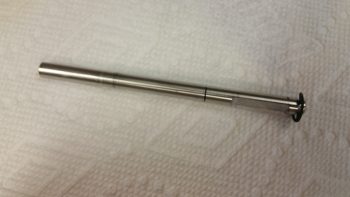
Thus, in able to control the speed of the oil pump, one method utilizes a PWM controller switch, so that’s just what I picked up. I can now say, “Behold, the oil pump and its PWM controller switch!” (not that I will necessarily, but I can if I want . . . !)
•••
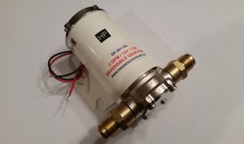
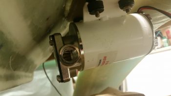
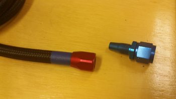
10 March 2017 — Today I received two new brass fittings for the oil pump from Buly. We actually talked a couple of weeks ago and he said he was going to ship them out, but understandably got sidetracked with the sale of his Cozy. Sad to see him sell it… yet another one of the Ol’ Guard out of the game.

Obviously these fittings are somewhat unique, thus the reason Buly sent them to me rather than just have me order some off of ACS. Nick Ugolini did recommend that I acquire fittings for 5/8″ tubing, but Buly had these 1/2″ fittings at the ready, and I figured 1/2″ will do just fine. Maybe these will save a bit on weight with a little less oil coursing through the heating system lines. Below you can see that I test fitted these new fittings on the oil pump. Since these brutes are brass, they of course are significantly heavier than if they were aluminum. But hey, they fit, are in hand and will allow me to have heat in my airplane!
•••
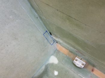
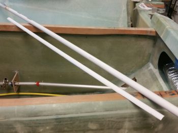
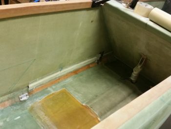
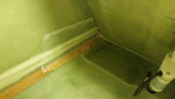
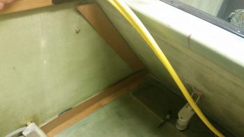
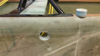
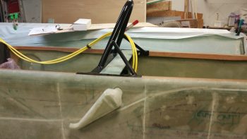
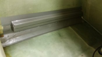
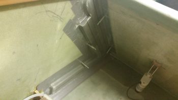
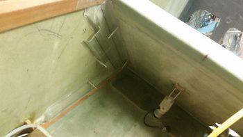
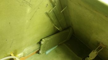
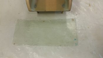
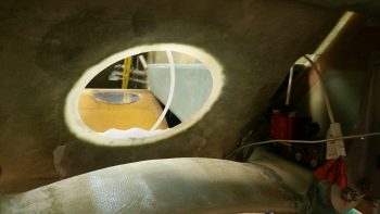
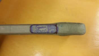
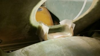
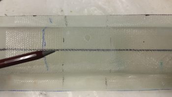
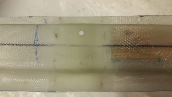
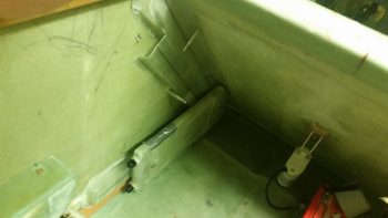
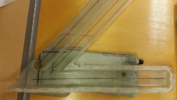
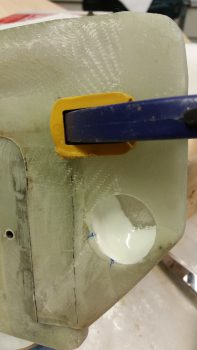
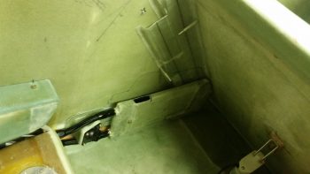
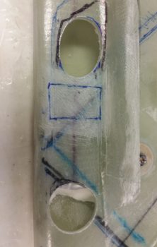
24 May 2017 — Although I hadn’t finished with the right side forward sump wall edge configuration, I wanted to get some glass curing, so I worked on the left side a bit. The pic below shows a small opening in a slight depression in the side wall at the lower left edge of the pilot’s seat back. This opening will carry 3-4 antenna cables to the aft fuselage and eventually the wings. The blue rectangle is where the heating duct will come forward from the oil heat exchange behind the pilot’s seat on the left sidewall. [The oil heat system is another system that I pretty much just finalized the configuration for.] So before the fuel sump front wall goes up, there needs to be some accounting of the items that will traverse across the left sidewall edge of the front fuel sump wall.
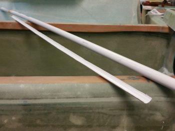
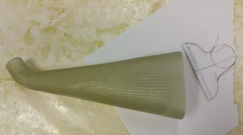
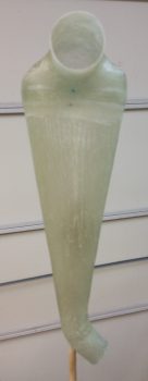
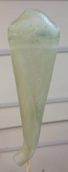
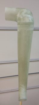
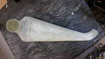
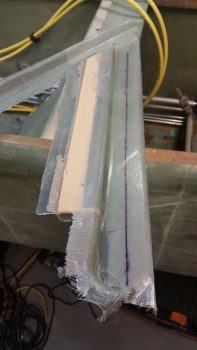
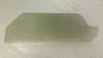
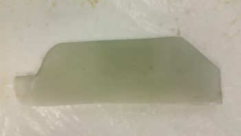
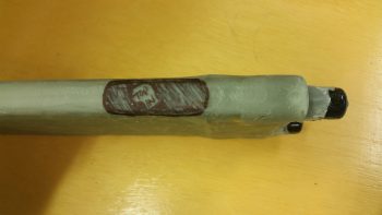
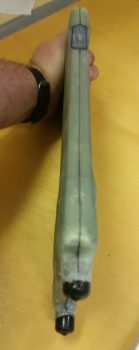
Additionally, the heating duct that I will be putting in actually needs to be run right over the channel that the antenna cables were meant to go. Thus, to protect the antenna cables, make them removable, and still keep them in the same place, I cut out about a third of a side of one of my German “PVC” pipes. These things are really thin, but fairly strong. I weighed the piece that I used and it came out 0.92 oz. Not bad.
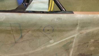
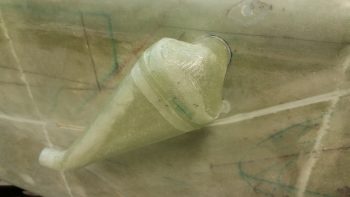
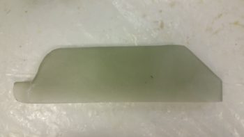
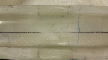
Here’s a shot of the other side of the piece of pipe that I’ll be using. I cut it length ways using a utility knife (that’s how thin it is), so it’s not a perfect cut.
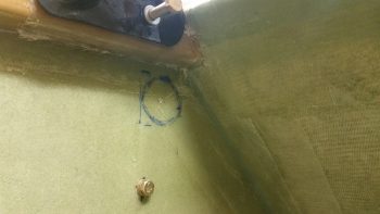
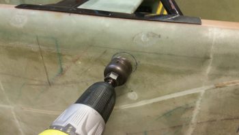
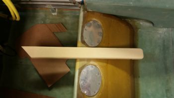
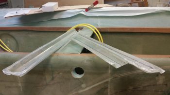
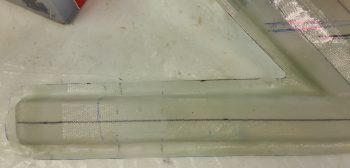
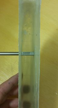
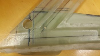
After a fair amount of sanding to expand the opening a bit on the lower left side pilot’s seat, I was then able to slide just a peek of the antenna cable channel cover into the opening. I wanted just enough poking out to feed the antenna cables through.
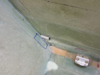
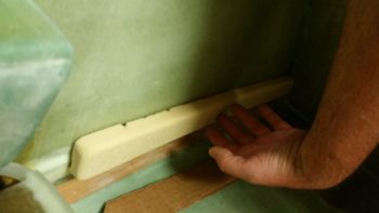
I taped the antenna cable channel cover to the side wall groove in the GIB area, and then 5 min glued it in place.
Using dry micro, I then covered the depression that ran the length of each side of the antenna cable channel cover (above & below it), which is caused by essentially having a segment of smaller circle sitting inside the segment of a bigger circle.
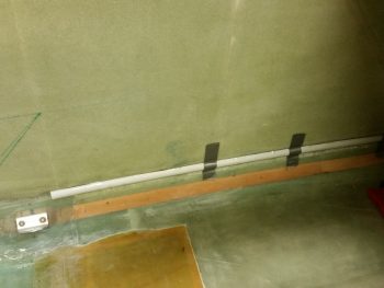
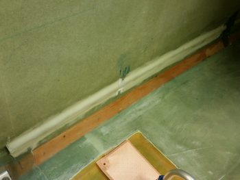
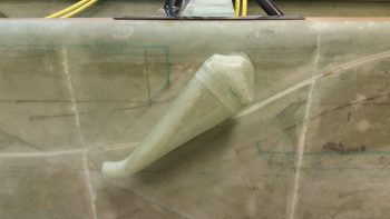
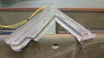
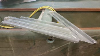
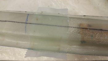
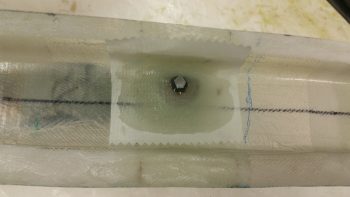
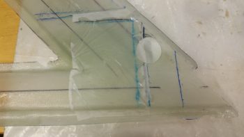
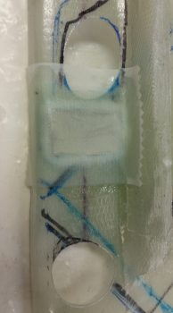
I then laid up 1 ply of BID in two separate pieces onto the antenna cable channel cover. Installing & glassing this antenna cable channel will allow me to account for it when I mount the fuel sump front wall.
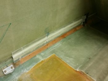
Here’s a closer shot of the glassed antenna cable channel. I still have maybe a foot left to glass on the forward side, but I wanted to get the lion’s share of this laid up tonight. With the really dry micro and the lightweight conduit piece, I’d be surprised if this whole antenna cable channel weighs more than a couple of ounces.
•••
25 May 2017 — I started off today doing a bunch of research on the Silver Hawk EX fuel injection system to figure out the mechanical lever configurations and how the throttle handle and mixture lever would control the fuel injection servo since I needed this info to get a good approximation of where the throttle and mixture cables would be run down the fuselage sidewall. This allowed me to better figure out where my oil lines will go inside the cabin for the oil heat system.
I also took a good look and assessed the placement and installation of the oil pump for the heating system.
•••
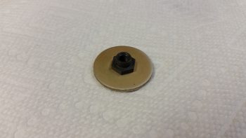
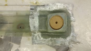
26 May 2017 — Today I pulled my table saw out of the shed and cut a 1/4″ thick piece of Finnish Birch plywood for the oil heat pump mounting pad. I also beveled the edges in prep for it getting glassed into place.
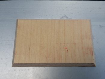
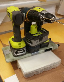
I then tried out the fit of the oil heat pump on its new mounting pad. The 4 each AN3 bolts will stick through the pad –with the heads embedded in the plywood on the back side– to secure the oil heat pump. In addition, before I glass all this I’ll sand the beveled edges of the pad to remove any sharp corners.
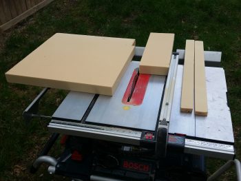
While I had my table saw out I took the opportunity to cut up some 2″ thick urethane foam for some plugs. The 2 longer strips on the right will be plugs for the heat & air ducts, while the block in the center is the GIB right armrest storage pocket plug.
•••
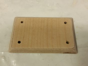
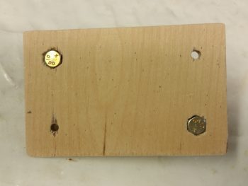
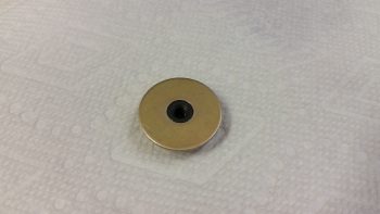
29 May 2017 — Today I decided to knock out making the oil heater pump base. I started with the 1/4″ Finnish birch plywood plate I cut out the other day. I rounded over the edges and then drilled 4 x 3/16″ holes.
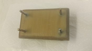
I then marked the heads of the only 2 AN3-12A bolts I have onto the back of the mounting bracket and dug the wood out to keep the bolts from spinning.
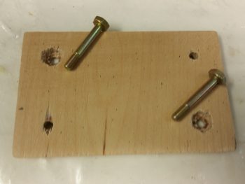
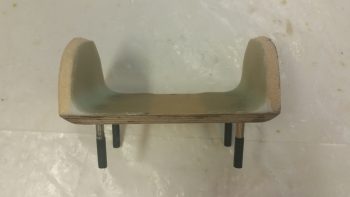
The bolt heads are flush with the bottom, can’t spin, with still a good amount of wood to keep them in place. Still, this plate will get about 5 plies of glass to hold it in place.
Here’s a side view showing the bolts in place.
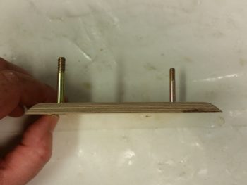
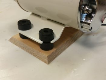
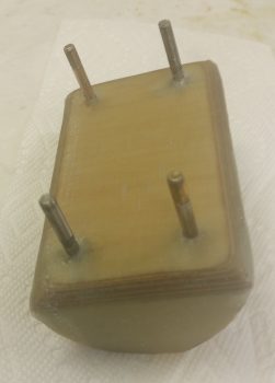
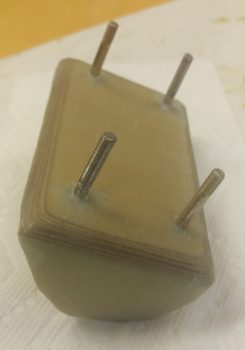
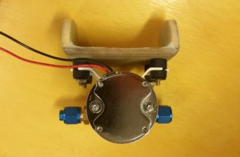
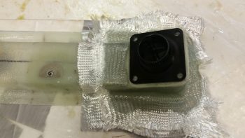
Since I didn’t have any more AN bolts, and I wanted to get this mount finished, I stole the two 1-1/4″ bolts from the fuel pump and mounted them in the oil pump mounting base. I then taped up the bottom of the vibration mounting pads, floxed the bolts in place and then set the oil pump in place over the floxed bolts.
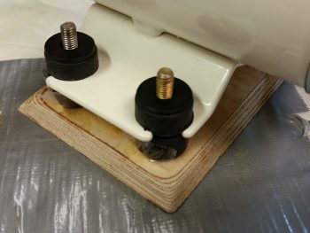
And here’s a couple more shots of the oil pump on its mounting base.
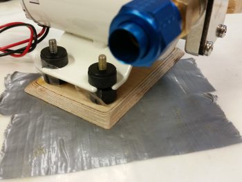
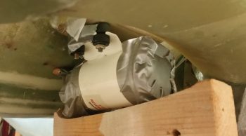
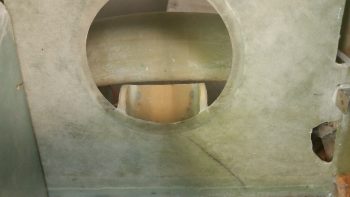
I then used the oil pump attached to its mounting base to figure out where in the world I was going to mount this thing in the Hell Hole. Since I just recently discovered that it is best to mount it horizontally (interesting, but that’s what it says!) I found a spot centerline of the aircraft, immediately forward of the gear bow and just aft of the GIB seat.
This all ties into the sump in that before I glass the front side of the fuel sump front wall, I need to know if I’m going to mount the oil heat line fittings into the LEFT sump front wall extension.
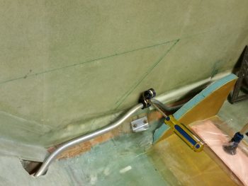
To figure out my oil heat oil lines, I needed to make some. So I did. I made the feed line that feeds the oil to the heat exchanger from the oil pump. It all looked good on the top side . . .
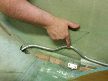
. . . as you can see here . . .
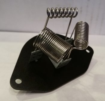
But since I don’t have a 1/2″ tube bender, I resorted to a spring kit for bending the 1/2″ tubes. The spring works well enough on simple bends, but it just can’t handle really tight turns without crimping or flattening the tubing — as you can see in this real tight turn to the right.
I’ll assess further, but right now I’m thinking at least the oil feed line will most likely need to be a braided cable to provide me the flexibility that I need.
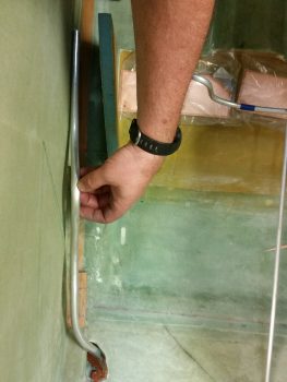
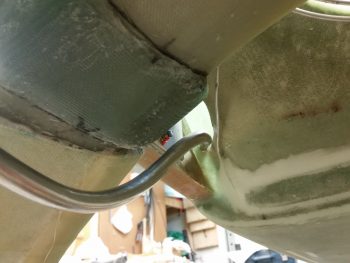
With that, I then made up an oil return line. Since it doesn’t need to make a hard right turn to get to the oil pump, I didn’t think this one would have as much of an issue as the oil feed line. And it appeared not to.
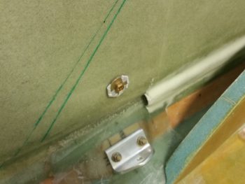
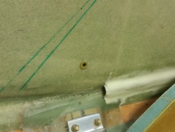
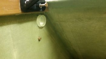
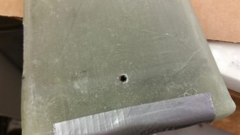
One interesting point in the pic below: I played around with the spacing and tubing run for a bit before deciding on exactly where I wanted the Adel clamp to be located to hold the 2 oil lines (feed & return). Well, I reached into my pocket to get my trusty Sharpie, but, uh, no Sharpie. So, I picked up a small Phillips screwdriver and gave it a nice sharp rap to make a mark…. well, it was a bit harder than I thought and it made a nice dent in the wall. So, another wiggle and another rap, and in she went…. I guess this will be a RivNut hardpoint vs a Clickbond!
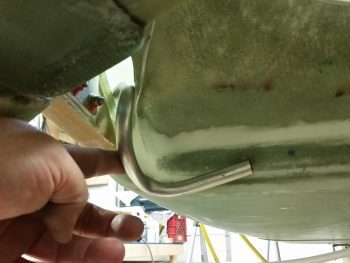
A shot of the oil return line from below.
For now I’ll just count the oil return line good, and then later when I finalize the firewall configuration I’ll cut the oil return line and terminate it with a fitting.
[Operational Note: Currently, the only hard aluminum tubing used for the oil heat system will be the oil feed line from the engine, which starts on the cold side of the firewall at the bulkhead fitting and terminates at the OIL IN side of the oil heat pump.]
•••
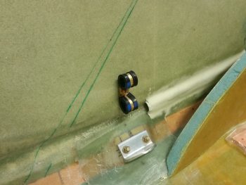
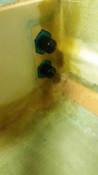
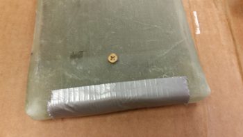
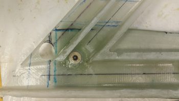
30 May 2017 — During today’s adventures I floxed a RivNut hardpoint in place over the left GIB seatbelt bracket for the oil heat lines.
Here it is after cure…. looking a bit lonely, eh?
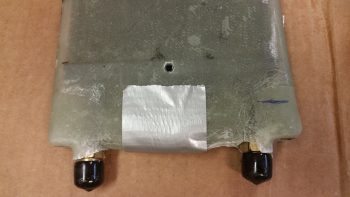
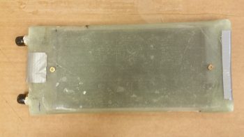
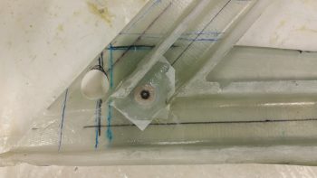
So I gave it some friends. . . 2 Adel clamps for the oil feed and oil return lines to/from the oil heat exchanger that will reside on the left sidewall, immediately aft of the pilot’s seat, about midpoint up the wall.
•••
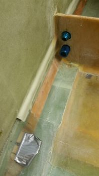
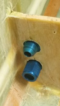
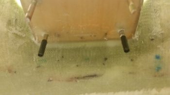
1 June 2017 — Today I started out by cleaning up the 2 oil line reducer fitting mounting holes in what makes for a mini-bulkhead on the left side of the fuel sump front wall for the pair. I then test fitted the oil heat line reducer fittings in the holes.
•••
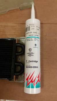
5 June 2017 — Today, to prepare the left side sump accoutrements before proceeding with mounting the left armrest, I needed to mount the oil heat line reducer fittings in the fuel sump front wall left side extension. Since I may need to tweak or modify the oil heat configuration at some point in the future, I wanted these reducer fittings “hard” mounted, but not permanently, if you will. Thus, I used Silicone RTV to keep them in place, and slathered them up and set them in place in their respective mounting holes.
I then left the RTV alone to set up & cure.
•••
13 June 2017 — This morning I spent a couple of hours planning and diagramming out my oil heat system. I’ve been collaborating with Dave B. on it, but still need to query Nick Ugolini on some of the specifics of the oil heat system he developed.
•••
15 June 2017 — Today started off with a long discussion via phone with Nick Ugolini about the oil heat system. I had a bunch of burning questions and Nick was of course gracious enough to answer all my questions.
After spending over a good hour on the phone, I then documented all that Nick and I had discussed.
After my discussion with Nick, I also tweaked my air intake scoop expansion chamber and played around with some potential configurations and locations on the fuselage.
•••
21 June 2017 — Today I 5-min glued the remaining center area –top & bottom– of the piece of German “PVC” pipe that I’m using as my antenna channel cover.
After the 5-min glue cured, I then got to work mixing up some thick micro, slathered it on each side of the channel cover, and then laid up 1 ply of BID over top of that. Of course I peel plied it after I was done with the layup.
I then decided to take on one of the more challenging tasks on my list: the ram air inlet and expansion chamber for the oil heat system and fresh air intake. This ram air inlet will also serve to pressurize the cabin more to help offset the negative characteristic of Long-EZs to suck all the bad stuff (cold, rain, small reptiles, etc.) from the outside . . . as per Nick Ugolini who has compelling evidence that his findings work!
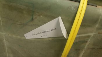
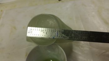
I made a bad assumption in thinking that the urethane foam I have on hand was 2.5″ thick, when in fact it is only 2″ thick. I had already confirmed with Nick that instead of a 3″ round diameter expansion chamber, that I would be making mine more oblong, or oval, shaped to save some room in the RHS baggage area. I had planned on making it 3.6″ high x 2.4″ wide. Well, I ended making the expansion chamber just a hair longer since that was the only dimension I could control with this foam, to still come up with approximately the same volume as I would have before.
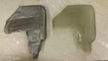
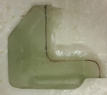
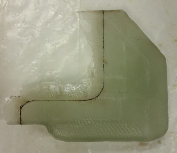
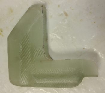
I then shaped the curved inlet and expansion chamber out of the urethane foam.
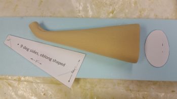
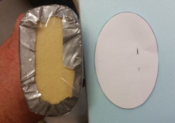
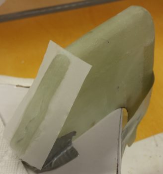
After finalizing its shape, I then covered it with duct tape first, then with clear packing tape.
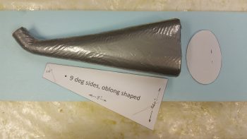
Here’s a general look at how it stacks up with my planned shape.
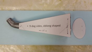
As you can see, the cross section turned out to be a bit more square than I had originally planned (Hmmm, I wonder if Burt ever had this thought cross his mind about the fuselage he designed . . . ha!). Again, to make up for some of the 0.4″ in width that I lost due to the urethane foam block width.
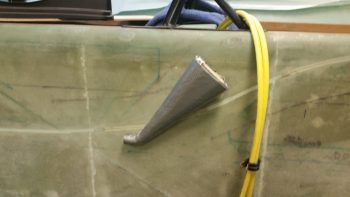
I then very quickly mocked it up on the sidewall to see how it looked.
I then also quickly made up a glassing spit for the ram air inlet & expansion chamber.
Here’s a better shot of the glassing spit. If you’re thinking that I got really fancy with my upright (I know you’re not!), it might look familiar: it’s one of the sump test ribs that I cut out of OSB plywood.
I have to admit I failed in my layup goal here. Except for a reinforcement ply of BID at the front and the back for interface strength with other upcoming duct pieces, I was going to use spare UNI for the entire layup since I have a ton of it laying around.
Ugh!
I couldn’t do it…. what a royal pain that stuff is trying to go around any smallish curves. I did got a couple of plies on, but the small front 1″ opening was going all wonky on me and after fighting off the attack of the killer strings for over half an hour, I finally threw up my hands and magically one of them landed on a piece of BID . . . A SIGN! ha!
Ah, laying up a ply of BID after fighting UNI is like eating real butter! Smooth & silky! Anyway, I added a final ply of BID, peel plied the ends and the seam down the side and called it a night.
Mission complete. Tomorrow I won’t get much done. Out of town visitor flying through to fly out, then a birthday party after that . . . busy, busy! I will continue to work on both the sump and the GIB area stuff for a few days before heading north, or forward, to the pilot’s seat area.
[Operational Note: With the less than stellar performance during testing of this inlet, I have changed my inlet design to remove any bends or angles for air inlet & exit. I’m also moving the actual inlet location from below the strake to the LE of the strake.]
•••
24 June 2017 — Today I went down to the shop and started designing the ram air inlet expansion chamber top and transition for getting the air through the fuselage sidewall and into the heating and fresh air ductwork. The lines you see at the bottom of my drawn top piece are successive height-shortening lines to get the top as low-profile as possible so this thing will fit correctly inside the left baggage compartment mounted to the existing fuselage wall (when the airplane is finished it will be on the inboard baggage compartment wall).
I then cut out a test piece out of urethane and quickly covered it with duct tape, mainly to strengthen it since it was bit fragile in spots. I set it aside for a while to let the design germinate a bit in my brain while I moved on with other stuff.
[Operational Note: With the less than stellar performance during testing of this inlet, I have changed my inlet design to remove any bends or angles for air inlet & exit. I’m also moving the actual inlet location from below the strake to the LE of the strake.]
•••
25 June 2017 — On the oil heat system, I have a couple things to note before I start on the discussion of my latest build tasks. First off, since the oil heat mod is of course not discussed in the Long-EZ plans, there’s not exactly an obvious place to put it categorically. I may break it out later in say a Chapter 27 – Environmental Controls or something, but for now, since the oil pump (and the now superseded fan) is electrical, I have it on a subpage in Chapter 22 – Electrical. Clearly much –if not the majority– of the oil heat system is not electrical, but that is where it resides topic-wise for now.
Secondly, just a point to say I’m still having camera issues since I thought I had a few more good pics of this process, but they turned out to be crap. So, we’ll move on with those decent pics I do have…
I cleaned out the foam form innards from the ram air intake expansion chamber top and 90° transition 1-1/2″ diameter port. The port will traverse through the sidewall into the main cabin just below the left longeron & just aft of the pilot’s seat back. For the 1.5″ diameter port, I looked all around for something that would make a good form, and eventually ended up using an Ibuprofen bottle since it was exactly 1.5″ in diameter. After taping it in place I could tell it was going to work perfectly!
After removing the foam, I spent a good 30 min. sanding the inside of the top transition chamber to smooth it out.
Again, here’s a shot of the 1.5″ ID opening. After leaving the expansion tube, all the ductwork will be constructed with the same cross-section capacity as 1.5″ SCAT hose.
I then prepped two 1″ wide x 10″ long 1-ply BID prepreg setups to glass the top transition piece onto the inlet/transition chamber body. I mixed up some MGS epoxy with fast hardener and then applied a thin film of fresh epoxy around the ends of each piece that would get glass.
I then wet out the prepregged BID and laid up the first ply with the seam on the outside of the two joined pieces (opposite the 1.5″ opening). I then laid up the second ply opposite of that with the seam right under the 1.5″ round opening.
I then cut a 1″ peel ply tape down the middle and peel plied just the edges of the newly laid up BID. After about 30 min of curing, I then set the glassed assembly in the top of an open jug and put it in front of a heat lamp for about 30 min each side. I had to take the shot below since I couldn’t help but notice how much it looked like a Cobra ready to strike (which I have been face-to-face with, but alas, that is another story!). With fast hardener that did it for a workable cure cycle.

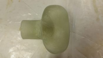
I then pulled the peel ply and cleaned up the edges of the glass. Here’s the new single-piece ram air inlet, expansion chamber and transition port ready for install.
[Operational Note: With the less than stellar performance during testing of this inlet, I have changed my inlet design to remove any bends or angles for air inlet & exit. I’m also moving the actual inlet location from below the strake to the LE of the strake.]
•••
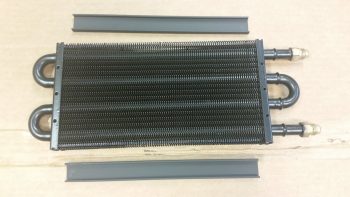
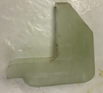
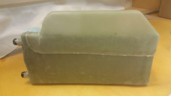
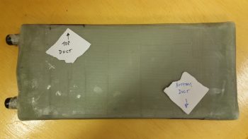
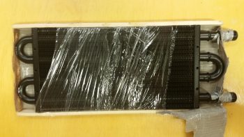
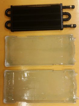
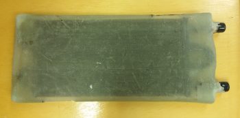
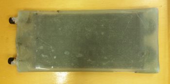
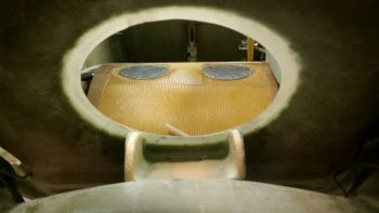
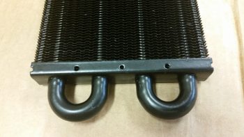
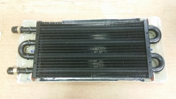
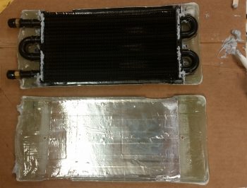
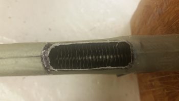
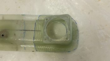
27 June 2017 — Today I set my sights on the oil heating system. After inspecting the heat exchanger, I realized I could simply pop off the plastic protective runners on each side. It didn’t take long looking at the heat exchanger to realize that my airflow in, through and out the heat exchanger was going to take place via the long sides of the unit.
I then cut some 2″ wide cardboard strips out to represent the width, albeit not the depth (which is 0.75″) of the heating & fresh air ducts. I played around with this whole setup for a good 45 minutes before determining what my next steps will be. Since there’s no exact plans for building the ductwork for the heating and fresh air system, this will be a bit more slow in the creation and build of this whole thing. Plus, I got some good data points today and will continue to press on with building the oil heat system over the next 2-3 weeks.
•••
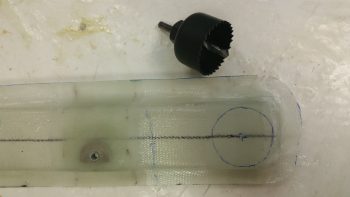
28 June 2017 — Today I set my sights on getting the ram air inlet, expansion chamber and transition piece installed on the (current) exterior side of the fuselage. I double checked my dimensions, moved my initial drill point forward and down just a hair, and then drilled it with a small pilot bit.
And Bingo! Center of mass on the interior marked hole.
I double checked the overall configuration of how the ram air inlet, expansion chamber and transition piece would mount on the exterior sidewall (which will be inside the strake baggage compartment when the plane is finished). I then loaded up a 1-1/2″ hole saw bit into my drill and literally pulled the trigger!
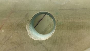
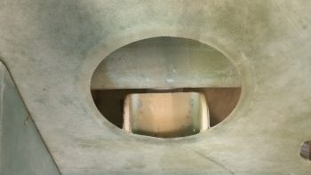
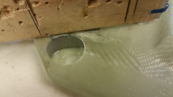
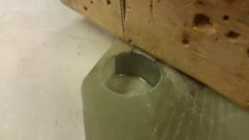
Here’s the initial 1-1/2″ diameter hole into the fuselage sidewall, obviously just aft of the pilot seat and just under the left longeron. You can see the drilled out plug sitting atop the longeron.
Here’s a couple of shots of my test fitting the ram air inlet, expansion chamber and transition piece into place. The transition tube on this component is 1.5″ ID, which means I had to widen the hole out a bit for this piece to fit into place. Also, I had to radius the outer perimeter of the hole a bit from around the 5 to 10 O’ Clock position for this thing to mount close enough to the sidewall.
I intentionally glassed the 1.5″ ID air transition tube of the ram air inlet, expansion chamber and transition piece a little long so that it would definitely clear the inside surface of the fuselage sidewall. However, the excess, overhanging tube edge will be cut down so that the transition tube edge is flush with the interior surface of the sidewall, since the air will immediately flow into the heating and fresh air ductwork at this point.
You know me, the peel ply king, and the one time I thought I could get away with not doing it, I ended up needing to sand this sucker down… well, in the end not all of it, but a good portion of it! I call this picture: The Mummy in Repose …. haha!
Now, I need to research just how far away from the outer skin the intake needs to be mounted, so the ram air inlet, expansion chamber and transition piece floxing-in & glassing is on hold until I finalize these installation specs. If anyone out there is smart on this, by all means send me a note! Here it is one last time, mocked up after I sanded it down.
[Operational Note: With the less than stellar performance during testing of this inlet, I have changed my inlet design to remove any bends or angles for air inlet & exit. I’m also moving the actual inlet location from below the strake to the LE of the strake.]
•••
29 June 2017 — I then sat down and went over some info my buddy Dave Berenholtz had sent me on oil heating, reread Nick Ugolini’s write-up in the latest CSA newsletter, and then proceeded to finalize my oil heat and fresh air intake ductwork plan.
I then went out to my shed, pulled out the table saw and ripped some urethane foam in 3/4″ wide pieces. With the thickness of the foam being 2″ (I didn’t forget this time!), that makes for the perfect form –according to Nick U.– for making homemade fiberglass heat & air ducting. According to Nick this glass ducting weighs about 25% of the equivalent length of 1.5″ round SCAT duct tubing.
I then cut each foam piece to length and radiused the outer corners.
For the piece running horizontally over the antenna cable channel conduit I had to create a trough along the entire length of the back side of the foam form.
I then taped the urethane foam form in place and marked the centerline. Marking the centerline is a fairly important thing not to forget since it allows perfect alignment with the CL of the prepregged glass as it’s laid up.
I then cut the main air feed foam form to shape and length to run from the air inlet that I just drilled last night down to the lower corner to intersect the horizontal duct form that I just taped into place. I then taped the main air feed duct foam form in place as well.
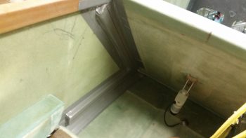
I didn’t get a pic of the last duct piece before I glassed it all, because it actually got mounted after the main air feed duct UNI glass was laid up to provide a dividing wall between the two ducts via the aft wall of the main air feed.
I then glassed the parallel duct aft of the main feed and overlapped the glass onto the main feed top to created two channels with a dividing wall. The glass at the bottom edge of both of these leaning vertical upright feeds overlapped onto the bottom horizontal duct, so that when I glassed the bottom duct form it simply created one big layup with the 3 ducts all tied together. In fact, these ducts will be very close to final configuration without much cutting or major work needed for the airflow to get to where it needs to . . . pretty cool, eh?!
Another cool thing about the layups for these ducts is that I did them ALL with leftover “trash” glass by using overlapping plies of UNI to create a 2-ply prepregged setup with each ply of UNI biased at around 30°-45° in opposite directions.
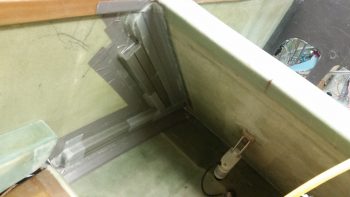
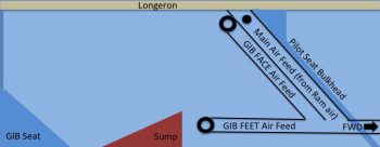
I’m calling this Phase 1 of the ductwork glassing & installation. Here’s a diagram showing the ducts I glassed tonight:
And here are the remaining phases (a loose guideline of how this install will flow . . . I won’t necessarily be strictly adhering to it):
- Phase II – Heat exchanger glassing
- Phase III – Ductwork interface holes drilled and valves built
- Phase IV – Ductwork installed with heat exchanger and valves in place
- Phase V – Oil pump installed & oil lines run
- Phase VI – Pilot seat area ductwork constructed and installed
- Phase VII – Instrument panel forward ductwork constructed and installed
- Phase VIII – Valve cables terminated and handles installed
Obviously I didn’t get to the left GIB armrest forward bracket, although I did spend a good 20 min today locating my 39/64″ drill bit to create the PTT button installation hole! Tomorrow I plan on glassing the left GIB armrest forward bracket and should have it finished no later than Monday. In addition, I plan on glassing the oil heat exchanger as well in prep for mounting it over (eg inboard) of the Phase I ductwork I did tonight.
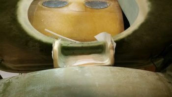
Here’s a general idea of how the heat exchanger box will tie into the ductwork that I glassed tonight:
It may a bit difficult to follow in diagram form, but after it’s glassed and installed it should become much clearer on how it all operates.
•••
30 June 2017 — Today I started back working on the GIB area heat & fresh air ducts that I laid up last night. My first task was to drill some 3/32″ holes into the flanges and install clecos to ensure I would later have the correct duct alignment when remounting the ducts back in place.
I then removed the clecos and fought for a good 30 minutes to get this ductwork assembly off of the interior fuselage sidewall . . . .
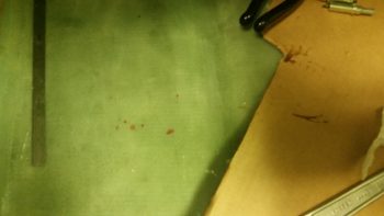
. . . notwithstanding major puncture wounds to my finger and thumb and a fair amount of blood!!! Literally blood, sweat and tears in building this plane!
I removed the foam & tape for both the main air feed and the horizontal GIB lower air feed, but the air feed that goes back up top for the GIB high air feed I couldn’t remove without a lot of difficulty unless I trimmed the glass flange that will secure the shared duct wall with the main air feed. This flange is from the main air feed and had I not subsequently glassed the adjoining parallel GIB high air feed duct right next to it, it would have stood on its own as a “normal” duct without being integrated into a 2 channel duct (or 2 separate ducts sharing an internal wall).
Well, I trimmed down all the flanges and was able to remove the foam from the GIB high air feed duct. I didn’t weigh this ductwork assembly but it is super light, as one could imagine with it being just a couple plies of UNI.
I then clecloed the air ductwork assembly back in place after cleaning up a few spots on the internal fuselage sidewall.
I snapped this shot of the main air feed as seen from the external fuselage side, through the ram air inlet, expansion chamber and transition tube hole.
•••
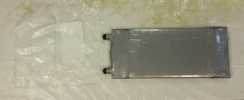
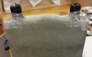
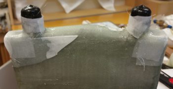
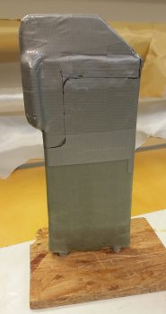
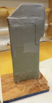
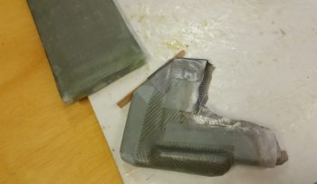
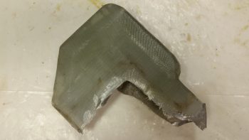
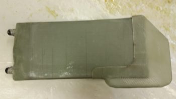
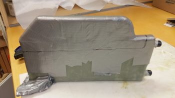
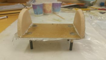
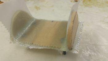
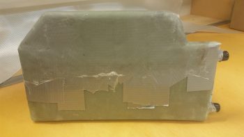
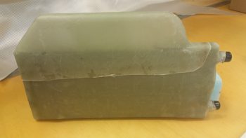
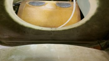
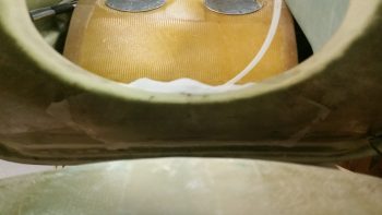
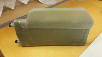
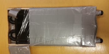
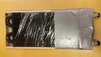
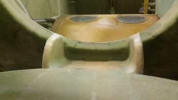
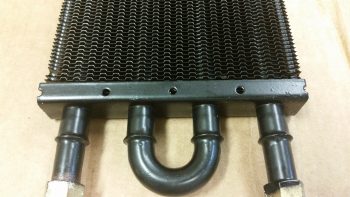
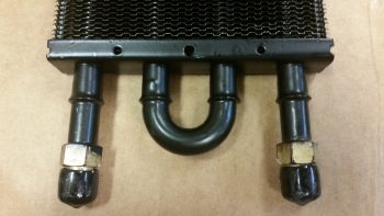
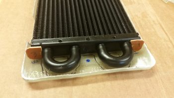
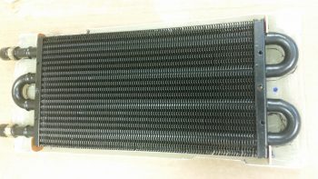
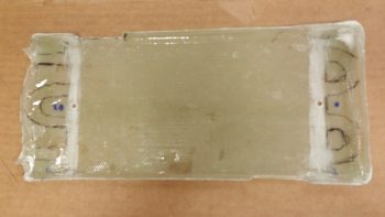
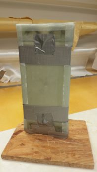
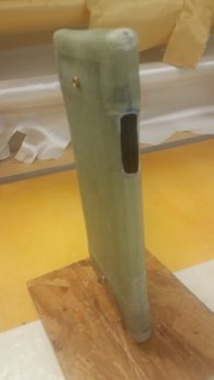
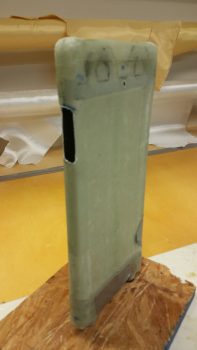
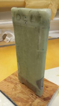
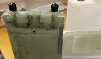
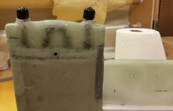
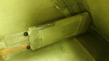
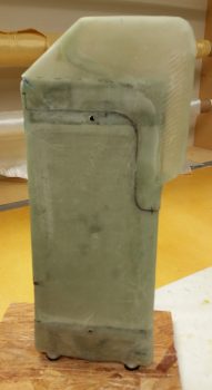
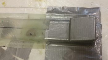
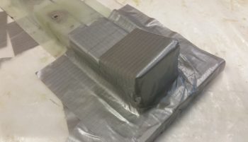
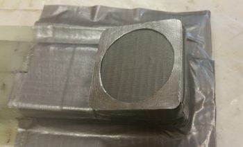
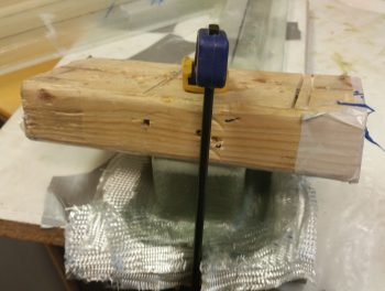
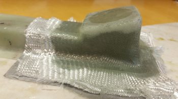
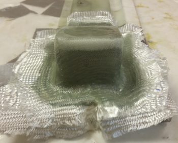
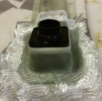
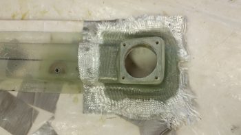
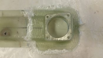
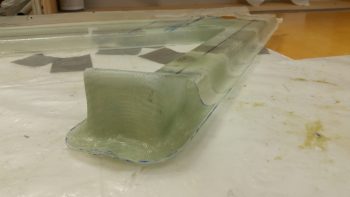
3 July 2017 — Today I focused on glassing the heat exchanger. With help from my lovely assistant (Stacey was visiting from North Carolina and helped with both the prep and the glassing of the heat exchanger… and I have to say, it was great having an extra pair of hands on this somewhat challenging layup!) I taped on two 1/4″ thick rounded wooden runners on top and bottom (that I cut on the table saw Saturday), made some flat cardboard end caps for the U-shaped tubing on each end to make the whole cover a more even rectangular shape, and then wrapped it all in plastic. I then taped it all up, first with duct tape, then with clear packing tape.
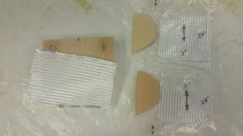
We then cut out BID to make up a 2-ply prepreg setup for each end.
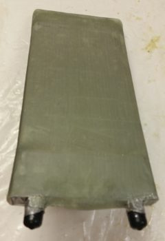
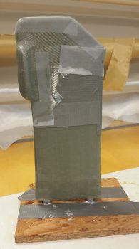
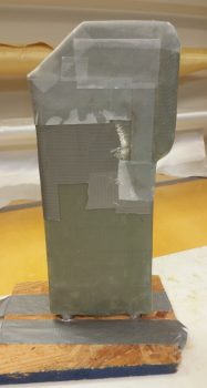
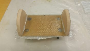
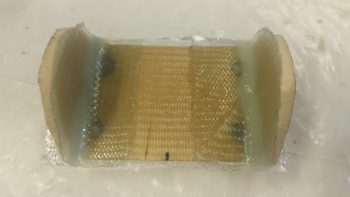
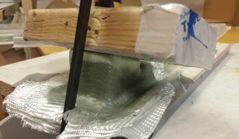
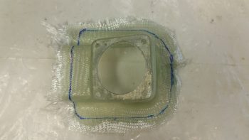
We then wet out the prepregged BID and laid up the end pieces. Then over the end pieces, we wrapped and wet out 3 individual plies of BID, one at a time around the entire middle area of the heat exchanger. The corners did give us a hassle, so on the non-AN fitting end I used a bit of micro in each corner and laid up some “corner cap” pieces of BID. I left the corners on the AN fitting side alone for now and will glass them during round 2 of enveloping the heat exchanger in glass. After laying up all the glass, we peel plied it all and let it cure as we went out to meet some other friends for dinner.
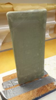
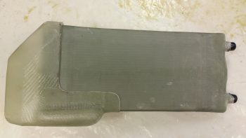
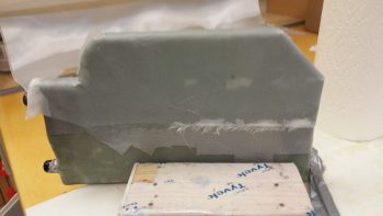
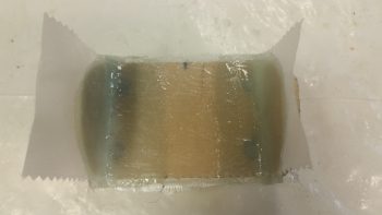
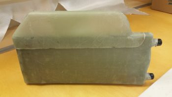
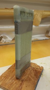
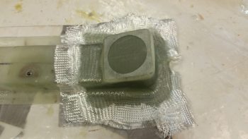
Above and below are actually shots of the glassed heat exchanger after I pulled the peel ply.
•••
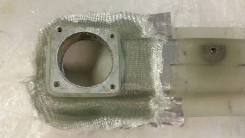
5 July 2017 — Today I started off by prepping the corners of my recent heat exchanger BID cover for glass. I had actually glassed on a couple plies of BID during the initial glassing of the heat exchanger cover, but with so much finagling of the glass to get it to lay down right, the corner plies were mangled beyond use so I just pulled off the blobs of BID and chucked ’em.
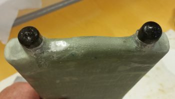
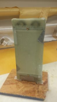
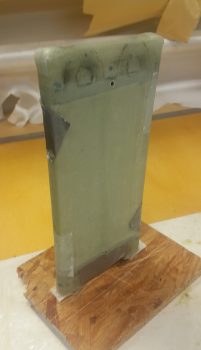
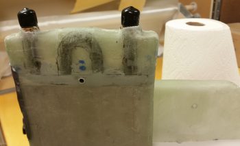
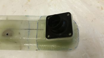
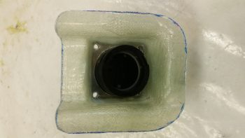
Now it’s time to remedy the exposed corners immediately adjacent to the AN fittings (black caps) on the oil inlet and outlet tubes of the heat exchanger. I knifed some dead glass away and sanded the corner areas in prep for the 2-ply BID layups.
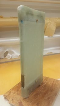
I then laid up 2 plies of BID on each corner and peel plied the layups.
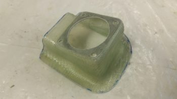
Later, the layups on the two corners of the heat exchanger had cured. I pulled the peel ply and cleaned up the layups while they were still in that nice “green” stage.
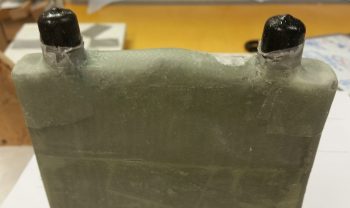
Here’s another shot of the layups on the two corners near the AN fittings of the heat exchanger.
•••
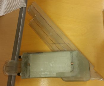
7 July 2017 — Today I set my sites on knocking out the lower cross connect duct that comes out of the oil heat exchanger and transits the hot air into the ductwork. I played around for quite a while to figure out the exact duct size, especially since it was a variable along with the height of the heat exchanger off the cockpit floor.
Ok, my “standard” ducts are 3/4″ wide x 2″ high, which provides a close approximation air volume wise as 1.5″ round SCAT tubing. The optimal height of my heat exchanger off the floor is 0.9″ (vs. 2″ high), so I clearly had some hard configuring to do.
Since the heat exchanger sits over (actually “adjacent to”) the existing ductwork that I just created –with the majority of it being over (again, “over” as in covering) the horizontal air feed to the GIB– I decided to use the area UNDER the horizontal air feed that is just outboard & to the left of the heat exchanger for a wider/flatter duct, thus letting me reclaim the approximate amount of volume lost by having to shorten my duct to 0.9″ (vs. 2″ high).
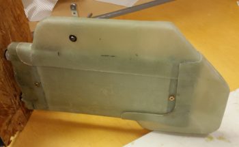
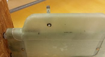
Thus, in the first pic below, you’ll see what looks like the goiter-type protrusion that sticks out on the bottom of large ocean-going vessels. This is the widened horizontal segment of the lower heat exchanger duct, which then makes a 90° turn upwards along the forward edge of the heat exchanger until it empties out into the ductwork (near the angled part).
Additionally, the angled corner you see in the pics below is actually the intersection of the heat exchanger outlet duct where it meets the pilot seat back (NOTE: In the pics below, the heat exchanger is mounted into the board with the aft edge down).
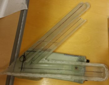
I then laid up a bunch of UNI scraps as the first ply of glass and then laid up a ply of BID over that. I peel plied a bunch of the edges and then took off to have dinner with a buddy of mine.
Upon my return from dinner, with the glass at a perfect “green state,” I cut the short edge and the slanted corner glass right down the middle. I then slowly worked the rather pliable glass off the heat exchanger and then did my best to ensure all the glass was sitting exactly how it was while it was on the heat exchanger… so it would be correctly shaped when cured.
Obviously, my other option was to let it cure on the heat exchanger, Fein saw it off in 2 halves, then glass the halves back together. Not only did I want to avoid the weight, glass usage, and hassle & time of another layup, I didn’t want to accidentally cut into the heat exchanger cover that was just a scant couple of duct tape plies from the glass I was cutting.
•••
8 July 2017 — Today I started by pulling the peel ply off the heat exchanger bottom duct and cleaning it up.
Here’s the inside foam that I never got a pic of before I taped it up. Just after I took this pic I dug it out of there.
Here’s a couple shots of the tape (with the foam removed!) that I used as the form and the actual bottom duct piece.
I then marked up the heat exchanger bottom duct for trimming with the Fein saw.
I then trimmed the bottom (outlet) heat duct with the Fein saw.
And then placed it back onto the heat exchanger cover to test the fit. So far all looks great!
I then placed it inside the cockpit where it will sit once installed in the plane. Again, the fit and finish are just right and all is a go at this time.
I then spent a good hour+ shaping a piece of urethane foam as the form for the heat exchanger top duct, and then taping it into place. Again, the angle you see at the corner of the heat exchanger is the contour of the back of the pilot’s seat.
I offset the inlet and outlet of the heat ducts so that the inlet to the heat exchanger cover enters in the top aft part of the heat exchanger whereas the outlet exits out of the forward bottom part of the heat exchanger. This offset maximizes the amount of time the air “sees” the hot oil-heated surfaces of the heat exchanger before exiting to warm up the cabin.
Also, I needed space in the inlet duct that runs from the main air feed into the heat exchanger for a heat restrictor butterfly valve. This valve will allow me to keep the air out of the heat exchanger until the oil has time to heat up the heat exchanger and provide warm air. Otherwise, once the valve upstream that redirects the outside cold/cool air is turned to heat, if the air is really cold and the engine oil isn’t up to temp, then that would make for a really cold “heater”!
I then glassed the heat exchanger top duct with 2 plies using a bunch of scrap UNI. I then peel plied the layup.
I then spent a good 45 min playing around with the configuration of the oil heat pump to see exactly how I was going to mount it. The manufacturer says it’s best to mount it with the mounting plate in the horizontal position, but they didn’t say that one or the other side had to be up. So… I’ll be mounting it with the mounting plate in the horizontal position, just with the mounting bolts facing down. In addition, I’ll be mounting the oil heat pump in the hell hole, at the bottom of the GIB seat just behind & under the round access hole in the GIB seat.
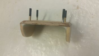
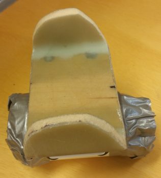
I settled on using my original 1/4″ Finnish Birch plywood mounting base, upside down, with a 1/4″ piece of foam on the top of each end of the wood base. With the foam end pieces in place, it would make a Π shape, only flipped upside down to this symbol shown. If I shaped each end foam piece to allow for the aft leaning GIB seat & the curve of the back of the seat, I could get all the 3 sides to contact the aft side of the GIB seat. I could then flox & glass all these 3 sides (2 vertical, 1 horizontal) to the aft side of the GIB seat for a nice, strong oil heat pump mounting bracket.
After figuring all the above out, I then spent another half hour finalizing the shape of the foam upright that will connect the sides of the 1/4″ plywood plate to the aft side of the lower GIB seat. I used a scrap piece of the urethane foam to dial in the shape, and then once I got the shape set I transferred it to 2 other scrap pieces of foam and cut out the foam end pieces I would use on the actual oil heat pump mounting bracket. To really put all you OCD/anal retentive types into an uncontrollable tailspin, get this: I used one piece of 1/4″ H45 Divinycell foam on one side and a piece of 1/4″ H250 Divinycell foam on the other. I bet that’ll keep you cursing me when you can’t sleep for the next month thinking about it! ha!
I then got my glass all sorted out for glassing the top side of the oil heat pump bracket. I prepregged 2 sets of 3 ply glass using a pair of the gazillion BID triangular pieces you end up with during these builds for each ply of BID. The schedule for the prepreg setups are BID-UNI-BID with the UNI perpendicular to the bottom edge of the side foam pieces. The single ply of BID on the top of the 1/4″ plywood bracket [that I previously floxed the 4 mounting bolts into] is for an initial ply of BID atop this wood base.
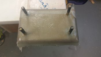
I made up just enough MGS 335 epoxy with fast hardener to glass the 1 ply of BID on top the 1/4″ plywood base. As the layup started to get tacky I then floxed the 2 foam end pieces into place, ensuring their outboard edges were aligned with the sides of the 1/4″ plywood.
Here’s another shot of the oil heat pump mounting bracket. You can see that I taped up the bolts to protect them. Also, up until today I would have called this as the oil pump bracket being upside down, but now it is actually right side up. Also, since I had just a hair of epoxy left over, I went ahead and made up some wet micro and micro’d the inside faces of the foam end pieces.
I then made up some more epoxy with fast hardener and wet out the prepreg setups. You can see I labeled the prepreg setups with arrows so I know the direction of the UNI cloth, which will actually get laid up 90° to how their shown here. I also whipped up some flox, which you can see that I used to put fillets in the corners between the foam and the wood base that I just laid up a ply of BID on top of. At this point, the BID was still very much tacky, but was quickly on it’s way to curing.
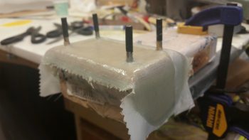
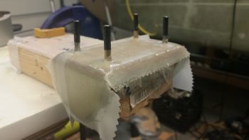
I then laid up the prepregged 3-ply glass setups, 1 on each side and squeegeed out the air in short order with the top prepreg plastic.
I then peel plied the entire top inside glass of the oil heat pump bracket with a piece of 3″ wide peel ply tape. It looks like I added a lot of wet epoxy, but in reality the epoxy was getting really tacky since it was fast hardener, and went it on like syrup vs wet epoxy. It still did its job however in wetting out the peel ply, it just took a bit more “coaxing!”
And yet another shot of the glassed & peel plied top/inside layup of the oil heat pump mounting bracket.
I then took a break to eat dinner and upload a bunch of these pics to this blog. When I returned the laid up oil heat pump glass was cured to at least a good 90% I’d say. I razor trimmed and easily pulled the peel ply and the layups looked good.
Here’s a couple more shots of the cured top/inside glass on the oil heat pump mounting bracket.
I then prepped a 4-ply prepreg setup for the bottom/outside layup for the oil heat pump mounting bracket. The layup schedule for this glass, starting from the bottom ply up was UNI-BID-UNI-BID. Both UNI plies were biased so their fibers ran straight from the top of one side, around the bottom, straight up the other side to provide a nice cradling type strength to the layup.
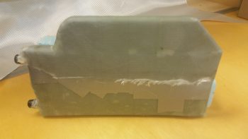
After I glassed the bottom/outside of the oil heat pump mounting bracket, I then of course peel plied it.
Here’s another couple shots of the glassed bottom/outside of the oil heat pump mounting bracket.
By this point in the evening, the heat exchanger top duct layup was cured so I then pulled off the peel ply.
I then removed the whole assembly from the heat exchanger (forcibly!), removed the tape and foam from the inside of the top duct piece, and then quickly trimmed the top duct piece’s edges.
I then set the top duct piece back onto the heat exchanger to test the fit. It looks good and I don’t see any issues at this time. It’s way too late to fire up the Fein saw and trim this duct piece tonight, but I will get it trimmed within the next day or so.
In the amount of time it took me to write all the blathering above, when I went down to check on the oil heat pump mounting bracket bottom/outside glass layup it was cured. So I spent a good 15 min cleaning it up so I could knock it out and include in tonight’s blog.
These pics below kind of make it look like a dead bug, but here’s the cured bottom/outside layup on the oil heat pump bracket.
And here’s another shot of the top/inside of the bracket to see how the two sides came together.
•••
10 July 2017 — Again, the Chapter 22 thing might be throwing you off a bit since it’s electrical, but currently that’s where I have my oil heat system. Thus, any discussion on the major ventilation system in this bird is married to the heat system, and ends up in Chapter 22. Weird huh?! Yep, well, nothing about building Long-EZ’s can be considered normal!
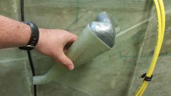
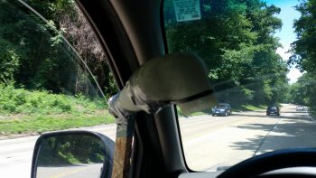
I had to run over to Andrews AFB to scarf up some money out of one bank to transfer to another bank for my upcoming purchase of the GRT EFIS I ordered under the discount that GRT offered for Sun N Fun 2017. Since Andrews requires some Interstate/Freeway/ Motorway driving, I decided to test out my ventilation/heat system ram air inlet. So I drilled a couple of holes into some chip board and then zip tied the inlet to the board. Then I duct taped the zip ties to ensure they wouldn’t slide off.
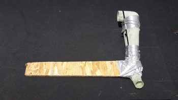
I think it’s ready to go!
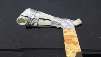
I then tested it out a bit in my driveway to ensure I wouldn’t kill, maim, hurt or embarrass myself . . . or anybody else for that matter.
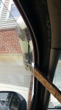
I quickly realized from messing around with it above, that the inlet needed to be straight into the wind as best possible, but the angle for the rest of it really didn’t matter. Regardless (or “Irregardless” for Joe Coraggio!) at around 65 mph I was getting pretty good airflow coming through. But then when I would push my hand up against the outlet I could pretty much shut down the flow.
So, quick assessment is that it seems to have decent airflow, but not good pressure. And in this game sports fans, pressure is what it’s all about. Looks like it’s back to the drawing board on this baby! [Plus, I’ll do some more detailed testing . . . I got some ideas!]
[Operational Note: With the less than stellar performance during testing of this inlet, I have changed my inlet design to remove any bends or angles for air inlet & exit. I’m also moving the actual inlet location from below the strake to the LE of the strake.]
After arriving back home I quickly got into the shop with the intent of getting the 2-ply BID base reinforcement layup for the oil heat pump mounting bracket layup glassed onto the aft side of the GIB seat. I sanded down & prepped the area for the layup.
Then I prepregged 2 plies of BID, measuring 3″ x 8″, and wet it out with MGS 335 and fast hardener.
I then glassed in the 2-ply layup and peel plied it.
Here’s another shot at an angle to help with the exact orientation of this layup.
While the oil heat pump mounting bracket base reinforcement BID curing I then trimmed up the heat exchanger top duct piece.
I then test fitted the heat exchanger top duct piece back on the heat exchanger.
With both top & bottom ducts glassed, I could then verify the exact spots where the heat exchanger top & bottom inlets would go, given their dimensions match the ducts’ dimensions of 0.75″ x 2″.
Again, for better understanding where the heat exchanger ducts are located, I identified them with a couple pieces of paper.
I then took a few minutes to mark up the lines along the entire perimeter edge of the heat exchanger cover to split the case in two and remove the heater core with all its protective tape, etc.

First though, I cut out the heat exchanger duct inlets on both the top & bottom (inlet & outlet).
After a fair amount of pulling, prying and practicing my “How to converse with Sailors” speak . . . and not to forget the requisite injury, I finally got one side off of the heat exchanger core.
Following the shampoo mantra . . . ok, the “repeat” part . . . I was finally able to get the other side pried off as well.
I then got to work deconstructing the protective barrier that Stacey had helped me construct (could this be why it was so difficult to remove?! . . . just kidding!). I took a fair number of pics on this process since I didn’t take any as we applied the protection before.
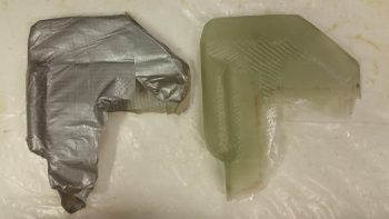
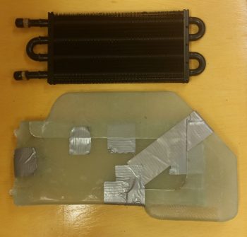
Here’s the final protective tape ensemble with the top & bottom 1/4″ wood caps that all served to protect the heat exchanger core while it was completely covered with glass.

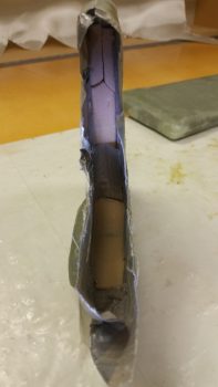
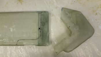
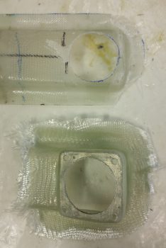
Finally, here’s the heat exchanger core with the two halves of the heat exchanger cover.
I then set the heat exchanger into one of the halves of the cover.

And then checked the fit of the heat exchanger core inside the cover. Ahh, it’s awesome when a plan comes together!
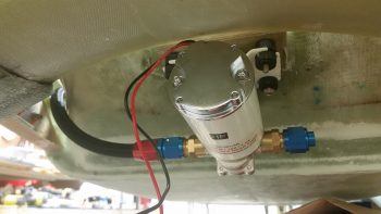
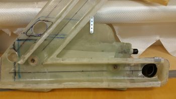
Although I had mounted the oil heat pump to its mounting bracket much earlier in the evening, my last official build task of the evening was to flox and glass the mounting bracket to its location on the lower aft side of the GIB seat.
Before I get into that though, here’s a good shot (aft side) of how the oil heat pump will attach to the mounting bracket.
I pulled off the fittings and taped up the exposed areas of the heat pump as it sat on the mounting bracket. I’m floxing & glassing the mounting bracket into place with the oil heat pump mounted to it to ensure clearance for the pump on both the forward and aft sides.
Although my off-center pic makes it appear more askew than it actually is, I must admit that during the initial mounting process of this thing, it did end up skewed off center about 0.070″ and is higher on one side by about 0.030″ . . . but that’s why we call it the hell hole right?! (As I told Dave Berenholtz: “Loaded up with flox on the edges of course this guy was like trying to balance a fish on a greased hard boiled egg!”)
I do have one more set of BID tapes to do on the bottom after the 2 sets of outboard vertical, 2 sets of inboard vertical, and 1 set of topside horizontal BID tapes cure.
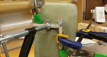
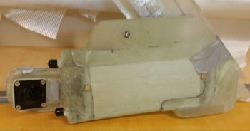
I took this shot at an angle for as good as view as we can get of the side layups, in the hell hole and all!
The layup schedule I used was a 3-ply BID tape on each outboard vertical junction (the foam tabs & seat back), with a 2-ply BID tape on the inboard vertical junctions (inside surface of foam tabs & seat back), and a 3-ply BID tape on the horizontal junction (1/4″ plywood bracket & seat back). Tomorrow, I’ll do a 3-ply BID tape across the bottom intersection with the seat back. Moreover, the 2-ply vertical junctions have a lot of overlap in the interior corners, thus there’s a good amount of “5-ply” BID in the corners.
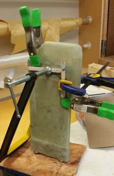
Finally, I wanted to show you all how I secured the pump/bracket assembly in place while I floxed & glassed it up. What you can’t see in this pic is that the wood support is actually sitting atop my large shop vac. In addition, If you look closely you’ll see that I taped 2 stir/ popsicle sticks on the front of the pump as a standoff pad so I could then just feel if it was pressed firmly against the fuselage bottom at the front and then concentrate on the aft side for clearance with the landing gear bow.
•••
11 July 2017 — Today I started out by pulling all the tape off of the oil heat pump and checked the clearances both front and aft. The clearances thankfully looked good. As a side note, with the rubber vibration pads, I can tweak the clearance biased either forward or aft a bit just by the amount of torque I place on each mounting bolt.
I then placed the oil pump fittings back in place, but this time I went ahead and put the AN hose fitting that will go on the end of the oil feed line that heads towards the heat exchanger.
Here’s a shot of the cured and cleaned up oil heat pump mounting bracket.
And another shot.
I then prepregged the next and final round of glass for the oil heat pump mounting bracket installation. I laid up 2-plies of UNI over the edge of each foam upright support tab (after adding micro slurry to the foam and a bit of flox as a transition at the front edge with the seat glass), and then a 2-ply BID tape along the bottom side intersection of the bracket and the back seat (see below).
Here’s the final installed oil heat pump mounting bracket.
In addition to the 2-ply BID tape, I also laid up a 2″ x 2″ 3-ply BID tape in the center area of the bottom side bracket to GIB seat back for a total of 5 plies of BID right in the middle area of the bracket. I couldn’t lay up a more than just the edge on the outer 1″ of each side of the bracket since the bolt studs are in the way (the ones with the black tape in the pic below).
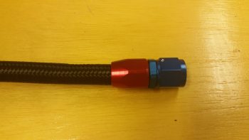
I then got to work building the oil pump to heat exchanger hose, via the 1/2″ to 3/8″ reducer… which this hose will actually attach to. I slid the outer housing of the AN-8 fitting into place until it bottomed out (red piece). The blue tape behind the outer housing was to let me know if the blue fitting piece was pulling the outer housing off the hose more than it should.
I then carefully threaded the blue fitting piece into the red outer housing piece to hand tight at first, then I used a couple of crescent wrenches for the final tightening. Not shown here is the blue tape I wrapped around each component to protect them from getting marred.
I then installed the hose onto the lower reducer fitting in the front left wall bulkhead of the sump tank. I only tightened the fitting hand tight to get a decent idea of the hose length I needed.
I then ran the house into the hell hole through the lowest hole in the GIB seat back. There I cut the hose to length and followed the same process as before to install the opposite end hose fitting for connecting to the oil heat pump.
I then took a bit of time working on the heat exchanger ducts. I trimmed them up a bit at the corner where they intersect and once they were able to play nicely together, I then taped it all up.
I then spent a good 45 minutes figuring out the exact location that the heat exchanger will get installed in the GIB area in the fuselage. I was remiss to take any pics, but I was able to mark up the existing ductwork (that I have yet to permanently install) and the fuselage floor to know where the heat exchanger will get remounted.
Most importantly, for today, I was able to determine how the heat exchanger will get mounted inside its cover, and in turn, how the whole unit will get mounted onto (and atop) the current ductwork.
I was originally thinking I would use spacers, but since the locations I chose for the spacers were about 0.5″ from the center holes on the heat exchanger’s side frames, I chose to simply drill those out for a #10 mounting bolt.
So I drilled out the center mounting hole on the forward end of the exchanger in short order.
And test fitted a bolt.
Then I did the same sequence on the aft end of the heat exchanger.
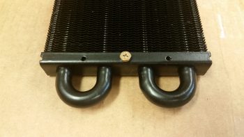
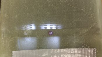
I then remounted the cover onto the heat exchanger, taped up the sides to ensure the heater exchanger was secure, I then shown a light up through one of the holes I had just drilled out in the metal side frame of the heat exchanger and marked it.
I then drilled a hole through both sides off the heat exchanger cover using the hole in the heat exchanger side frame as a guide.
Again, I then test fitted a bolt to ensure the hole was good.
I then did the same sequence on the other end and ended up with another hole going all the way through the heat exchanger and cover.
Here’s the heat exchanger with the mounting bolts (test ones) in place.
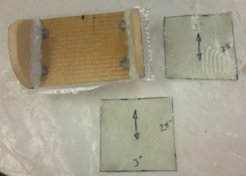
I then cut out some mini air dams from 1/16″ (0.063″) phenolic to keep the air out of the end “caps” of the heat exchanger cover and flowing only through the finned middle area.
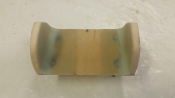
The cover extending over the “U” shaped tubes on each end was glassed that way to make glassing the cover over the heat exchanger much easier. On the front side (shown below) it also created a straight wall to use as one of the interior duct walls for the exit duct of the heat exchanger. Finally, it simplifies the heat exchanger lines and in my opinion makes it look better. Still, there’s no need for the air to get “lost” in those end “cap” areas so I’m keeping the air path focused so that it will run only through the fins, which are kept warm by the hot oil running through the pipes.
[As a side note, you can see the blue dot close to the hole I drilled in the frame of the heat exchanger. That blue dot was where I had planned on putting a spacer for mounting but obviously decided against it.]
This pic is a little bit washed out, but you can make out the mini air dams at each corner of the heat exchanger.
I then prepped the outboard wall of the heat exchanger cover by sanding the strips that would mate up to the frames on each side of the finned core.
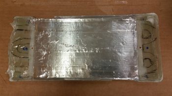
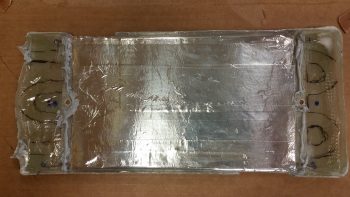
I then cut strips of foil tape and placed them on the inside of the heat exchanger to keep the heat as concentrated in that center area as possible as the air flows through it.
I then did one last test fit to ensure all my parts were good and aligned for what was next…
. . . hi-temp RTV.
I ran beads of the hi-temp RTV along the areas I sanded that would mate up with the frame of the heat exchanger. I also put a small bit around the contoured openings for the fitting posts.
Then, using installed bolts through the mounting holes as guides, I placed the heat exchanger in place onto the beads of hi-temp RTV. I added a good dab of hi-temp RTV at each outside corner of the heat exchanger and set the mini air dams in place, and then ran a bead along the edges of each dam to hold it in place.
I then RTV’d the top of the heat exchanger edge frame, a thin bead along the top of each phenolic mini air dam, and again a small bit around the contoured openings for the fitting posts on the opposite side.
I then set the other side of the heat exchanger cover into place to entomb the heat exchanger once more. I then taped the 2 halves of the cover tightly on each of the 4 sides of the heat exchanger. I then placed the entire unit on a plastic box, added a bunch of drills and heavy batteries to weight it all down in place, and then ran to the store to buy a few groceries I needed!
Upon my return, I had a quick dinner before heading back down to the shop. In all, I let the hi-temp RTV cure a little over an hour total as I also cut the BID for the prepreg setups in prep for the initial glassing of the 2 cover halves back together over & around the heat exchanger.
I used only 1 ply of BID in prepreg setups, all 1″ wide. Since there are some minor gaps that are understandably much wider if no pressure is placed holding the two sides together, I decided to make this a 2, possibly 3, step process (the extra one may be needed for the corners).
I taped a tight band of duct tape around each duct opening which worked well to keep the forward end (top in pics below) and middle sections tightly together. I did need to use another bit of tape on the corners to close the gap at the bottom side in the pics below (which is the aft side of the heat exchanger).
I then laid up all the glass strips and peel plied them.
•••
12 July 2017 — I actually went down last night after I finished yesterday’s post to pull peel ply and razor trim the first round of layups that secure the heat exchanger halves back together, with the heater core secured inside. Except for the corners, which I basically just trimmed away, all the layups looked fine. Here’s a shot of the top edge.
Here’s a shot of the inlet on the top side of the heat exchanger. It still needs just a bit of cleanup on the edges, but beyond that I’m pleased with how the heat exchanger is coming along.
Here’s the bottom side of the heat exchanger.
•••
13 July 2017 — Today I glassed round 2 of securing the halves of the heat exchanger back together. I started by simply filling in the 2″ gaps created by the duct tape that I used to hold the 2 sides together tightly. Again, I used 1 ply of BID as I did before.
I then glassed a small patch of BID on each forward corner (top side in pics below).
Finally, for this round I went to the aft side and laid up a small 1-ply BID patch just outside of the AN fitting posts on the corners (bottom in pics below).
I then peel plied all these small layups.
Later in the evening I pulled peel ply from the layups and cleaned up the layups.
•••
15 July 2017 — Today I mocked up the upper & lower heat exchanger ducts after my design, placement, and initial construction of the heat restrictor valve (butterfly style) that resides towards the aft end of the heat exchanger inlet duct.
I would have preferred to have the heat restrictor valve located about 1-1/2″ forward, where you may be able to see a location dot. However, since I wanted the valve’s actuator arm on the outboard side of the heat exchanger unit for clearance to keep it from hitting the GIB’s knee or leg when the valve is actuated, I had to place it a bit aft of where I wanted (where it is in the pic below) to allow for valve actuator arm clearance with the underlying (outboard, on the cockpit wall) ductwork.
I then laid up 4 more small pieces of BID on the aft side of the heat exchanger to finalize the sealing up of the heat exchanger cover. In addition, I added a 1-ply BID “patch” on each side of the heat exchanger upper inlet duct around the heat restrictor valve mounting holes (seen on the right side in the pic below).
•••
16 July 2017 — Today I spent about 45 min pulling the peel ply from both the aft end layups of the heat exchanger and side reinforcement ply of BID layups on the upper/inlet duct.
And on cleaning up the peel ply strings and the edges of each layup on both sets of layups.
The heat exchanger needs a good sanding to smooth out all these mini-layups, but beyond that I’m done with the mechanical resealing of the heat exchanger.
•••
17 July 2017 — Today I started on the oil heat system by laying up a ply of BID to seal the cut angled edge of the heat exchanger lower duct piece. This edge was one that I had to cut to remove the duct piece off to the heat exchanger cover. I then peel plied it.
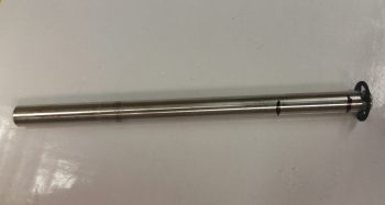
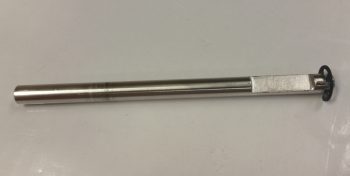
In addition, I also mounted the two 1/2″ oil heat lines that terminate into the reducers mounted into the left side bulkhead that is an extension of the GIB thigh support fuel sump front wall (no pics). There’s not a lot of space to get in there to mount the oil line fittings, so it took a bit of time to get them installed. I still plan on making a specialized wrench that will better allow me to install & remove these 1/2″ oil lines due to this limited space.
By the time I finished riveting the nutplates onto the GIB charger & installing the oil lines, the layup on the heat exchanger lower duct piece was cured enough that I pulled the peel ply & cleaned it up. I then “mounted” it on the heat exchanger, positioned it in place where it will be mounted in the cockpit, and then drilled a hole through the aft heat exchanger mounting hole into the lower horizontal duct that sits immediately behind (outboard) of the heat exchanger.
I then removed the ductwork and sanded down a 2″ wide swath from the top edge of the lower duct flange to the bottom flange edge, with the mounting hole in the center (1″ mark) of the sanded swath.
Here’s a wider angle shot.
I then laid up a 2″ wide ply of BID from the top edge of the horizontal duct flange to the bottom flange edge for reinforcement when the heat exchanger is mounted. For a little extra strength, I also laid up a second ply of BID 1.5″ wide that terminated on the bottom and top edge of the actual duct (not the flanges). I then peel plied the layup.
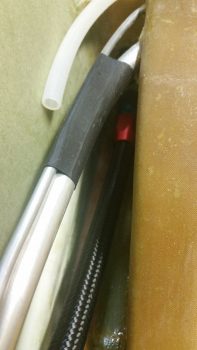
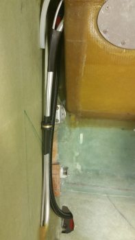
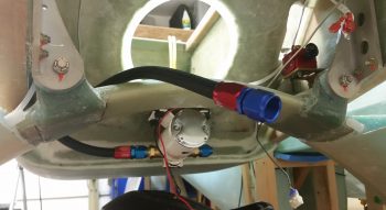
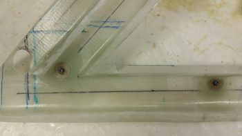
Here’s a pic of not only the left GIB armrest forward mounting bracket floxed in place, but also the two 1/2″ oil heat lines that I mounted earlier.
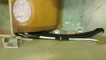
Here’s a shot of the oil feed line that I previously mounted that comes out of the oil pump and to the heat exchanger via the 1/2″ to 3/8″ reducer. In the foreground you can see the oil return line that comes from the heat exchanger back to the engine oil sump. I terminated this oil return line hose with the AN-8 fitting just prior to taking this pic.
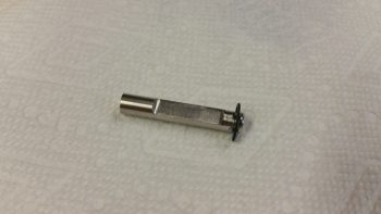
My final task of the evening was working on the heat exchanger upper inlet duct’s restrictor (butterfly) valve. I started off by redrilling the valve mounting holes that I had covered up with the reinforcement plies of BID, then inserting the valve plate’s mounting rod into the duct holes and marking the sidewall positions onto the rod.
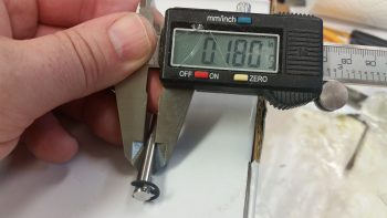
I then Dremeled and filed a flat spot almost 1/16″ (0.060″) deep into the valve plate’s mounting rod specifically to mount the valve plate to.
The diameter of the valve rod is 0.240″.
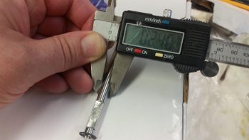
And as you can see, the width of the rod after I cut nearly 1/16″ of it out, is 0.180″. Makes sense eh?
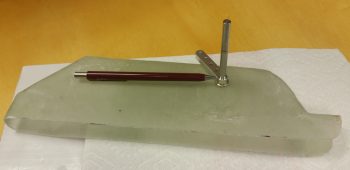
Here is the valve rod installed in the duct with the valve plate mounting flat showing. As you can see, I need to make the flat a little wider so that the edges of the valve plate sit flush with the duct sidewalls.
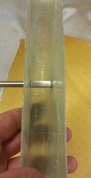
I’ve left the heat restrictor valve rod long for now, but will be cutting it to length in the next day or two after I’ve worked out & finalized all the other working valve dimensions. It will most likely get cut at the spot where the tip of the pencil is pointing to.
The side shown below is the outboard side, so as I mentioned before the valve lever will operate “behind” the heat exchanger and away from any body parts of the delicate GIBs! ha!
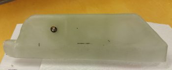
Here’s the inboard side of the heat exchanger, with the restraining E-clip showing on the inboard end of the heat restrictor valve rod.
•••
18 July 2017 — First off, let’s revisit the phases I identified a while back for finishing up the oil heat & fresh air system. Here’s the current status of those phases using stoplight colors:
- Phase I – Ductwork glassed
- Phase II – Heat exchanger glassed
- Phase III – Ductwork interface holes drilled and valves built
- Phase IV – Ductwork installed with heat exchanger and valves in place
- Phase V – Oil pump installed & oil lines run
- Phase VI – Pilot seat area ductwork constructed and installed
- Phase VII – Instrument panel forward ductwork constructed and installed
- Phase VIII – Valve cables terminated and handles installed
I started out today by pulling the peel ply and cleaned up the 2-ply BID reinforcement layup on the lower horizontal duct for the aft mounting bolt of the heat exchanger.
I then prepped the inside of the horizontal duct for floxing in an EZ Point nut by sanding the area right around the mounting hole.
I then floxed and glassed an EZ Point nut into place and then peel plied the layup.
I then pulled out the Dremel Tool and widened the notched flat on the 1/4″ heat restrictor butterfly valve rod.
After the EZ Point nut layup cured, I cleaned up the layup and then mounted the heat exchanger at its aft mounting hole onto the EZ Point hardpoint.
With the aft mounting bolt in place, I was then able to locate the forward heat exchanger mounting hole position.
I marked the position of the forward mounting bolt and then removed both the heat exchanger and the underlying ductwork. I then drilled the forward mounting bolt hole and remounted the heat exchanger back onto the ducts.
I then ensured the lower duct on the heat exchanger was positioned correctly to further allow me to mark the transition hole that allows the warm air to flow from the heat exchanger’s lower duct back into the duct network.
I then drilled & shaped the duct air transition hole.
Here’s a closer shot of the air transition hole from the heat exchanger’s lower duct into the duct network
I then prepped the glass around the forward heat exchanger mounting hole on the ductwork assembly and laid up 2 plies of BID to reinforce the duct network when the heat exchanger is mounted to the face of it.
I then assessed the airflow through the heat exchanger lower duct (outlet) and decided to glass a dam in the top side of it where the air transition hole mates up to the ductwork network to keep the air from getting trapped in the top corner above the transition hole.
I used a taped piece of foam as the form for the dam and laid up 1 ply of BID for the dam wall.
I laid up the glass a tad wet primarily since the form and glass wasn’t solidly in place, and since I covered it with a more refined micro “ramp” shown below.
Here’s the ramp that I micro’d in place in the heat exchanger lower duct (outlet). I waited until the layup above was tacky, whipped up some micro and then formed the micro ramp.
I then set my sights on the heat restrictor (butterfly) valve by marking the valve rod for cutting.
I then cut the 1/4″ butterfly valve rod to length.
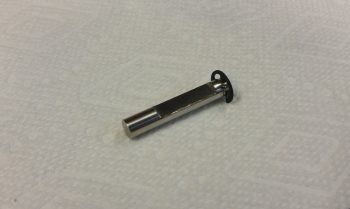
I then test fitted the cut 1/4″ butterfly valve rod with the valve lever in place as well. The pic below shows the outboard side of the heat exchanger’s upper (inlet) duct.
And here’s a shot of the inboard side of the heat exchanger’s upper (inlet) duct.
•••
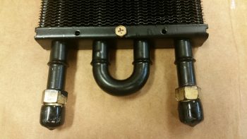
19 July 2017 — First off, I thought I would show you a couple good shots of the EZ Point Locking Nut that I’m using to attach the heat exchanger to the duct network along the lower horizontal duct.
Today I started off by sanding the interior surface of the glass at the entrance to the GIB high air duct in prep for attaching the forward EZ Point nut that will be used in concert with the aft EZ Point nut to secure the heat exchanger to the duct network. I then floxed in and glassed over the forward EZ Point nut with 1 ply of BID.
I then peel plied the forward EZ Nut Point 1-ply BID layup.
I had to run up north to help some friends that are moving out of the area here in a couple of weeks. When I returned back home I pulled the peel ply off the forward EZ Point nut layup and cleaned it up. Here’s a shot of both installed/glassed-in EZ Point nuts along the lower side of the duct network for mounting the heat exchanger.

Here’s the same shot from the inside of the duct network.
I then did some final preps for floxing the lower outlet duct onto the heat exchanger to meld these two components together permanently.
I then whipped up some flox and floxed the lower outlet duct onto the heat exchanger. I then clamped the lower outlet duct into place on the heat exchanger.
Here’s a closer shot.
I then headed up north again to help out my friends, and upon my return I removed the clamps and cleaned up the seam of the floxed-on lower outlet duct.

•••
20 July 2017 — My goal today was to get the GIB low air eyeball vent base glassed up, which I’m happy to report I was able to accomplish.
I started out today by marking the aft end of the horizontal duct (which is upside down in the pic below, and subsequent pics . . . just think of it as how you would you view it when looking into the GIB area from the left side of the plane down) with a 1-3/4″ diameter circle to drill it out with the same diameter hole saw.
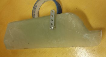
I forgot to take a pic of the hole after I drilled it out, but it came out fine. I then measured out, cut and shaped a piece of urethane foam for the base of the eyeball vent. I then taped up the foam and surrounding duct to create a form for the lower GIB eyeball vent base. As you can see, the base is angled towards the front of the plane in order to warm up the feet area of the GIB.
I then drilled a 1-3/4″ hole in my German 0.5mm aluminum sheet and then cut out a 2.1″ x 2.1″ piece centered on the hole. This aluminum piece will serve as reinforcement for the eyeball vent assembly. I then sanded the aluminum reinforcement piece to texture it for a better grip with the epoxy & flox.
I then laid up 1 ply of BID over the taped form before wet-floxing on the aluminum reinforcement piece. I then laid up 2 more plies of BID over the aluminum reinforcement piece and the first ply of BID.
This was a bit of a complex layup with all the angles, so to keep the top flat I weighed it down with a taped 2×4, and then lightly clamped that in place as well.
I worked on the heat exchanger top duct butterfly valve plate that I cut out of 2024 aluminum (sorry, no pics) and after a bit of filing it down I finally got it to fit in both the upper inlet duct & the notched flat on the 1/4″ butterfly valve rod. However, when I went to drill the holes through both the butterfly valve plate and the rod, I realized after about a half hour of drilling into the rod that my stainless steel bit was not, in fact, working well.
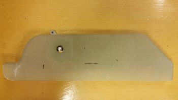
By the time I got done unsuccessfully messing around with drilling the butterfly valve rod, the glassed eyeball vent base was cured. I pulled the weighted board off the top.
And then redrilled the 1-3/4″ hole for the eyeball vent.
I then set the eyeball vent in place in the freshly glassed base.
As you can see below, I used the eyeball vent assembly as a guide to drill out the 4 corner mounting holes into the glass and reinforcement layer of aluminum on the vent base. I then cleaned out the foam inside that made up the form and gave the cured layup a quick trim.
And then pulled the eyeball vent base off of the end of the horizontal duct.
I then quickly checked the fit by placing it back on the duct without the tape. It fit fine.
I also marked the raw eyeball vent base for trimming.
And trimmed ‘er up with the Fein saw. I then set the vent base back on the duct.
Here’s another shot of the vent base placed onto the duct.
I then mocked up the eyeball vent.
Here’s a shot showing the interior clearance with the eyeball vent in place.
I mounted the eyeball vent into place in the vent base using 4 screws & nuts.
I then mocked up the eyeball vent & base along with the heat exchanger mounted to the duct network. As you can see, I also terminated the fittings for the oil line hoses that run from the left front wall thigh support fuel sump bulkhead to the heat exchanger.
Here’s a closer shot of the GIB lower vent that I just glassed & configured tonight with the heat exchanger and oil lines in place. I will assess, and most likely move, the eyeball vent (and base) about 1/4″ to 1/2″ forward towards the heat exchanger for better clearance with the oil lines.
In addition, the actual lengths of oil line hose used was about 4″ and 4.5″ for the respective hoses. In other words, not much as far as the thinner 3/8″ lines go.

•••
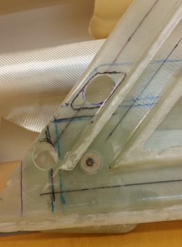
21 July 2017 — I started off today by figuring out where my heat exchanger air will enter from the main air duct into the upper heat exchanger duct . . . which of course is the inlet duct for the heat exchanger. After figuring out where my perimeter “no-go” areas were for both the main air duct and the underlying upper/inlet duct [as it’s positioned in this pic…look upper left] I marked off the inlet hole.
I then drilled the center mass of the marked hole out with a 1-1/4″ hole saw bit.

I then used a sanding drum on my drill to shape the rest of the hole. This inlet hole is a fair bit larger than the rest of my standard sized 1.5″ duct area since with the height of the duct at only 0.75″ tall, the air inlet ramp created by the opened valve –to divert the incoming air into the heat exchanger– will be longer and flatter, requiring a bit more open hole area for the equivalent amount of air to flow through.
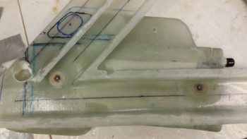
Here’s a shot of my current left side wall mounted GIB area ductwork, with the heat exchanger and the GIB low eyeball vent mounted as well. If you look closely, you may note that I chopped off 0.4″ of the aft end of the horizontal duct (bottom right of pic), and moved the hole forward 0.4″ to allow moving the low eyeball vent forward for clearance with the 2 oil lines.
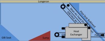
Also, for a bit better understanding of what I’m doing here, I took the pic above and turned it into a quick labeled diagram of all the major parts of the ductwork & oil heat system located in the GIB compartment. Yes, it’s not the best graphic…. and not to sound overly snarky, but my goal is to get this airplane finished, not to build stunningly beautiful charts!
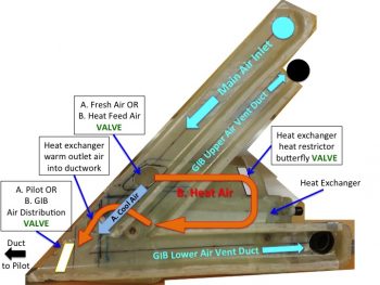
Below is a closeup shot of the 2 heat exchanger-related holes in the main air inlet duct. The top one is the one I just created, and again which allows the outside ram air to flow through the main inlet duct and into the heat exchanger –WHEN THE HEAT AIR VALVE IS OPENED. Otherwise, if the valve is closed the air simply passes over the valve and continues on its merry way into the ductwork both in the GIB area and forward to the pilot’s seat area.
The lower opening is strictly used only when the air is flowing through the heat exchanger and is the inlet for warm air to flow from the heat exchanger into the ductwork system. An important note is that the valve that diverts the air to the heat exchanger lies in-between these 2 openings. Thus, when the valve is open and the air is flowing into the upper opening, it stops any air (or the vast majority of it) from passing into both the rest of the ductwork system (since it’s being diverted into the heat exchanger) or into the lower opening (which will have warm air exiting out of it from the heat exchanger into the ductwork).
You might be wondering about the lower air opening when the heat exchanger is not being used for heat, or stated another way, is not in the “on” state.
Well, some air will certainly flow into the heat exchanger in the opposite direction through this lower hole. First, the hole in the main air inlet duct (on the left side) will be covered by the valve plate so no air can flow backwards into the main air duct from the heat exchanger. Then, if you look below you’ll see a bright shiny lever on the side of the heat exchanger’s upper duct, which is the inlet air duct from the upper hole to the heat exchanger. This lever controls the heat restrictor butterfly valve. When the heat exchanger is not being employed to produce heat, this valve is closed, and thus also restricts any air from passing in the reverse direction through the heat exchanger.
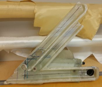
Here’s a shot of what the GIB is more likely to see sitting in the back seat. This is a good shot of how the heat exchanger will look in its final constructed state. I just floxed the lower outlet duct (on the right) onto the heat exchanger. Once I finish constructing the butterfly valve (I just ordered a 1/4″ 2024 rod from ACS) I will also flox the upper inlet duct into place atop the heat exchanger. On the left side of the pic you can of course see the GIB lower eyeball air vent.
I then started work on prepping the main air duct glass for mounting the Fresh Cool Air OR Heat Feed Air Valve into place (I’m going to have to come up with a standard name for these valves!). I sanded the interior duct glass where yet another 0.5mm aluminum reinforcement plate will be glassed in for mounting the valve assembly.
I cut out the 0.5mm piece of aluminum (from my German consumables stock!) for my reinforcement plate and then wet floxed it into place with one ply of BID over it.
 Although I had made up a minuscule amount of epoxy for the layup above, I still had a decent bit left over. So I quickly moved onto my next layup –earlier than I had planned– and laid up 1 ply of BID on the opposite side of the aluminum reinforcement plate, this ply of BID also glassed in place merely for reinforcement purposes.
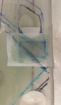
After a few hours my glass had cured on the valve mounting reinforcement layups, so I pulled the peel ply and cleaned them up. I then spaced out & drilled 6 holes for countersunk rivets through the lower valve assembly plate and duct wall. I then floxed the lower valve assembly plate into place and riveted the 6 rivets into place.
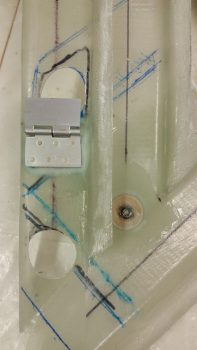
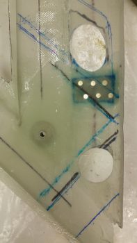
•••
22 July 2017 — I started out today by buying and then swapping out the GIB lower eyeball vent mounting screws to stainless steel hex buttonhead screws. The other ones worked fine, but they were just too industrial looking for my taste, Yes, minor point, but might as well make it all look nice, eh?
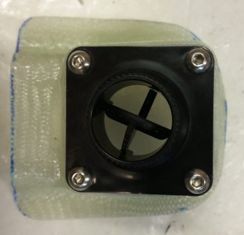
Here’s the another inside shot of the GIB lower eyeball vent mounting screws.
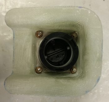
After sanding down and prepping all the mating surfaces, I then whipped up some wet flox and floxed in place the GIB lower eyeball vent & base to the lower horizontal duct.
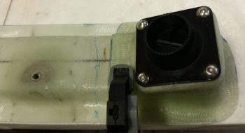
About 8 hours later I pulled off the clamp and cleaned up the minor bit of flox that had oozed out.
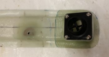
The flox spread was nice and uniform, meaning this GIB lower eyeball vent mounting to the lower duct was a success.
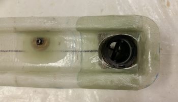
•••
24 July 2017 — As far as building, today was one of those kluge days from hell….
I’m still not feeling 100%… it’s really hot here… and unexpected mishaps have reared their ugly heads again: specifically, on the heat exchanger upper inlet duct heat restrictor butterfly valve. As you can see below, I have the butterfly valve on top with the 2 drilled holes (I finished the 2nd one tonight), then the first stainless steel rod which proved virtually impossible to drill, then at the bottom the converted drift pin that I handily snapped off the 4-40 tap in the second and last hole . . . After repeated attempts to remove the snapped off tap piece, including knocking it out from the opposite side with a hammer, I was left with only a bent, misaligned butterly valve rod.
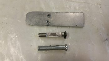
So I digressed and did a fair amount of research on different components and upcoming build tasks. I then went out and picked up another 4-40 tap set and a couple of large grommets. Upon returning home, I tested out a grommet in the fresh-cool/heat air transfer vent hole. Amazingly, in light of the total SNAFU with tapping the butterfly valve rod above, the grommet fit in the odd shaped hole perfectly!
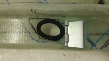
Below is another shot of the grommet more from the side. You may note that I cut the grommet to taper down towards the top side (left in pic) and then sanded it to smooth it out flat.
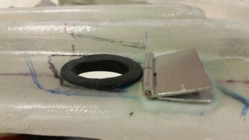
I then drew up a cardboard template for the actual fresh-cool/heat air valve plate and then transferred that over to a piece of 1/16″ 2024 aluminum, which I then cut out. The valve plate is curved on the top left corner to seal asl best possible with the PIC seat back corner. It’s also curved on the lower right corner to seal up that curved corner as well.
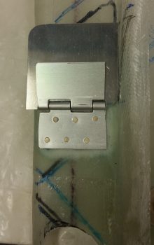
Here is the fresh-cool/heat air valve plate and the rubber vent hole grommet from the opposite (inboard) side. In the center of the valve plate showing here is where the valve actuation control arm will get mounted. This will be the control arm that when the lever is moved forward or aft at the pilot’s station, the fresh-cool/heat air valve will be opened or closed for either cockpit cool ventilation air or cockpit heat.
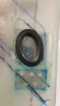
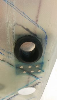
•••
25 July 2017 — Today I started off by heading out to my local hardware store to buy another clevis pin to be converted into my heat restrictor butterfly rod (round 2!) and some other miscellaneous hardware.
Last night I already bought another 4-40 tap set to replace the one I broke. I also looked for the same style clevis pin that I am converting for the butterfly valve rod, but none of them at Lowe’s or Home Depot, which were the only stores open, would work.
Upon returning home, I then floxed into place the rubber grommet that I configured to go in the hole between the main duct outlet into the heat exchanger’s upper duct (heating air inlet).
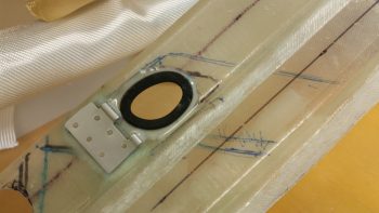
Here’s the backside of that same grommet. This is the surface of the grommet that will actually interface with the gasket that I place around the matching hole in the heat exchanger’s upper/inlet duct (see below).
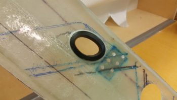
I had pondered a while last night and this morning on how to fill in the minor gaps between the heat exchanger duct entry & exit holes and the associated holes in the main duct. I mounted the heat exchanger on its ductwork mounts and assessed the widths of grommets and/or gaskets (which I stumbled across during my pondering) that would be required.
I decided on using gaskets to mate up with the grommets I had just floxed into place. [Actually, I cut out this gasket below for the heat exchanger upper duct and floxed it in place at the same time as the grommet above.]
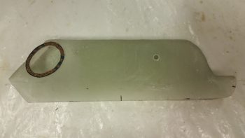
I also went ahead and floxed an AN960-416 1/4″ ID washer in place to use as a reinforcement sleeve for the heat restrictor butterfly valve.
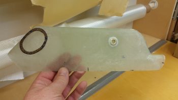
A bit later I floxed on 1.5 gasket rings on the outlet hole on the heat exchanger’s lower duct. I floxed in place one entire gasket ring first, then a half of one shaped basically in a backwards “C” in relation to the pic below.
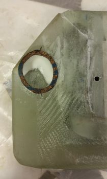
When I floxed in the gaskets above, I also floxed in the 1/4″ washer on the other side of the heat exchanger’s upper/inlet duct.
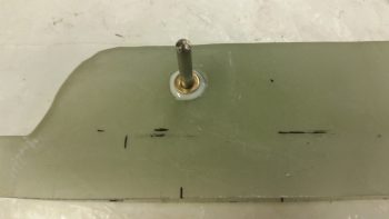
The vast majority of the day was spent on constructing the heat exchanger’s upper duct heat restrictor butterfly valve. After snapping my 4-40 tap off in modified clevis pin #1 (which was heat restrictor valve rod #2), I vowed to go super slow and clear the tap at every step this go-around. Well, I got half way through the 2nd hole and wouldn’t you know it: my new 4-40 tap snapped in half! Oh yeah, and this time I was fortunate enough to impale myself on the top of my thumb! Ugh!
Well, after about 15 minutes I was finally able (and fortunate enough!) to remove the snapped off tap piece. I then very carefully was able to use the two broken tap pieces to thread just enough of the remaining hole to mount a screw into it.
Later on, in the same hole –after using countersunk screws all day and well into the evening– as soon as I switched to my new standard stainless steel phillips head screws, the head snapped off immediately as I was just finalizing threading it into place. Ugh!
After another 30-40 minutes of drilling out the snapped off screw, I was again thankful that the slightly undersized drill bit that I used didn’t wipe out my threads in that hole. Going back to my CS screws seemed to do the trick and was definitely the safe option at this point.
Instead of taking a myriad of pics (which I failed to do anyway amidst all the mayhem!), I decided that I could better explain what I was doing with a video… so here you go:
•••
26 July 2017 — Today I started off by Alodining the cooling/heating air valve plate.
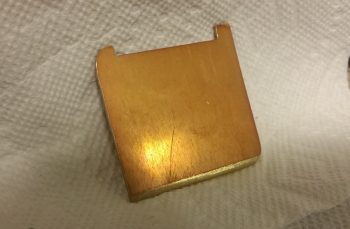
And Alodining the heat restrictor valve (butterfly) plate.
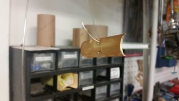
I then installed the heat restrictor valve (butterfly) plate (note the 2 new standard screws used to install the plate).
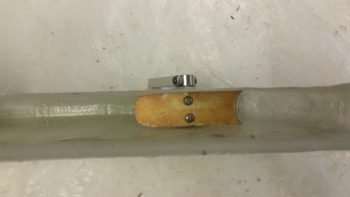
I then mounted the upper/inlet duct to the heat exchanger body using RTV silicone. I used RTV to make it easier to remove the upper/inlet duct if required in the future to tweak or repair the heat restrictor valve.
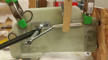
A few hours later I removed the clamps and cleaned up the excess RTV silicone from the upper duct attachment. In addition, I floxed a Clickbond in place for the heat restrictor valve control cable Adel clamp.
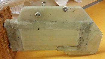
•••
27 July 2017 — Today I laid up a ply of BID over the Clickbond I floxed into place last night onto the heat exchanger’s upper duct, to be used for an Adel clamp to secure the heat restrictor valve cable in place. I peel plied that layup, and below is a shot after it cured and I pulled the peel ply.
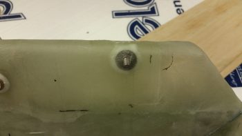
I then attached an Adel clamp to ensure the fit & finish was right… so far, so good!
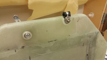
•••
11 August 2017 — I don’t have any pics showing my progress, but today I actually determined the size and shape of the valve lever arm for the heating/air system. This valve is the one that will determine whether incoming fresh air is left alone to be routed through the ducts for cooling air, or diverted to the heat exchanger for heating air. I cut out, shaped and cleaned up the pieces to ready them for install via flush-mounted rivets. I was getting ready to drill the holes for my rivets when a buddy called and I ended up meeting him out for dinner and a couple beers. So… I’ll get some pics of my heating/air valve work tomorrow.
•••
12 August 2017 — I started out today by cleaning up the inboard face of the heat exchanger by sanding the edges of the added upper & lower ducts where they overlap onto the main assembly.
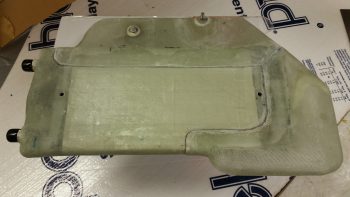
I then cleaned up & prepped the heat exchanger for glass, or actually for 1 ply of carbon fiber.
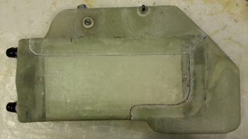
Here’s the ply of carbon fiber after I laid it up and peel plied the edges a bit to ensure it stayed in place. I didn’t go with the traditional super sexy carbon fiber look, since the reason I’m adding the carbon is I believe that with this heat exchanger being inboard of the ducts, it will get rubbed on with legs, knees, small marsupials, etc. over the years. If it was painted, as I’ve seen with many a canard, over time the paint would simply rub off. I wanted something that would not only be a good contrast with the gray granite paint that I’m using for the cabin, but that would be hardy enough that it would withstand getting rubbed on over the years without discoloration or deterioration of the surface.
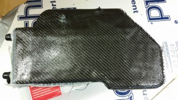
I used fast hardener so a few hours later I trimmed the carbon fiber and got the heat exchanger pretty much back to the way it was before, just with a ply of carbon fiber on the face of it.
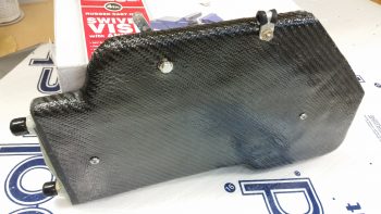
I wasn’t sure what I was going to do with the aft end, I just knew I didn’t want to attempt making my layup infinitely more difficult by trying to put carbon fiber here and wrap it around. Admittedly, my original plan was to get much closer to the edge but the carbon fiber apparently had other thoughts on the matter.
With so much stuff to get done on this plane, I punted and went with the 80% solution to get this thing in the done column, and simply painted the aft end . . . In the grand scheme of things I don’t think anyone will really notice that the aft “face” is painted black.
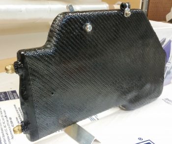
I then got to work on the fresh air/heating air routing valve. Below is the valve assembly in its component parts, ready for assembly.
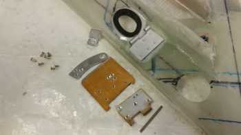
And here’s after I riveted it all together . . . the second time!! You see, the valve hinge had to go in first before I riveted all the main pieces together. So of course I went to Tahiti for a few minutes in my mind while I riveted the first couple of rivets to get it all together. My fault, but what a royal PITA to drill those rivets out. Plus, it widened the holes a bit so I used a bit longer rivets and merely mashed harder!
Ok, so she ain’t perfect, but it looks like this dog will hunt. The one thing I’m not overly happy with is the height of my valve, since it’s taking up valuable space in my duct and reducing the duct’s cross section for airflow by almost 0.5″.
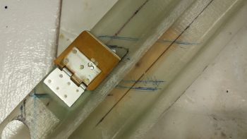
Here’s a shot to see where this valve is in relation to everything else.
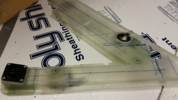
And here’s a few shots of the valve and the attached control arm.
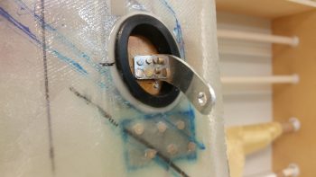
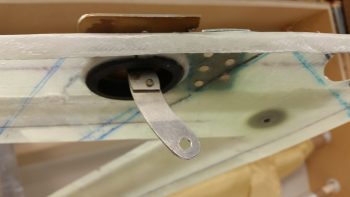
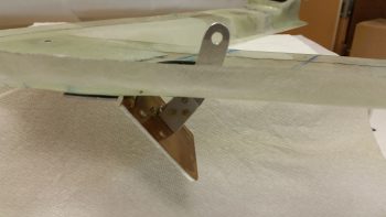
I then added a cable mount bolt and a cable to test out the function of the valve. It’s simple and I don’t think there should be any issues (besides having to trim down the upper edge of the valve since it’s just a hair wide.)
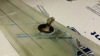
•••
15 August 2017 — Today I took a piece of urethane foam and shaped it to create an exit duct out of the top of the main duct that moves the air to the GIB upper duct vent. I cut a piece of 1.25″ diameter 6061 tubing that I ordered specifically for these ducts… mainly because that’s the diameter of the eyeball air vents that I have on hand. In addition, I also ordered some Skeet tubing as well, but it’s on back order with ACS.
I then prepped the foam for glass using duct tape. I of course left the 6061 tubing clear since it will become an integral part of the upper duct vent transition.
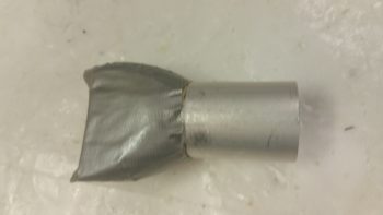
Since the air will curve a bit “up” (all relative here) coming out of the duct, unlike the lower GIB duct vent, I decided to create 4 sides to the duct transition (transition from the fiberglass duct to Skeet tubing and then to the eyeball air vent) so I needed to get the “bottom” of the duct transition glassed first. Thus, I glassed the bottom with 1 ply of BID and peel plied it.
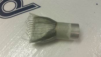
After the BID cured I pulled the peel ply.
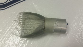
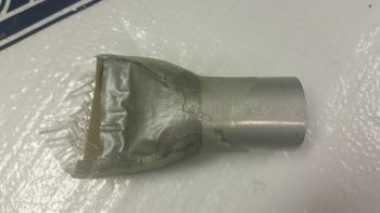
And then trimmed the glass.
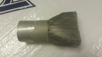
Here you can see both sides of the upper duct transition vent.
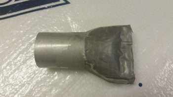
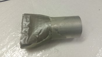
I then set the initially-glassed duct transition vent in place in the top of the main duct channel and taped it up in prep for final glassing.
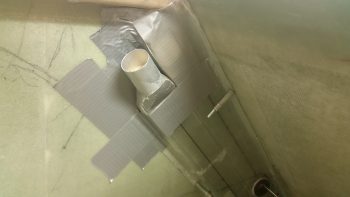
I then laid up a small ply of BID just over the top of the foam piece area (taped) for strength, and then laid up a ply of UNI and a ply of BID to create an overlapping flange on the existing duct. I of course could have created the entire duct transition piece to fit inside the main duct channel, but I wanted to optimize airflow as much as possible.
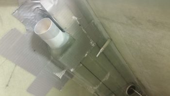
And here’s a bigger picture view of the GIB upper duct vent transition and the rest of the duct network. If you’re thinking maybe the duct transition piece is a bit too high, you may be right. But I’ll be able to adjust the height through trimming down the aluminum tube length and/or hacking off some of the main vent channel if need be.
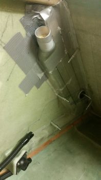
Here’s a bit clearer shot of the fresh air / heater air valve with the control arm clearly visible.
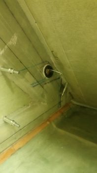
•••
16 August 2017 — I started out today by pulling the GIB duct transition for the upper vent off the tape form and marking it for trimming.
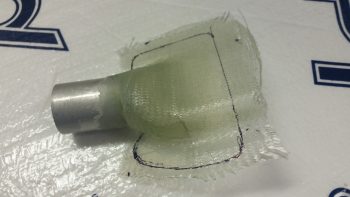
I then trimmed it with the Fein saw.
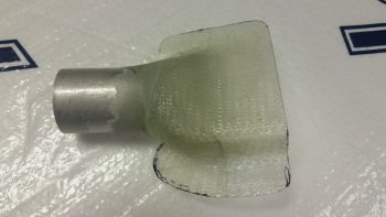
Here’s the underside of the GIB duct transition for the upper vent.
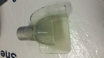
And the view from the rectangular sidewall duct heading into the vent tube transition.
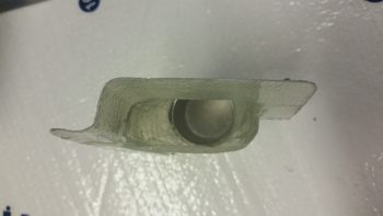
Here it is set in place on the sidewall duct. Again, I’ll be able to tweak its final position as I install the vent sidewall console.
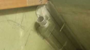
Keeping on the duct theme, I then marked the position of where the duct traverses the pilot seat back in the lower left corner. I then drilled 4 pilot holes for the corners of the rectangular duct hole.
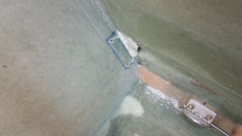
I got the front side glass cut out using the Fein saw, then razor knife & then removed the foam.
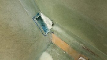
I then cut out the aft side glass, cleaned up the hole and micro’d the edges.
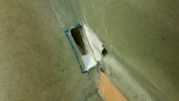
I then was finally able to get around to cutting the slot in the forward end of the Heat Exchanger inlet duct for the fresh-cool-air/heater-air valve control arm. I then mocked up the heat exchanger mounted inside the GIB area with the air ductwork in place. Also note that I have the upper GIB vent duct transition in place as well.
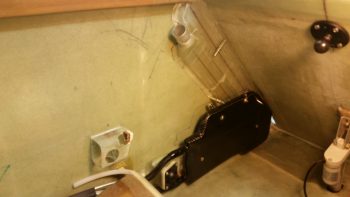
Here’s a closer shot of the oil heater heat exchanger.
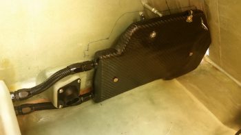
I then wanted to get a shot showing how thin my entire ductwork and heat exchanger mounting is. Of course, here I have to give a shout out to Nick Ugolini for R&D’ing the appropriate thin-line roll-your-own ducts.

•••
27 August 2017 — Today, since my next task required the dismantling of the mocked up heat exchanger and duct system, I decided to knock out the next oil heat system video that I had promised to do a while back . . . so here it is:
•••
3 September 2017 — First off, I sealed off the significant gap between the fresh air/heater air valve (Valve #1) plate and the duct sidewall. I taped off the valve plate with brown packing tape (I’m out of clear) and kept the valve plate up flush to what will be the back wall of the duct by taping it to a 12″ ruler that I laid across the other duct back wall edges as well.
I then added some flox along the edge of the taped up valve plate and added a ply of BID. I then peel plied it.
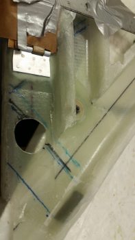
Since I used fast hardener in my epoxy, here’s a shot a few hours later when I pulled all the tape and cleaned it up. The top pic shows the valve in its normal closed state (fresh air through the ducts) while the bottom pic shows the valve open and the side edge seal at work (diverted air to heat exchanger).
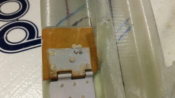
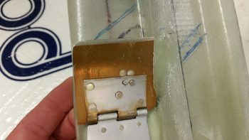
When I created the valve plate edge seal above, I also laid up a ply of glass on the inside of the bottom horizontal duct edge and peel plied it. In addition, I cut a small rectangular reinforcement piece of 0.5mm aluminum and floxed in place on the outside bottom edge of the duct and covered it with 1 ply of BID. This too got peel plied.
These layups and aluminum plate will serve to reinforce the installation of the PIC/GIB air distribution valve (valve #3) when I install it.
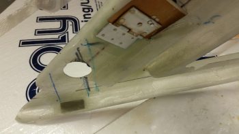
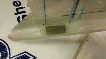
•••
5 September 2017 — Tonight I worked extensively on the pilot seat base cross duct. There was a lot of interesting stuff to come out of the initial mockups of the pilot seat base cross duct, but I think the biggest impacting one is that I learned that I had to move the planned location of my ELT to ?!? I have some ideas, but I need to dial it in… soon.
I also assessed the duct situation and drew a bunch of hash marks all over the inside of the pilot seat area. I was planning on building the PIC/GIB distro valve (valve #3) for the heating duct, but it got too late and I couldn’t cut the material due to the noise it would make.
•••
6 September 2017 — Today I started off by cutting a piece of 3/8″ foam for the initial approximately 3″ that makes up the start of the wedge shape that is the pilot’s seat thigh support. Basically what I’m doing is make the aft few inches of the pilot’s seat thigh support a triangular built-in air duct. Obviously the aft side of the 2 interior thigh support ribs will now have their tapered aft ends cut “square” so they mate up with the wedge-shaped duct that I’m making below. This is all to get the warm air over through the duct system to my right foot. Gotta keep those tootsies warm people!
After I cut the top 3/8″ piece and shaped it, I then cut the front upright –or front wall- of this wedge-shaped duct. This smaller pieces is 1/4″ foam. Since I had a scrap piece of BID that would cover half of the internal side of this wedge duct assembly, I simply cut the other half off the roll and went with 2 pieces (1 ply) of BID. As per my norm, I prepregged the BID.
The entire width of the thigh support is 17″, the same as a stock plans-built Long-EZ. A long time ago, when I widened the fuselage 1.4″ at the pilot seat bulkhead, I was more concerned about space at the shoulders. Thus, instead of widening the thigh support (the aft seat pan is a bit wider since the bulkhead is wider) I focused on widening each armrest a bit more.
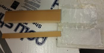
I then used fast hardener to mix up some micro to glue the 2 foam pieces together. (Unfortunately, this effort wasn’t simple and required a good hour of trial and error fitting & some resanding to get it all dialed in before joining the 2 pieces, thus the reason for the overhang of the top piece you can see in the pic below). I held the small piece in place with pins to immobilize it as the micro cured.
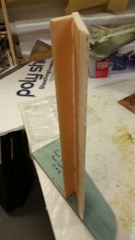
I spent a good hour prepping some other tasks while the micro cured, then while it was still tacky but structurally sound I laid up 1 ply of BID on the internal side of the wedge PIC thigh support duct. I then peel plied it at the BID ply overlap and each end.
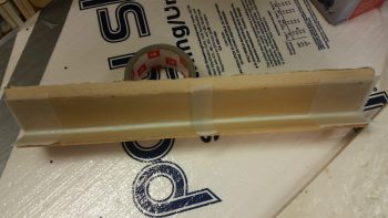
A couple hours later, after the glass was cured, I knife trimmed the glass and cut off & sanded the front overhanging piece of foam.
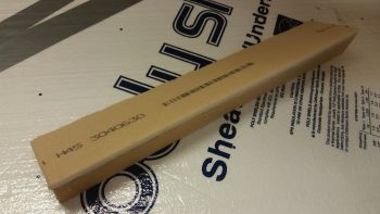
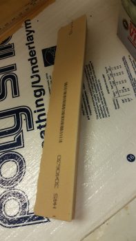
I then took my 1.25″ OD x 0.0.35″ walled 6061 aluminum tube outside and cut 4 each 1.25″ long pieces for subsequent use for connecting the 1.25″ ID SCAT tubing to the respective ducts that require it. I then spent a good 20 min cleaning up the edges on all these duct tube transition pieces.
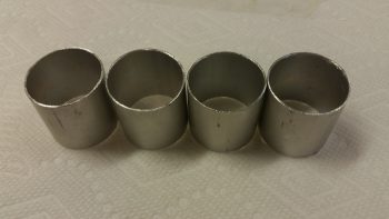
As far as ducts in the duct network that “require” a SCAT tube interface, or cross connect, I determined that with the COMM & NAV COAX antenna cables being situated right behind the air duct as it initially enters into the PIC area through the lower left pilot seat, that I should make the transition over the left seatbelt mounting bracket SCAT tubing vs. glassing a hard, permanent duct.
As you can see, when I finalized the shape of the duct coming out of the duct hole in the lower left pilot seat, I simply ran it out a few inches and capped it with one of the aluminum tube pieces I just cut.
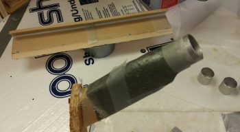
The duct tape around the hole in the pic below was for making a flange on the duct that would allow me to later flox the duct piece in place. Instead, I won’t be using that tape and will simply attach the duct piece to the lower left pilot seat with small BID tapes.
I’ll also note that I had planned on not having any of this duct piece enter the seat back duct cutout, but I then decided to leave a good lip so that it would be much stronger, and so I wouldn’t have any duct alignment issues. Yes, it will cost me a very slight penalty in airflow, but since I’m reducing my tubing diameter anyway by utilizing the 1-1/4″ ID SCAT tubing, I think it will be matched fairly close regardless.
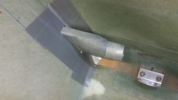
Here it is with the SCAT tubing slid in place. The area at the far right of the pic below is where this SCAT tubing piece will end and reattach –via an aluminum tube insert– back into the glass ductwork.
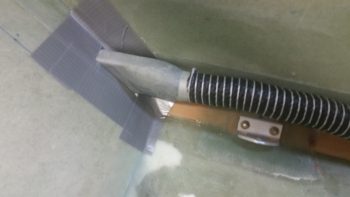
Here’s a couple shots showing the internal dimensions and airflow of the duct piece.
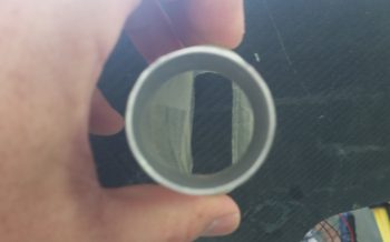
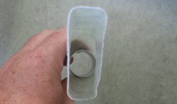
As I’ve already noted, I decided to make the duct transition over the left pilot seatbelt bracket SCAT tubing, primarily to ensure I can run my COAX antenna cables somewhat pain free, but I have a requirement to do something along that lines at the front part of the pilot seating area at the instrument panel as well.
The hole in the lower left instrument panel is a rounded square hole that my throttle handle cable connector needs to fit through. And it can just barely fit if I remove the Adel clamp (IIRC!). What is certain is that the throttle handle cable connector will NOT fit through that hole (for mounting, servicing or upgrading) if there’s a permanently mounted glass air duct running through that hole. Yes, I could glass a unique removable duct to go through there, but running a length of SCAT tubing is just the easiest & fastest option. By using a length of SCAT tubing to transition the instrument panel, then I ensure that both throttle handle cable connector remains removable as does the SCAT tubing. Moreover, they’ll fit and play nicely together.
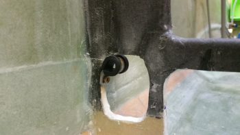
Taking into account all I stated above, then what I have in the lower middle area of my left armrest is a 2-headed snake, one at each end. I have an aluminum tube connector ⇒ glass duct ⇒ aluminum tube connector. Hmmm… if this is the setup then you may ask why not just run SCAT tube the entire length under the armrest from point A to point B? Well, because there’s a point C. In between these 2 aluminum tube pieces that connect to SCAT tubing, is the duct outlet that flows through the wedge-shaped duct at the front edge of the pilot thigh support. Again, this carries air over to the right foot vent.
Since I want to minimize the footprint of the air ducting under the left armrest, I’m trying to follow the contour of the cockpit seat pan & floor as best possible. At the corner junction of the fuselage sidewall and floor (seat pan) the contour actually changes. To allow for this I made up a front duct foam form and a separate aft side duct foam form, each with an aluminum tube connector to cross connect to SCAT tubing. (These will be joined together into one duct after they are glassed separately and I pull the foam plugs).
Since the front side of this under-armrest sidewall glass duct “plenum” was the more complex of the 2 ends, I decided to knock it out first. As per usual, I made up the form with urethane foam and then covered it with duct tape. Normally these ducts are made by taping up the foam to the sidewall and using the sidewall as part of the form, with a resulting flange created on the duct used to mount the duct later on. However, since the space is tight with the left armrest upright sitting adjacent to this duct AND the requirement to glass all around the aluminum transition tube, I went ahead and glassed all sides of with it out of the fuselage. Finally, the bottom side is mainly open so that the existing fuselage corner will still act as the duct bottom wall.
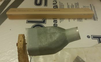
•••
7 September 2017 — I started out today pulling off the peel ply from the aft side duct piece that will be joined to the forward side to make up the middle duct assembly, or “plenum,” in the pilot seat area. After removing the foam form and cleaning it up, I then taped the 2 midpoint duct pieces into place in the fuselage.
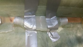
I then laid up 1 ply of BID over the exposed joint of the 2 halves. I then peel plied the layup.
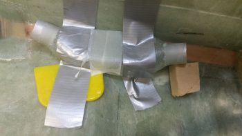
I made up a bit too much epoxy so when I finished the layup above I quickly shaped a piece of urethane foam and taped it up on the first duct piece coming forward from the pilot seat back. I then laid up 2 plies of “trash” BID over the taped foam “duct bump.” This raised protrusion will be the entry point for the #3 valve control cable, which will run through the duct and control the valve internally.
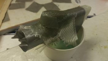
A couple of hours later I pulled the bump layup off the duct, removed the tape and pulled the foam form & tape out. I then trimmed the glass and set the control cable entry bump back onto the duct.
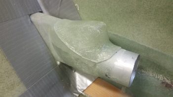
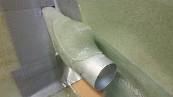
A head-on shot of the control cable entry bump set on the duct.
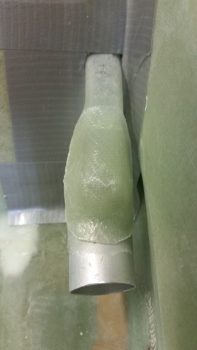
I then worked on the configuration of the pilot seat initial thigh support wedge that also serves as a cross-cabin air duct.
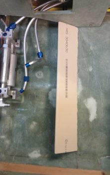
Since I needed to increase the top surface angle, with the front edge coming up, for a better intersect with the actual thigh support plate, I cut and shaped a 1/4″ thick foam bottom edge spacer. This took some trial and error to dial in due to the curves in the fuselage floor/seat pan. I also needed to finalize my glassing sequence and layup schedule, but it was getting late so I left it for later.
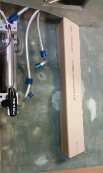
I did however layup the final BID tape joining the front & aft pieces of the PIC seat area duct “plenum” together. I then peel plied it.
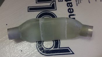
A few hours later, I pulled the peel ply off the second and final ply of BID joining the front & aft pieces of the PIC seat area duct “plenum”.
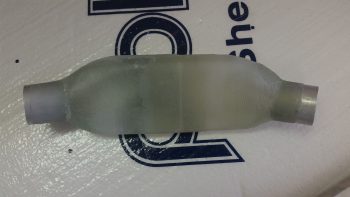
Of course then I had to mock it up to check it out. Fits like a glove and I think it will work out perfectly. I do have some more glassing to do on this component though since I need to make an exit duct on the inboard side that feeds air into the pilot seat thigh support initial wedge/duct.
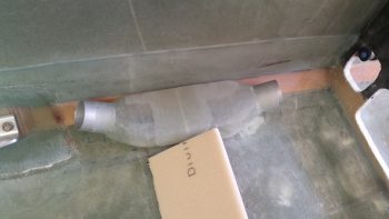
•••
8 September 2017 — I got a lot of stuff done today although from only the two pics below you may not know it.
I started off doing a hard assessment on the airflow under the pilot seat thigh support wedge that also serves as a cross-fuselage air duct for providing heat up to my right foot. I calculated the airflow a number of different times and finally decided that the internal baffle the I was considering glassing in (essentially a false duct floor) was not needed so I pressed forward.
I micro’d the 1/4″ front wedge extension piece –or spacer– onto the bottom of the front 1/4″ vertical wedge wall. I then glassed it in place with 1 ply of BID.
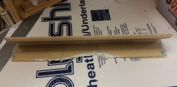
A number of hours later I razor trimmed the edges.
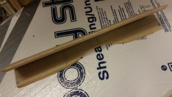
Also (sorry, no pics) I spent well over an hour designing and cutting the pieces for the PIC/GIB air distribution valve (valve #3).
•••
9 September 2017 — Today I got on to the task at hand, finalizing the components for the PIC/GIB air distribution valve, fondly known as Valve #3. Since its construction involved mechanically putting it together, with no epoxy or stuff requiring drying times, I kicked the actual construction of it down the road until I got a gap, while stuff was curing, to do it (see end of post).
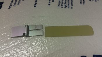
I then got into stuff that needed time to cure. As I was drifting off to sleep last night I was thinking about the wiring traversing under the pilot seat thigh support and decided to mount a couple of the smallest RivNuts I have on hand into the face of the pilot seat thigh support wedge for Adel clamp hard points. Much, much easier to do them now than later on. And these things weigh like a microgram, so any added weight would be the scant few grams of flox to hold them in place.
Along with the 2 RivNuts, I figured out the required shape of the right side end piece to cap the thigh support wedge and contain the flowing air, which, once reaching the end of the road inside the thigh support wedge duct, will make a hard left turn going forward again through SCAT tubing until reaching the glass vent assembly for my right foot.
So I got to work and micro’d & glassed the small end cap foam piece in place with a ply of BID both inside and out.
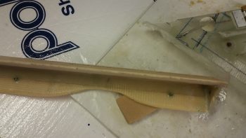
Here you can see the pilot seat thigh support wedge right end cap piece glassed in place with 1 ply of BID. You can also see the right floxed-in-place RivNut Adel clamp hardpoint and the floxed in place (only floxed at this point) Valve #3, which I drilled & riveted after I laid the wedge duct end cap piece.
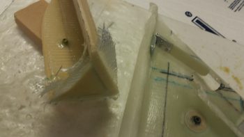
Not too much longer after I finished messing about with installing valve #3 with flox into the ductwork, the wedge duct end cap piece layup was ready for razor trimming.
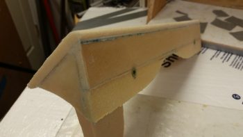
Here’s a shot of the thigh support wedge duct end cap piece on the inside.
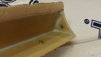
In my attempt to make things much easier in the build process I try to anticipate what next steps will have their difficulty amplified if not done sooner rather than later. Again, I really strive to get the proper sequencing down to make the build flow much smoother. Of course that’s the goal I aim at, but obviously don’t always hit my mark. However, I think I did alright in determining that with the available room afforded to me once the thigh support wedge duct was floxed/micro’d in place, drilling the 1-1/4″ diameter hole for the SCAT tubing connector was going to be tough.
That being the case, I grabbed my trusty hole saw kit and drilled this baby out.
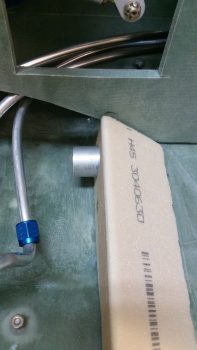
I want the connecting SCAT tubing to run as close to the fuselage floor as possible, so I angled the aluminum tubing piece downward a bit. This required that I trim it down a bit on the inside of the wedge duct if I wanted to obtain the most optimized airflow as possible.
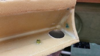
Here’s a shot from the front. I threw the Adel clamp in there to show the spacing and that the wires being secured by the Adel clamp will simply travel right underneath the duct SCAT tubing connection.
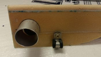
Before I mounted the pilot thigh support wedge duct I had to do 2 things: First, I needed get air flowing out of the under-armrest duct “plenum” into the cockpit-crossing wedge duct. I outlined the wedge duct’s right side end cap with tracing paper, cut it out and then transferred that to a piece of urethane foam block, and then cut out the duct shape. This was just a hair more undersized than the inside of the wedge duct to allow for general fitting and glass thickness.
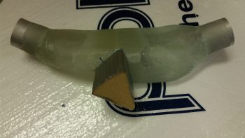
I then transferred the shape onto the intersecting side of the sidewall duct plenum and cut the same-shaped hole into the duct plenum. I worked with the foam wedge & the hole cutout to the point where the foam wedge could be mounted –unmarred– into the duct plenum side hole. I then duct taped the urethane triangular foam piece.
I then tested it out by temporarily mounting both the sidewall duct plenum and the thigh support wedge duct in place. I then realized the aft side foam wedge fit fine in the wedge duct, but there was a considerably gap at the front. So I cut another piece of foam and taped it to the face of the existing protruding foam wedge form. One slight mod later and I then taped up the foam form addition and was ready for glassing.
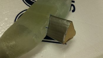
Here’s the foam form piece in place right before I glassed it with scrap BID pieces. I made the triangular form a bit longer than it needs to be to allow for trimming. This will allow it to traverse through the 3/8″ left armrest sidewall and still mate nicely into the left side wedge duct entrance.
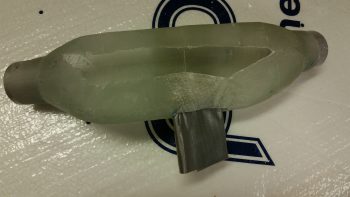
I whipped up some MGS285 epoxy with fast hardener (FYI, my 285 fast hardener doesn’t seem to cure quite as fast my 335 hardener… maybe a hardener age issue?) and glassed the new triangular “T” section of my sidewall duct plenum.
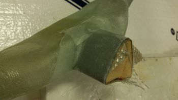
And peel plied the layup.
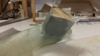
For better topic flow I’m showing the below pics now, although it came after I drilled the fuel valve bracket bolt holes.
I took the “green” state cured layup assembly above and mounted it into the fuselage in the duct plenum’s final position, which in large measure was determined by the interface of the duct plenum’s triangular air duct feed into the thigh support wedge duct, which I then set in place over the glassed (and peel plied) triangular foam form. After getting the final locations dialed in, I then weighed it all down in place to replicate the final installation positioning.
I had previously taped up both the fuselage floor and the inside of the thigh support wedge duct with duct tape so that no epoxied bits would attempt to stick permanently to anything.
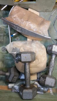
Here’s a closeup of the target intersection in my attempt to get the intersection as clean and leak free as possible, although the actual physical interface is more important at this point than possible leaks.
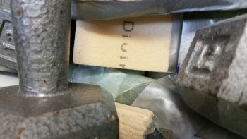
With my valve #3 having sat on the sidelines for quite a number of hours, allowing for the flox to cure, I then drilled 2 holes up through the duct reinforcement plate & extra plies of reinforcement glass, into the floxed valve attach plate.
As a point of note, valve #3’s position below would have ALL the air flowing forward to the pilot.
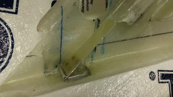
I then riveted –in not so pretty fashion– 2 round head rivets to secure valve #3 in place.
Again, below I placed valve #3 in the position showing its configuration with all the air flowing back to the GIB vents.
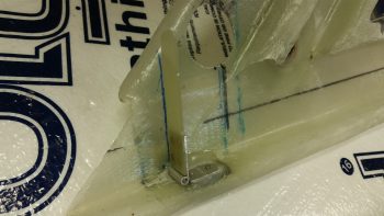
Here’s a closer shot of the rivets & flox securing valve #3, the PIC/GIB air distribution valve, in place.
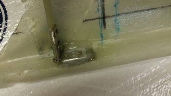
And a shot of the 2 rivets from the underside and external duct view.
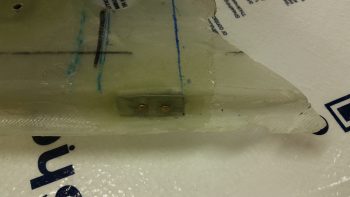
•••
10 September 2017 — Today I started out by removing the air duct plenum from the fuselage where it’s new side appendage had been shaped by the thigh support wedge duct. I pulled the peel ply, trimmed the triangle duct and cleaned up the plenum.
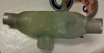
I had to trim down some glass edges inside the triangular duct, but after 15 min worth of work it was looking good.
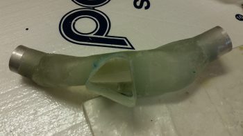
I then set it back in its place inside the fuselage. For reference the left sidewall is at the top of the pic.
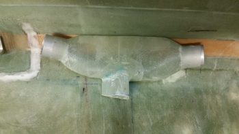
I then mocked up the thigh support wedge duct over top of the duct plenum to see how it fit.
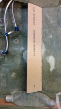
As you can see, the new air feed into the thigh support wedge duct fits nicely. My next task was to install these 2 components into the cockpit permanently, but first . . .
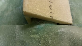
I mounted the fuel selector valve bracket mounting bolts, and once all that taken care of it was time to permanently mount the thigh support wedge duct and the duct plenum into the cockpit.
I whipped up some micro using fast hardener as usual, then micro’d/flocro’d these two pieces in place.
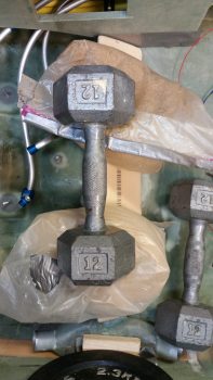
This pic may simply look like it did before, but this time they’re permanently mounted.
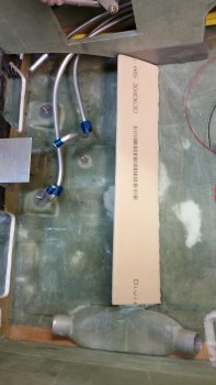
I then took about 20 minutes to sand the aft edge of the thigh support wedge duct to fair in into the existing seat pan. Once I finished sanding and vacuumed up all the mess, I glassed the thigh support wedge duct in place with 2 plies of BID, overlapping onto the cockpit floor both front & back. I then peel plied the layup.
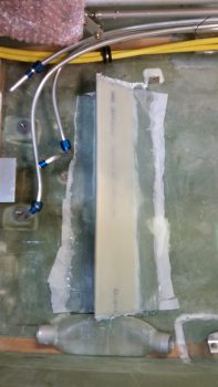
A couple hours later I razor trimmed the layup and snapped this shot of the duct plenum, mounted in place permanently.
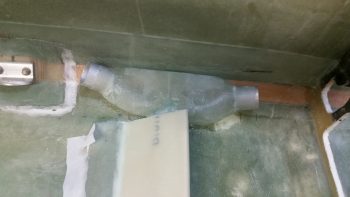
I then cut the glass out of the 1-1/4″ diameter hole for the aluminum duct vent tube, which will be used to connect SCAT tubing to the thigh support wedge duct. I then pulled the front peel ply strip and the peel ply immediately around the duct vent tube hole. I then micro’d the 1-1/4″ OD aluminum duct vent tube into place.
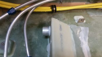
I then removed the peel ply from the rest of the pilot seat thigh support wedge duct. The pics below are simply a wider angle and closer up view of it.

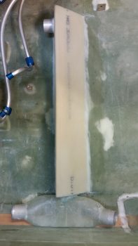
•••
11 October 2017 — Today I grabbed my 1.25″ thin walled (0.035″) 6061 tubing and cut it in order to make a “T” duct for my heating system. This “T” duct piece will sit upside down just in front of the left side instrument panel. The air will flow straight to get to my left foot, and up to get to my upper body (via a vent).
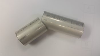
I then entered my data on the online metal calculator, printed off a template, and then taped it to the shorter piece of tubing.
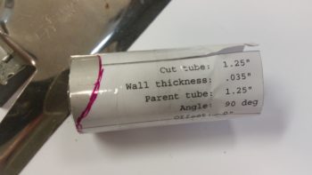
I then used my Dremel Tool to shape the end of the tube.
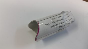
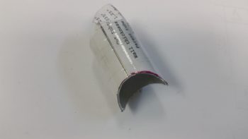
I then used the shaped tube to mark the longer tube.
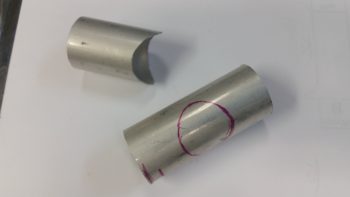
I then Dremelled a hole in the longer tube.
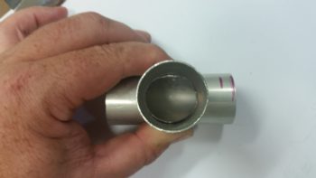
My “T” duct fitting is ready to be joined.
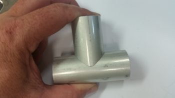
With some excess micro, I joined the two pieces of tubing together. I didn’t glass or rivet it, because these are such light pieces I think micro will do fine to hold them together. Plus, this is also not a critical flight component so I’m more concerned with weight than I am if it happens to break at some point in the future (again, which I highly doubt it will).
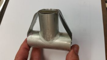
•••
4 November 2017 — Later in the evening I moved onto something a bit more quiet. Earlier in the day I decided on the mounting location for my PWM (pulse width modulator) board for controlling the oil heat pump. I drilled the 4 x 4-40 mounting holes into the front face of the lower instrument panel, left side under the armrest.
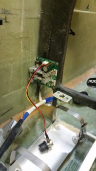
So, it was time to flox in the 4-40 nutplate assemblies to mount the Oil Heat Pump PWM board, using the 4-40 nutplates that I ordered from Stein. Of course I had to make them first . . .
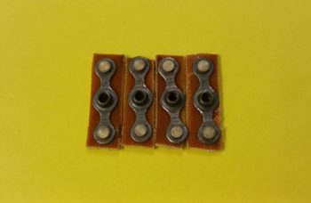
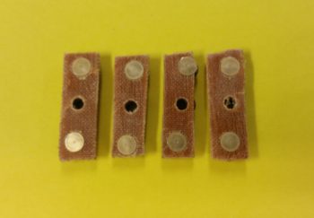
I then floxed in the 4 x 4-40 nutplate assemblies on the lower front side of the left instrument panel, with the PWM board mounted –with standoffs– on the aft side so as to ensure I got the correct screw alignment into the nutplate assemblies as they cured in place.
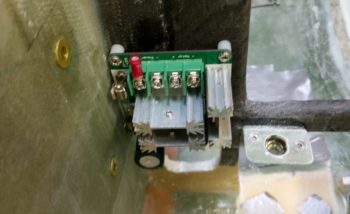
Here are the four 4-40 nutplate assemblies floxed in place on the lower left instrument panel for mounting the PWM board.
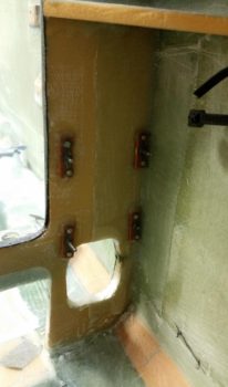
With that, I called it a night.
•••
5 November 2017 — Today my primary goal was to see if I could somewhat comfortably get the 2 seat warmer switches stacked one above the other, which I determined I could. And the secondary goal was simply to fit the inboard switches in place… which as you can see I was able to do as well.
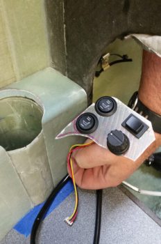
As for the heating switches, I of course stated the outboard switches are the front/PIC & aft/GIB respective seat warmer switches. The dial knob in the lower right is an OFF/speed control connected to the PWM board for control of the oil heat pump. Now, on the HIGH setting each seat warmer pulls about 4.4 amps, for a possible max total of 8.8 amps (On the LOW setting –where I plan to use them mostly– the draw is <1.5A each). The oil heat pump draws up to 7.5 amps. If I combine the totals of just my heating system output, I’m looking at over 16 amps… on a 40 amp alternator! Clearly I cannot allow this to happen, especially in flight. So the upper right button switch is a failsafe that allows me to only use one system at a time, either oil heat pump –OR– seat warmers, not both.
I then checked component installation clearance below the switch mounting plate to get an idea of what all I could fit between the switches and the mounted PWM board, since I had an idea to mount at least one of the automotive relays used to power the seat warmers. Since I need an armrest mounting bracket along the front edge of the armrest, mounted on the lower aft edge of the instrument panel (about where my first knuckle is on my index finger in the pic below), I determined there was simply not enough space for the relay… so it would have to go somewhere else [I had originally planned on mounting 2 relays for both front & aft seat warmers, but then settled for one… then none!].
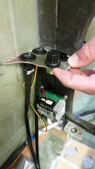
I then diverged a bit from the wonderful bouts of seemingly endless sanding foam & fiberglass (and itchiness!) to knock out the wiring harness for the heating control system. As I noted above, the pushbutton switch allows me select one system or the other: oil heat OR seat warmers. To do this required me to interject a DPDT relay into the wiring scheme.
Here are the initial relay coil power wires and flyback diode soldered in place on the heating control switches’ DPDT relay.
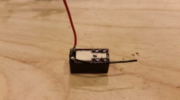
And a couple of hours later here is the wiring “harness” for the heating control system.
To help break it down a bit, the big red wire on the left is the 12V+ power wire that goes from the PWM board to the oil heat pump, via a 10 Amp inline fuse. The big blue wire on the left is the 12V+ power wire that feeds the entire heating control system (either seat warmers –OR– oil heat pump) from the main buss. The big black wire at top is the 12V- GND wire for the entire system that ties into the main GND buss (I ran out of a few colors of 16AWG wire so I didn’t run/connect a GND wire from the PWM board to the oil heat pump). The 2 inline ATC fuses that you see in the middle top area go to the seat warmer relays, one for the front seat warmer and one for the aft seat warmer. The 2 black wires on the right are the GND returns for the seat warmer relays. Finally, the 2 thick black wires at the bottom with terminated Molex connectors are the multi-wire cables to the respective seat warmer switches, front & aft.
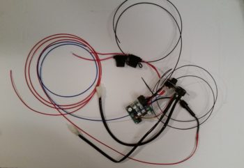
Here’s a closer look at the setup. As a point of physical mounting, I will be zip tying the DPDT switch relay to the PWM board to secure it when the system gets installed.
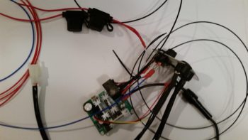
Here’s a final shot of the heating control switches, the PWM board and some of the wiring. I would like to point out that the majority of the wiring for the seat warmers will be replaced with aircraft grade Tefzel wiring.
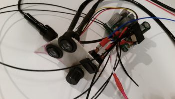
•••
6 November 2017 — I had an idea last night where to place the Pilot & GIB seat warmer relays, but this morning I determined exactly where I wanted them and pulled the trigger on mounting a clickbond to mount the 2 relays back-to-back. I used 5-min glue to initially mount the clickbond, then about 20 minutes later I used flox to transition around the edges of the clickbond and laid up 2 plies of prepregged BID over top of it. I then peel plied it.
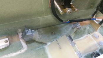
A couple of hours later I pulled the peel ply and test mounted the relays…. ah, good fit!
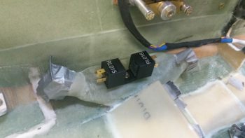
I then got to work on cutting the front left corner armrest heating switch panel out of G10. Somewhat analogous to the Dynon Intercom bracket on the right armrest, the heating switch panel will be a G10 plate that holds all the heating related switches and will become the front top surface of the left armrest. The current foam and glass of the existing armrest in that area underneath the G10 heating switch panel will get removed, all but a small ledge on the inboard side for alignment purposes.
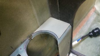
Of course it took the usual multiple iterations of fitting, trimming, sanding and refitting to get the G10 heating switch panel’s shape dialed in, but I eventually got it. I then sanded both sides of the G10 plate for its eventually getting glassed into the fuselage.
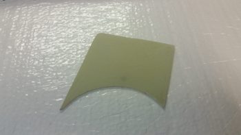
I then got to work pre-drilling the switch holes into the G10 plate. First were the 2 round 3/4″ holes that I widened slightly for the respective Pilot & GIB seat warmer switches.
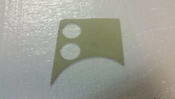
And here are the seat warmer switches installed in the G10 plate that will become the heating switch panel. (I realize that the seat symbol of the upper switch is “reclined” a bit more than the lower switch and will fix that before final switch install).
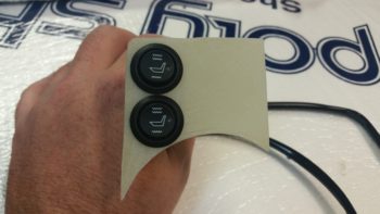
I then drilled and mounted the oil heat pump PWM control dial.
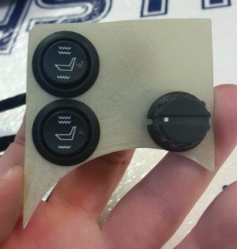
And finally the seat warmer/oil heat selector switch in the upper right hand corner.
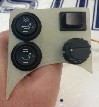
I then removed the switches and 5-min glued the G10 plate in place in the front corner area of the left armrest. I then laid up 1 ply of BID on the top surface, overlapping onto the sidewall and instrument panel about an inch. I then peel plied the layup.
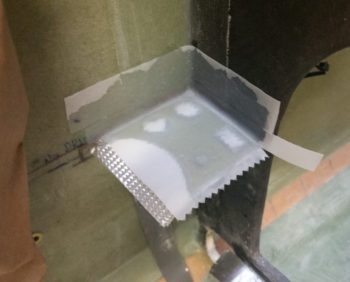
•••
7 November 2017 — I started off first thing this morning pulling the peel ply off the top heater switch panel layup and then razor cutting the glass. The plate looked good, and moreover it was really sturdy with it being glassed on 2 edges.
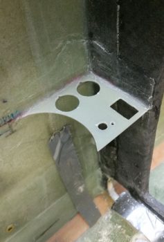
I set about immediately laying up another ply of glass on the bottom side of the heater switch panel and then peel plied it. I was going to use 2 plies of BID originally for the bottom side, but the plate felt really strong with just the top ply in place, so I figured just one more ply should do the trick in securing the switch plate.
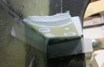
Here’s a shot from above of the heater switch panel bottom side BID ply layup.
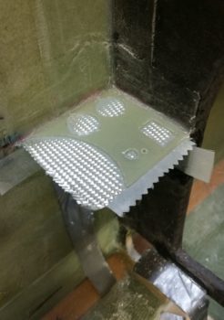
I spent a bit of time cleaning up the final ply of BID on the heater switch panel (Yes, I realize it looks just like the pic above, but in the pic below it’s finished!). Since it was getting later in the evening, after I cooked dinner I took the rest of the night off and actually turned into bed at a much more decent hour than usual…
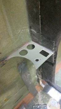
•••
14 November 2017 — I started off today installing the push-pull cable on the top of the heat exchanger (HC) for the heat restrictor butterfly valve. I quickly realized that the attachment assembly on the valve lever arm was not happy with the offset alignment I had with the Adel clamp set a bit more inboard, so I whipped up a little L-bracket to allow the Adel clamp to be mounted on the top edge of the HC vs the side. It worked like a champ.
I then set about determining where the #2 Clickbond should get mounted on the surface of the heat exchanger. I played with the alignment for a bit, and ran through a number of maintenance and troubleshooting scenarios in my head, all requiring the HC to be removed. This mandated in my mind which side the cable needed to go (on the forward side so that by simply removing a cotter pin it frees up the lever arm so that the HC can be removed).
After determining where the Adel clamp would go and the configuration of the cable run for the fresh/heater air valve, I sanded down the area around it approximately 2″ x 2″.
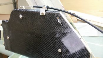
I then 5 min glued the Clickbond in place and set it under a heat lamp.
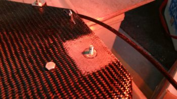
After the 5-min glue cured, I then glassed the Clickbond in place with a ply of BID covered by a ply of Carbon Fiber [Yes, I know the weave is not aligned with the original CF weave, but this was the only spare carbon fiber I had on hand and I wasn’t about to waste any by cutting it off the roll…]
Here is the mounted and glassed Clickbond…. jumping ahead a couple of hours.
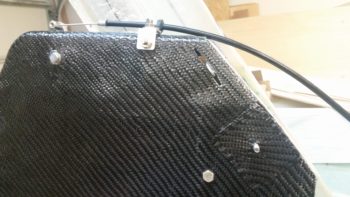
I then finalized my design for the 3-lever heat/air valve panel that will get mounted in the top middle of the left armrest, just aft of the throttle quadrant.
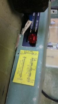
I then cut the top surface of the mounting plate out of 0.040″ thick 2024 aluminum. As you can see it extends out further than what will be seen through the hole that I’ll cut into the top of the armrest. I’ll mount 4 nutplates in the corners of this plate and mount it to the bottom of the armrest so that I can then unscrew the mounting screws and remove the plate from the armrest whenever the latter needs to be removed.
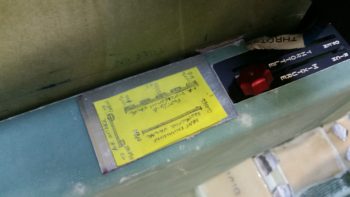
I then marked the area to be removed from the top of the left armrest for the 3-lever heat/air valve panel.
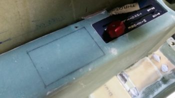
I then cut out the area using the “Fein” saw.
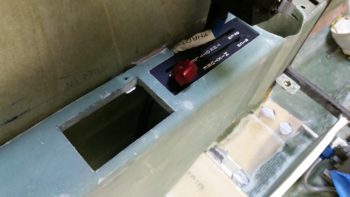
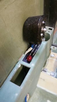
I then spent some time developing my plan for the actual cable runs coming from the heat/air valves to the 3-lever heat/air valve panel. Yes, developing mods and incorporating all of them in one place like the left armrest can definitely be a slow process at times. But I think a very necessary one in deconflicting all these components that are to be mounted. So often one decision begets another one, and even more so it may countermand a previous decision. It’s all a balancing act when cramming this much stuff (grant it, stuff I think is the right stuff to have on hand) into this bird.
For example, having just really dug deep into my cable runs, I know have to reassess my mounting location for the fire extinguisher. I may be able to simply move it to one side or the other, but right now it looks like I’ll now have to remove it from the armrest completely. I think I should be able to still mount it in the location I chose, but now the variables have greatly expanded again on where the fire extinguisher may possibly need to get mounted.
Ok, back to the actual build. I used a bit of the flox that I made up for mounting the click bond to the HC for helping to secure the 2 crimped aluminum cable ferrules that attach the valve cable to the valve plate on valve #3, the Pilot/GIB air distribution valve.
[NOTE: I made a major boo-boo in that I measured the throw of the top edge of this valve at 2.3″, which is what I used to design the lever slot for the Pilot/GIB air distribution on the 3-lever heat/air valve panel. However, a bit later when I mounted it, I determined that the cable geometry would work better if mounted it lower on the valve, closer to the fulcrum. When I tested out the valve cable runs a bit later (below) I then realized the cable only has a travel of 1″ since I relocated the cable attach point on the valve plate. Oops!]
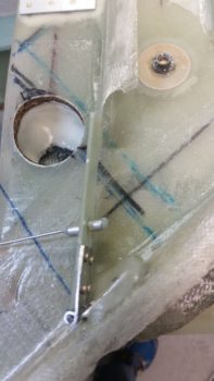
I then drilled the holes for the #1 and #2 valve cables (the fresh/heater air valve and heat restrictor valve, respectively) into the pilot seat back right next to where the duct traverses the pilot seat back as well. The #3 valve cable actually travels through the duct until it exits out.
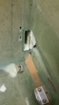
I prepped the cables and Adel clamps on the HC for valve cables #1 and #2, and installed valve #3 with the cable attached right to it. I then mounted the GIB heat/air ducts and the HC in place (temporarily). I ran the cables through their respective holes into and through the pilot seat back.
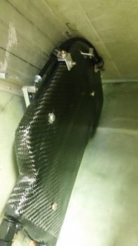
Here’s a bit closer look at the valve actuation, cables and securing Adel clamps on the HC. Plus, you can see the cable runs through the pilot seat bulkhead.
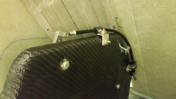
I then configured the cable for valve #3, which travels through the duct for about 6″ then, again, exits out of the duct shortly after it enters into the pilot area. To be clear, the cable conduit only barely enters into the duct via the rubber grommet, so the 6″ of cable in the duct is just the wire, not the entire cable assembly. This helps limit any negative impact on the volume of air traveling through the ducts.
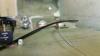
Here’s the final shot of the evening, with the 3 heat/air valve cables coming into the pilot area under the left armrest. I have to say, it was a good feeling crossing things off my 3×5 card task lists that I made up months and months ago….
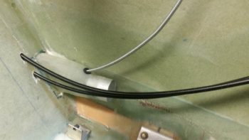
•••
2 December 2017 — I started off by reviewing what I had done before I left for the Thanksgiving break. I then trimmed the 0.040″ thick 2024 plate that makes up the 3-lever air/heater console that is positioned mid-point on the left armrest. I used the Dremel tool to notch the inboard corners of the plate to allow clearance for the left armrest’s inside corner fillet.
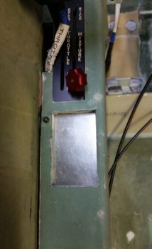
After getting the inboard side of the plate trimmed up, I then notched the plate on the outboard side to clear the armrest’s sidewall mounting bracket.
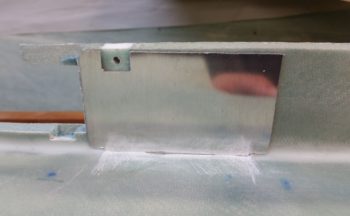
I then took the plate upstairs, along with my 3-lever plate template to measure and assess the knobs that will cap off the top of each lever. I bought the really cheap knobs below off of Ebay, but they’re a little long. I think I’ve found a source for some automotive heating knobs that might better fit the bill. I’ll assess those and possible get a few in to evaluate.
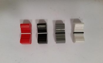
•••
11 December 2017 — Today I got to workon configuring the oil heat pump power leads after I spent a good hour of labeling and adding a couple of long wires to the oil heat PWM control and the heat seat relays.
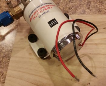
Since the wire on oil pump’s leads aren’t Tefzel, I trimmed them back fairly short and prepped them for getting solder spliced to longer 16 AWG Tefzel leads.
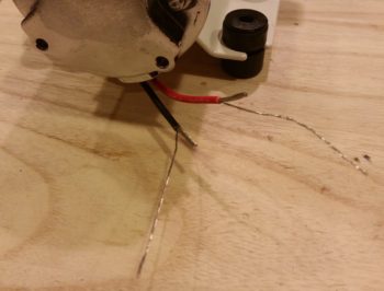
Below you can see the raw splices and the soldered splices for both of the oil heat pump’s power leads: the positive lead and ground.
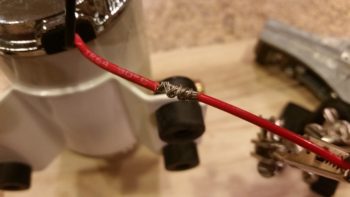
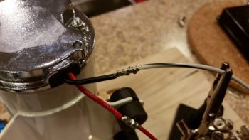
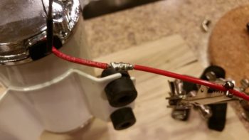
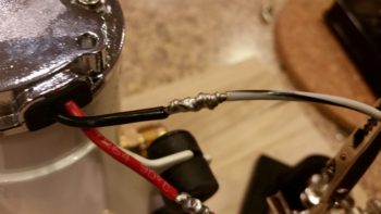
I then heat shrank the solder spliced oil heat pump power leads.
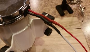
I then slightly twisted the oil heat leads together (as I did the leads coming from the PWM controller) and then labeled the leads.
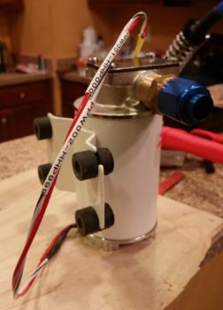
I also terminated the ends of the oil heat pump power & ground leads with knife splice connectors, just as I did the oil heat pump power wires coming from the PWM controller.
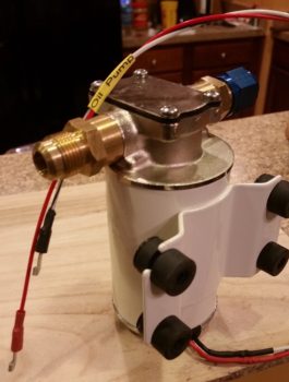
Below you can see the knife splice connectors slightly set together for the aft side oil heat pump leads to the power wires coming from PWM controller.
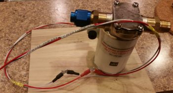
•••
5 January 2018 —Alas, in light of the amazingly cold wx on the eastern seaboard of the United States, I continued my quest to cross to-do items off my list, whether it was as banal in nature as simply ordering parts.
One such part I ordered was my instrument panel eyeball vent to allow me to focus heated air towards the upper part of me during cold flights. This Aveo eyeball vent was actually a bit tricky to decide which version to buy. At first I was leaning towards anodized silver, even took a small poll. But after getting everyones’ input and then spending a bit of time looking at both panel pics online and at my own panel, black just seemed the right way to go. I’m sure in a week I’ll want silver again… argh!
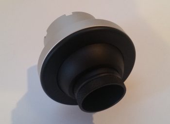
•••
24 January 2018 — Today I called GRT to solve the case of the missing EGT & CHT probes, which they are sending me the sets for my engine (an oversight on their part, but they are remedying it in an expeditious fashion).
Moreover, for this discussion, one of their EIS techs, Eric, was great in providing me a tech sheet on just how to hook up my #3 GRT OAT probe to use as an air/heat temp sensor inside my air/heating ducts. A couple key issues is that I needed to use a 4.8V excitation signal from a 5V source (luckily I now have that at the front side of the aircraft) and I needed to solder in a 10K Ohm resistor on a pigtail that went from the signal wire to ground. Once I did that, Voila! … it was up and running. With just one minor tweak of the Scale Factor setting and I was in business.
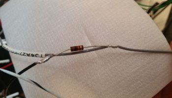
After I soldered in the 10K Ohm resistor on the ground pigtail, I then covered and secured it with heat shrink.
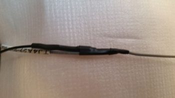
•••
29 March 2018 — Today I did a final install on the oil heat return line Adel clamp in the Hell Hole.
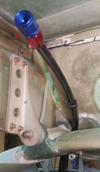
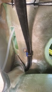
I then did the final install on the oil heat pump on the bottom centerline of the aircraft. I like this pic below because it shows the oil heat pump, finished right brake line and secured big yellow power cables.
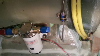
I had to spend a bit of time cleaning cured epoxy off the ends 2 of the 4 bolts hanging down from the oil heat pump, but after that I was able to bolt the pump in place EZ-PZ.
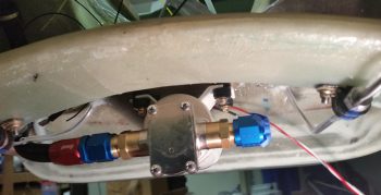
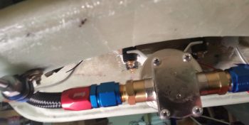
•••
25 April 2018 — Today I welded the 0.035″ walled 1/2″ 4031 steel tube inside the 1/2″ NPT x -8 AN oil heat 90° fitting. It took me a bit to rig it up so I had good access and a good welding angle, and I have to say I was going along beautifully for the first 75% of the circumference of the weld. I had to reposition the setup and I had only one little bit to go on the final weld when I slightly dipped the electrode into the puddle. Well, with so little to go I trudged forward to finish it. Mistake.
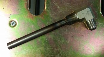
Within about 2 seconds of dipping the electrode into the puddle –with my trying to concentrate on the thicker fitting’s base metal (I tend to go high on internal corner welds)– I blew about a centimeter diameter hole in the thinner walled tubing. Since I had to buy a foot of this stuff, I ended up simply cutting a patch out for the hole from the other end of the tube. I then prepped the patch piece and the hole area, and tacked it into place.
I ran some water through the tube to see if the patch worked, but I have a couple of leaking spots that I’ll need to do some touchup spot welds after I return from NC. For now this is good, and I cut the 4130 tube at my calculated 4.4″ long (high actually).
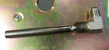
•••
3 May 2018 — Today I whipped up some micro paste to secure a length of 1.75″ x 0.035″ wall 6061 tubing over the existing 1-1/4″ tube that exits off the left side oil heat air duct that heads towards my left foot. This all will be located just forward of the lower left instrument panel and I needed this thicker diameter attach point for 1-3/4″ SCAT tubing that will feed the panel-mounted eyeball vent for heating a critical component of the aircraft: the pilot!
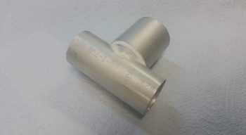
Here’s the top side of the tube addition to allow 1-3/4″ SCAT tubing to be attached to feed the panel mounted eyeball vent.
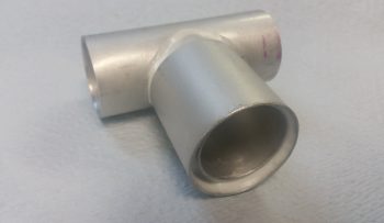
Here’s a mockup with the SCAT tubing to show what I’m talking about. The 1-3/4″ scat tubing is vertical while the 1-1/4″ scat tubing (that heads to the left foot vent) is horizontal.
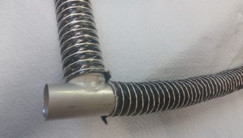
•••
8 May 2018 — Today I finished determining the configuration & spacing of the front left duct that makes up the left foot vent. At the aft end is an inverted “T” junction that allows heating air to pass upwards to the instrument panel eyeball vent. I’ll test the system out when I get the plane flying and if required I’ll add a butterfly valve to the “T” junction to control the airflow. Also, I may end up tweaking the very forward tip of the duct, which currently just opens up to make up the foot vent.
After narrowing the strip of urethane foam –that I’m using as the duct plug– from 2″ wide down to 1.5″ (still 3/4″ thick), I then taped up the lower sidewall in the avionics bay area. I then radiused the corner edges of the foam plug and taped it up to the wall over the existing protective tape. I of course had to do some foam machinations for the “T” junction to duct transition, and got it after a bit of finagling.
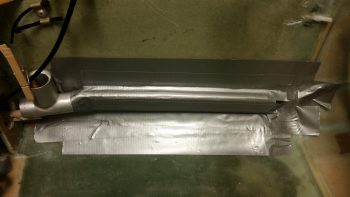
I then used a lot of small pieces out of my scrap glass pile to glass the first layer on left foot vent duct, with final bigger pieces of UNI to tie the smaller pieces together. I used fast hardener on this side and after laying up the glass I then peel plied the layup.
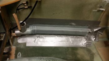
I then prepped the right foot vent duct in much the same manner as the left side. I originally had the aft duct connect tube pointed more inboard at a 45° angle, but then wanted a lower sidewall profile. The angle of the aft duct connect tube actually allows me to run scat tubing through either of the lower panel openings, providing more routing options if I should need them later on.
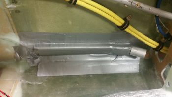
Then, just as the left side, I dug into my scrap pile and used a lot of the smaller pieces for the first ply, then covered those pieces with larger UNI pieces to make up the second and final ply on top. I used slow hardener on this layup since I knew it was going to cure overnight anyway. I then peel plied the layup,
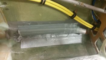
After laying up the right side foot vent duct I then pulled the left side foot vent duct off the sidewall, tape, plug and all. Then, after removing the foam plug and tape from the actual duct, I then set it back in place for the pic below. I will need to add a small amount of glass around the aluminum tubes that are embedded into the ducts on each side to finalize sealing up the ducts, but after that a trim of the glass down the sides then these foot ducts will be ready for install.
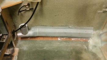
•••
9 May 2018 — Today, on the heating foot vent duct for the left side, I trimmed the glass on the edges then sanded it smooth.
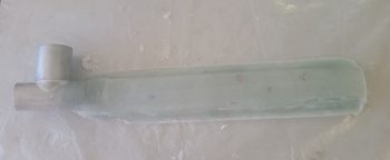
I then pulled the right side heating foot vent duct off the right fuselage sidewall, with tape and foam plug in tow. I pulled the tape off and did a little digging to get the foam plug out. Here it is with the wild and crazy glass edges in raw form.
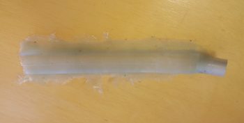
I then cleaned up the edges and sanded them. As you can see, although I tried rooting around on the underside edge with a very wet brush while laying up the glass, I still missed a spot or 2 in my epoxy application.
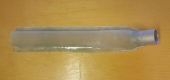
I then checked my fit by mocking it back up in place on the right side wall.
What I don’t have pics of is my repairing the dry spots on the foot vent ducts and also adding in some micro and glass on the outboard (sidewall) sides of the foot vent duct and SCAT attaching tube intersections. This was for both the left and right foot vent ducts. (Also note the white micro repair job that I failed to report on… it replaces a foam ramp that I originally glassed/micro’d in for the big yellow cables… which I have obviously since routed higher).
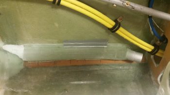
I pressed forward on determining the length of the 1-1/4″ SCAT tubing that will connect the right foot heating vent duct to the pilot thigh support integrated duct, that has the port on the right side. Once I got the required length in hand, I cut the SCAT tubing and attached it to the piece of 6061 thin-walled transition tube on the aft side of the right foot vent duct. To attach it I used my new toy: the ClampTite tool, which with 0.032″ stainless steel wire it worked a treat! In addition, in the pics below you can’t see the actual SCAT tubing on the forward side because I taped it up for painting the avionics bay.
Then using Silicone RTV and a couple well placed dabs of 5-min glue, I attached the right foot heating vent duct to the lower right fuselage sidewall between the instrument panel and F22.
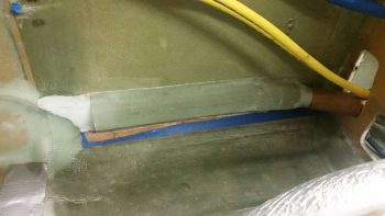
In case you’re curious, here’s the other end of the 1-1/4″ SCAT tubing for the right foot heating vent duct. The SCAT tube attach port is visible on the thigh support integral duct (see the cardboard in place over the right leg hole? …. ah, a clue as to what is coming up!)
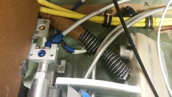
For the left side foot heat vent duct, I then measured & determined lengths on the 1-1/4″ horizontal SCAT tubing that heads straight aft to the heat duct plenum —looks like a kidney bean on the left side of the fuselage under the left pilot armrest— and the 1-1/2″ vertical SCAT tubing that feeds the panel-mounted eyeball vent. After cutting the SCAT tubing to length I attached both of them to the “T” junction ports with 0.032″ stainless steel wire using my ClampTite tool. I do have to say with the wire used to mount the SCAT tubing it doesn’t look like anything is holding the SCAT tubing in place!
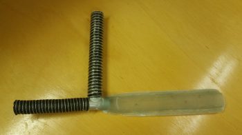
I then taped up the exposed parts of the SCAT tubing and “T” junction to protect against paint (note the cardboard and taped up items …. hmmm, looks like some painting is about to go down! . . . Check out Nose Wheel Cover insulation page and Chapter 25 pages for this paint job).
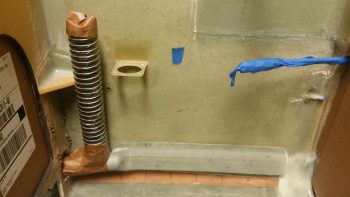
•••
13 May 2018 — Today I welded up the remaining tiny gaps in the oil heat standpipe patch that I had to weld in place when I blew out a centimeter sized hole in the tube sidewall. After an initial test to ensure there was no leaks –and there was NONE– I then ground down the weld repair to minimize it’s robustness a bit. [One thing I didn’t show here was that there was a decent blob of solid metal inside the tube as well that I drilled with a large diameter drill bit to remove].
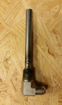
I then did one last test on the oil heat engine sump standpipe to ensure there was no leaking out or from around my welded repair patch. And there was none…. SUCCESS!
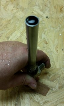
•••
25 September 2020 — After a couple of years, I finally got back around to working on a task that has been on the To-Do list for a long, long time: torquing the 1/2″ oil heat line fittings to the 1/2″-to-3/8″ reducers that run to/from the oil heat exchanger.
Since these oil line fittings sit right adjacent to the GIB fuel sump/thigh support they are quite a bit more inaccessible than I had planned on when I mounted them in that location. I was never able to fully confirm that they were appropriately torqued, so I needed a way to tighten them up to specs.
Moreover, this is a task I really needed to get accomplished pre-strake build since it would be even more of a near-impossible task to do with the strakes on.
I essentially took a Harbor Freight hollow hex “wrench” that comes in a set for plumbing, cut about 5/8″ off one end (left end, pics below), and then cut away 2 of the wrench flats to give me a 4-sided “C” piece left over.
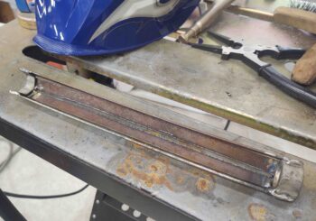
In part of my straight line cut tests for the plasma cutter, I cut a 1″ x 1/16″ strip in half lengthways, to give me 4 x 12″ x 1/2″ strips. I then MIG welded these strips to 4 of the flats of a 3/4″ bolt on one end (right end, pics above/below), and the “4-side C” I made above on the other (left) end.
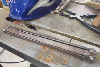
This gave me both the clearance of the hose to get in & around the oil hose fitting hex nut, while also giving me enough length to reach down along side of the thigh support to get to the oil line fitting.
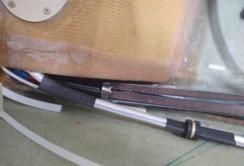
What it didn’t give me was enough torque to tighten the oil line fitting as much as it should be… it was just too springy and hard to gauge.
So I went with Option #2 –which is actually better in the long run– which this ugly wrench allowed me to do: simply remove the oil line fittings from the reducers. I’ll then mount the 1/2″ oil lines to the reducers first, then mount the reducers into the thigh support/fuel sump front face bulkhead (a bit of trimming will be required).
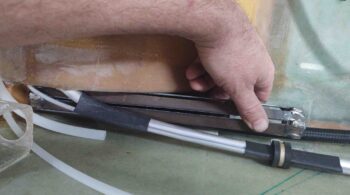
Either way, getting this taken care of pre-strake is big on my list, and I’m glad this ugly wrench was able to work in facilitating it.
•••
7 October 2020 — Today I got to work on a long overdue task, and one that really needs to be completed pre-strake build. This was the impetus for my welding up the “ugly wrench” last week to remove the 1/2″ oil heat lines coming in from the Hell Hole along the left side of the GIB thigh support/fuel sump structure and terminating each into a 1/2″-to-3/8″ reducer.
Here, from bottom (aft) up (fwd) is the black 1/2″ oil line with its red & blue fitting, connected to the blue reducer (also shown lower left), with the black fitting of the 3/8″ oil hose connected to the forward side. Note the black heat exchanger in the upper right corner where the 3/8″ lines connect to.
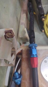
As typical, a lack of planning and a true understanding of operational impact and future maintainability bit me in the butt. At the point I created the hex-shaped pass-thrus in the GIB thigh support/fuel sump side bulkhead, I didn’t consider the left tank fuel and vent line tubing covering up these oil hoses and thus denying access to get a wrench in there to torque them to final specs… which would still have been a fairly difficult task in itself with nothing in the way.
To compound my self-inflicted difficulties, I only made the bulkhead hex pass-thrus big enough to accept the reducers’ hex nut coming in from the front of the bulkhead. The back of these holes had about a 0.2″ lip to keep the reducers from freely sliding through the bulkhead. My aim in securing them became a huge nightmare when I had to extract the 1/2″ oil line fittings in order to tighten them to spec (which they haven’t been this entire time since installed . . . years).
So I remedied that today with nearly an hour of careful (as possible) Fein saw work and manual sanding. But I eventually got the bulkhead hex passthrough lips removed so that I can preassemble the entire oil line hose assembly (as per pic above):
1/2″ hose ⇔ reducer ⇔ 3/8″ hose
all tightened to specs and then slide it through the bulkhead hex holes. I will then, as before, just use silicone to hold the reducers in place in the hex-shaped bulkhead holes.
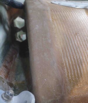
Here’s a closeup of one of the reducers.
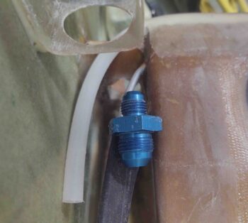
I also spent a little bit of time to knock down the thin edge that makes up the 1/2″ oil line transit hole going through the lower left GIB seat. Note the black line I marked as my target cut line.
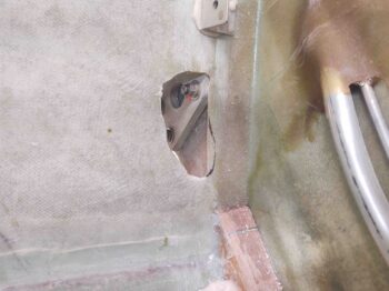
Here I’ve cut away the seat glass edge that had the potential to gnaw into the heat oil hose. I will also add a sleeves to protect the hoses further, but this was a good start to remove any potential “knife / saw” edges.
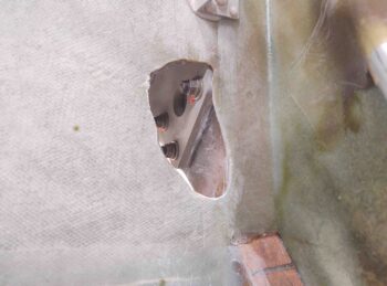
A shot of the oil lines back in place, transiting through the GIB seatback.
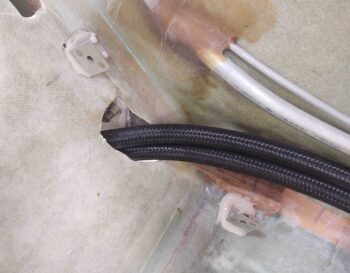
•••
12 November 2020 — I then got to work on the heat/air duct that is situated just aft of the pilot’s seat on the left side. I might not have been clear in pointing out that I am attempting to finish up the last big tasks in the GIB area prior to building the strakes. In addition, if I can get a good day or two of weather early to mid next week I would like to get the majority of the cockpit painted also prior to building the strakes.
Besides sanding a bunch of the external surfaces for upcoming paint, and sanding the edges to mount to the sidewall and seat back, I also had 4 main tasks to accomplish to get the duct work ready for “permanent” install (I’m using silicone RTV to make it somewhat removable): Trim the GIB upper duct where the transition to the eyeball vent mounts to; add a clickbond to the upper face of the duct for a throttle/mixture cables securing adel clamp; patch a small divot in the edge on the top horizontal section; and patch a rather large hole in the duct where it terminates into the channel that transits the base of the pilot seat.

Here’s the very bottom patch of the heat/air duct where it terminates into the pilot seat back:
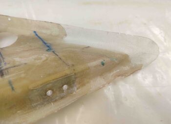
And a shot after all the glass had cured.
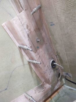
•••
13 November 2020 — Today my goal was mounting the heat/air ducts in the GIB area just behind the left-side pilot’s seat back. After my “4-task” prep yesterday, I did a final prep on the fuselage side surfaces and the contact edges of the ducts.
In case I ever need to remove this duct structure for any reason in the future, I used silicone RTV to mount it in place. The clecos do a pretty good job of holding it in position, but to ensure the duct edges were pressed as firmly as possible up against the fuselage/seat back surfaces as it cures I used Gorilla duct tape to secure the ducts in place.
This will give me a good multi-day cure on the silicone (although 24 hours is a good full cure period) to have it nice and rigid when I go to paint the cockpit. Moreover, should I need to scrape, remove or clean any silicone that is along the edges –to ensure it doesn’t thwart good paint adhesion– it will be good that it had a few days to cure and be nice and solidly fixed in place (hopefully!).
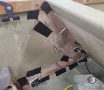
•••
17 November 2020 — I started off today checking out the heat/air duct mounting in the GIB area just aft of the pilot seat on the left side. As a reminder, I used silicone RTV to mount the ducts just in case I ever need to remove them.
After removing the clecos and duct tape, I did a quick clean up on some of the more obvious areas, and assessed the duct system attachment to the interior fuselage. Overall, I’m really pleased. There are a few minor areas that I’ll need to redo, but nothing major. In short, the ducts are definitely attached securely.
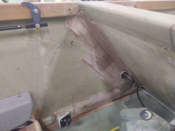
•••
20 November 2020 — On the heat/air duct I needed to reseal a couple of spots that didn’t quite pass muster. There was one strip towards the bottom, but most of it the areas of concern were all at the top.
I re-silicone RTV’d the flanges and then taped them as tight as I could get it.
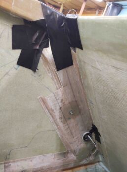
•••