
Chapter 22 – Instrument Panel Design Evolution/Mockup/Build
This page covers the multi-year design evolution of my instrument panel as well as the recent culmination of all my design efforts into a panel mockup. It also includes the wiring of panel specific electrical components.
22 December 2012 — Instrument Panel
Ok, since before I left Germany I have been working on my electrical system design. I’ve read & re-read Bob Nuckolls’ book, The AeroElectric Connection, which I think most homebuilders would agree–even if they don’t use his designs–that it’s the homebuilder’s electrical Bible.
Of course much of my electrical system design is wrapped up in the instrument panel components: how much current does each component draw? what’s my fault tolerance and mission profile? In short, what do I need, and how many of ’em do I need to feel comfortable? The design and warm fuzzy factor is of course different for each builder.
I spent a good few weeks researching all the options that I saw as viable solutions for my Primary EFIS, a back-up EFIS, an engine management system, back-up instruments, radios, etc. Basically anything that would go on my instrument panel. I built a big matrix and essentially had a run-off of just about every system out there. I also talked to a myriad of people about their take on panel designs. I called, e-mailed and pestered just about every vendor out there for information. I looked at a lot of company’s stuff, and here’s a list of the main ones I focused on:
• Dynon
• GRT
• AFS
• G3X
• TruTrak
• MGL
• TCW (back-up battery system)
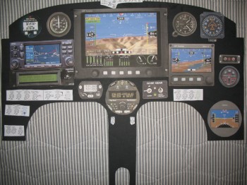
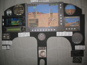
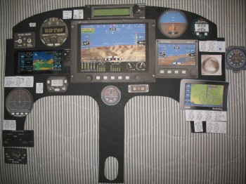
I may have looked at some others, but the list above was the main jist of my focus. In my matrix, I really focused on requirements, or in other words “needs” vs. “wants.” I also looked at current draw, weight, size, ease of use, capabilities, features, interoperability, scalability, cost, etc. It made me take a hard look at what I thought I was going to put in, and what I COULD put in. In the end, if you look at the initial pics I took in my project preparation, you’ll see it looks a whole lot different than the latest thoughts I have on the panel design. I say “thoughts,” because I still have a fair amount of time before I have to buy any panel components, and technology is always changing. So here’s the latest generic version of my panel:
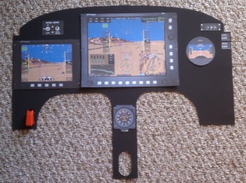
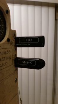
As you can see, the end result of my run off and what spit out of my matrix was Grand Rapid Technologies new 10.4 inch HXr EFIS. The “r” on the end of HX stands for remote. It allows almost every traditional panel component: radios, transponder, audio panel, etc. to be placed behind the panel and tied into & controlled by the EFIS. Another 2 capabilities that factored into my decision was the GRT’s Altitude-Heading-Reference-System (AHRS) box with it’s not requiring GPS input to function as designed… And GRT’s engine management system is rock solid and is the same one used in countless homebuilts. It’s the same engine management system box, it just gets tied into the EFIS (also remotely) where it displays data graphically.
In addition, a couple of bells and whistles admittedly helped win me over as well. I really like GRT’s HITS (Highway in the Sky) feature on their EFIS where you essentially fly through the boxes to get the plane on the ground, and their focus on IFR operations. Finally, GRT seems to play a lot nicer with other vendors out there, so they work with a lot more 3rd party market stuff (GPS, ADS-B, Radios, etc.).
Btw, the instrument panel is covered in Chapter 22 of the plans, which is the Electrical Section.
•••
10 June 2013 — After cleaning up a little bit in the garage, I then went inside the house & spent an hour or so mocking up my instrument panel & figuring out some of my avionics, etc.
•••
29 January 2014 — Over the past few months I’ve been going round and round on my Instrument Panel layout. I’ve researched a myriad of instruments & avionics, built matrices to compare various components–from clocks to autopilots–and am slowly getting a picture of WHAT components are going on the panel, maybe just not exactly WHERE the components will go on the panel. Of course, since I’ve been working on my electrical system, current draw, integration, weight and cost have all been factors in the panel plan as well.
Moreover, a lot of the panel layout will be based on ergonomics, which of course requires me actually sitting in the cockpit making airplane noises before I decide on my final configuration.
Still, I thought I would post a few pics (out of MANY) of my proposed panel options.
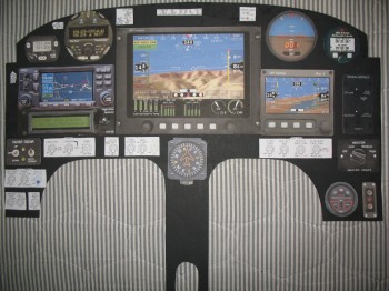
Again, my panel is currently an ever-changing storyboard. For the most part, the avionics and instruments are what I’m planning to go with presently, but as time moves on & new technologies and/or opportunities (e.g. the TruTrak ADI) present themselves the panel design can of course easily be updated.
Finally, one point of note. My panel cutout is about 0.7″ shorter in height than my real panel, so in reality I have a little bit more wiggle room to play with when stuffing various electrowhizzies onto the panel . . . if it all fits on my mock up.
•••
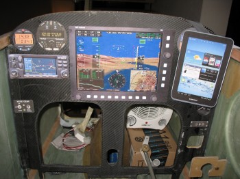
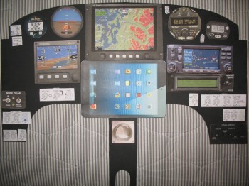
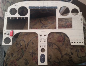
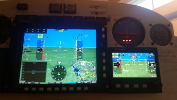
19 March 2014 — Thought I’d show a couple more of my Instrument Panel machinations. The first one below shows the real deal with the iPad Mini fired up with FlyQ EFB from AOPA, and my Android phone with the GRT app showing the Bluetooth wireless COM radio control function.
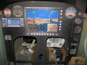
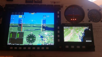
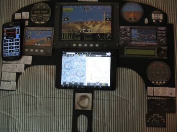 The next picture shows my throwing the big 10.4″ HXr screen PFD back onto the panel to assess how it will fit. A number of other items are on the panel to see if they fit, not necessarily in the location they’ll end up. I also swapped out the Garmin GNS430W with the Garmin GTN650 (my actual panel is about 0.7″ higher than this one at the top middle, so even thought it looks like I’ve run out room, there still some more wiggle room left up along the top curve).
•••
16 April 2014 — So I’ve been working on my electrical system. I upgraded my electrical system diagrams from a Garmin GNS430W to the GTN650. I figure by the time I buy my main Nav GPS I won’t be wanting technology that’s on Garmin’s eventual chopping block for support. Of course with the move to the GTN650, I had to add two more Circuit Breakers to the panel since it’s a mandatory requirement for them that you use CBs and not fuses. Although admittedly two CBs for 7 wires is not bad.
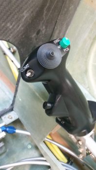
I’ve also been spending some time on my throttle and stick (HOTAS) switches. I reconfigured a number of switches between panel, throttle and stick, and in doing so was able to get rid of a couple panel switches.
Right now I’m thinking that if one has the panel real estate that the new Garmin G3X Touch is the way to go. As for me, I’m not burning that much real estate for an EFIS display. I decided that quite a while ago when I made a decision to forego the 10.4″ GRT HXr PFD for GRT’s much more manageable 8.4″ or 6.5″ PFD. Plus, as awesome as Garmin is, those bubbas tend not to play well with others’ stuff. I guess it’s a good marketing strategy, but picking up and using cool & useful third party stuff with Garmin can be problematic if ‘Big Brother G’ simply says, “No, you can’t use that crap with our suite of technological goodies! Here, use this nice GARMIN thing X instead!”
Also, now that I’m getting significantly closer to my final instrument panel and electrical system configuration, I’ve started building all my Wire Book templates. I have about 20 total templates currently completed for all the various electrical subsystems, and I’ve built 5 system diagrams from these templates so far. It should be slow steady progress over the next few months since each one that I build helps with building the remaining ones.
•••
20 April 2014 — After squawking about the new Garmin G3X Touch being too expansive for my wee panel, I decided that I should thoroughly investigate it to ensure I wasn’t missing anything important.

So this past weekend I again built a matrix to compare all my EFIS options to ensure that I’m getting the best capabilities, cost benefits, and of course weight efficiency out of my EFIS that I possibly can. Thus, I did a runoff betwixt the new Garmin G3X Touch, threw the close-sized GRT HXr 10.4 back into the mix, the GRT HX 8.4, and GRT HX 6.5.
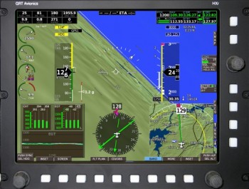
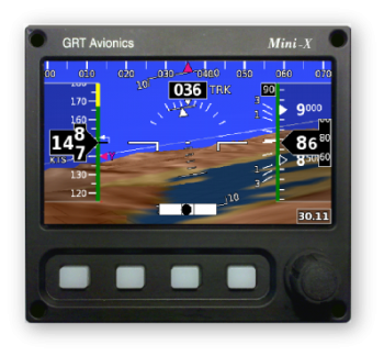
I then began to tally up all the weight, cost & current draw of all the components required to give me the capabilities I’m looking for in an EFIS system. Something to note that in all of these configurations is that the second-screen MFD and back-up PFD is the GRT Mini-X.
I was surprised as I tallied up the prices that the cost difference between the Garmin G3X Touch and the GRT HXr was less than a grand. As I trudged along in looking up component weights, and with things still looking comparable between the two systems (of course giving a slight performance edge in touchscreen simplicity to the Garmin), I hit a fairly significant snag. It appears that Garmin’s remote transponder is a robust bubba, weighing in at over 3.4 pounds with an installation depth of over 11 inches. The weight on this one transponder helped get me back to reality, realizing that I was comparing the big heavy guys, when once again I was getting plenty of capability with the smaller, very capable “little guy” EFISs that were much lighter and offered much more panel space … and thus configuration options. So once again, although tempted by cool colors and touchscreens, I dumped the big EFISs to return to smaller, lighter and more efficient.
One thing that came out of my EFIS comparison, was that I took a hard look at my allowable space BEHIND the instrument panel. I pulled out the plan’s A-pages to measure out clearances and I had a true Doh! moment. Albeit initially (Fall 2012) I had been verifying clearances behind the panel with cardboard mockups, since then I had been rearranging, adding, removing and modifying my avionics/instruments with apparent reckless abandon! The result was that I was placing components in position on the front panel with assumed clearance behind the panel.
To remedy my ways, I gathered the physical data for the displays, avionics, instruments and components all going into the panel. I clearly needed to deconflict my behind-the- panel space requirements to match what I could have on the front of the panel. I will say that I attribute this epiphany in part to Nick Ugolini since I found while reviewing his blog that he had run into this snag while redoing his instrument panel.
A significant focus in this effort is of course the area immediately behind the lower right side panel, since the elevator control rod must have free reign in its movements. I had stacked up my GNS430W/GTN650 over on the right side, having failed to verify it’s clearance with the elevator control rod, and then even added a couple of other rather deep instruments to boot. I’m glad I found it now, but I admit it was not the most optimized planning on my part.
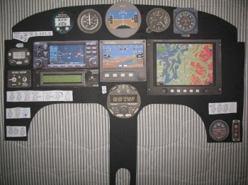
The result of all this was a trip back to the proverbial drawing board. I got out my cardboard cutouts and begin putting all the “new” puzzle pieces in place. The result is something along the lines of this:
Again, I will make note that this is still a work in progress, but at least now I am very cautious about my specific clearances behind the panel. In the back of my mind I thought I was doing this, but pulling out the actual plans verified and confirmed how little space there actually is behind our panels in these birds. And of course we all know what assumptions get us!
Build on!
•••
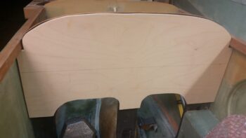
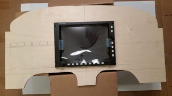
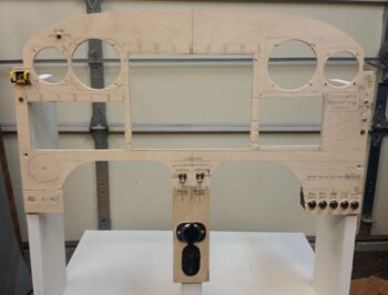
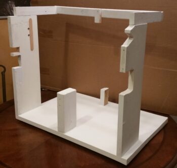
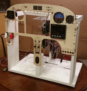
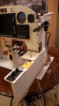
11 October 2017 — A task I did tonight was to cut out an instrument panel blank from a piece of 1/4″ plywood. I’ll use this as my initial test base for panel instrument placement and wiring.
I also spent a good 45 min working on the placement of my panel components. Here you can see where I placed the instruments on the back side of the panel. Also note that I quickly mounted the Triparagon back into place to verify how the instrument panel instruments align with it.
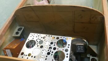
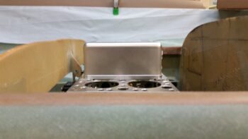
With the Triparagon mounted, I did a quick test fit on the GRT HXr EFIS GADAHRS. It looks like it will fit in its planned spot nicely.
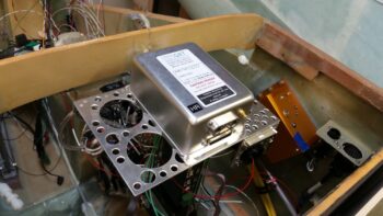
I then double checked the elevation of the GADARHS unit… also good.
•••
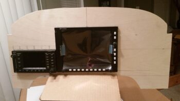
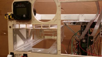
12 October 2017 — I then spent a good amount of time determining the exact location of my GRT HXr EFIS on my panel mock-up blank. I then cut the PFD mounting hole in the panel and test fit the HXr.
After a gazillion tweaks on the dimensions, trying to ensure every component gets a spot at the (panel) table, I then cut out the mounting hole for the Garmin GNS480 GPS unit that you see “installed” here.
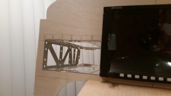
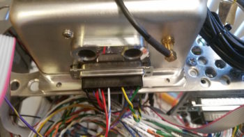
Here’s a shot of the GRT HXr EFIS and GNS480 mounting tube behind the panel.
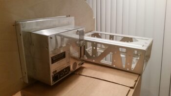
And another shot of the GNS480 mounting tube. I’ll have to play around with getting the tube mounted in this panel mock-up blank, since it is a different configuration than how it will actually get mounted in the real panel.
I then spent another couple of hours dialing in the remaining panel avionics, instruments and components.
•••
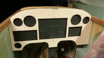
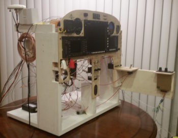
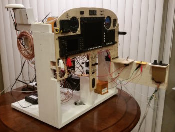
13 October 2017 — Today I got to work finalizing the instrument cutouts for the mockup instrument panel that I’m constructing. This panel will not only allow me to test instrument, avionic & component placement –and FIT!– but also put them all in their near-final position to allow me to wire them up.
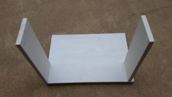
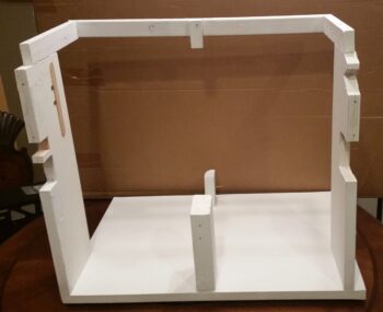
I also cut some uprights for the base of the mockup instrument panel. I’m making this panel mounting stand a bit taller than just the main instrument panel area to allow for mounting the Triparagon behind the panel, since it plays such a key role in the panel instruments’ wire cross connections. I went to dinner with my buddy Rob tonight, so before I left I spent about 15 min. painting this base with some white primer to hide all the unsightly water marks and wear on these “trash” pieces of wood that I used.
•••
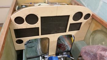
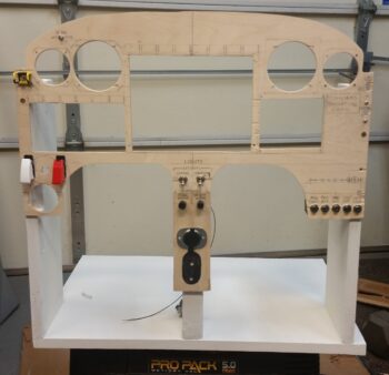
14 October 2017 — Today I cut 2 small side pieces and the center strut for the mockup instrument panel. I then glued them in place at the bottom of each panel area (L, C, R) with wood glue. An hour or so later I did a quick mock up in the fuselage to see how the mockup test panel compares to the real one. Looking pretty good!
I also did a number of things with the panel mockup, such as mount it to its base (sorry, no pics… yet). I also installed the GNS480 mounting tube and test fitted the 480… which installed nicely.
•••
15 October 2017 — I spent the evening tweaking the component locations on the mockup instrument panel.
I did have to make one major change so far: you can see in the lower left hand side where I filled the 2″ diameter heat vent hole back in by sanding down one of the 2-1/4″ instrument hole plugs that came out when I drilled the upper holes. I then glued the new 2″ round plug back into place (I wanted to get this done so it would cure overnight). The reason for doing this is that I decided the switches below the vent need to be higher for easier access, especially since the throttle handle will hinder easier access to that lower area just above the left armrest.
•••
16 October 2017 — This evening I was able to add a bit to the mockup instrument panel. If you notice, I redrilled the 2″ hole for the heating vent so that now it is located just above the left armrest intersect point. I then drilled the holes for 3 switches right above the newly relocated heating vent. I also drilled and mounted my 2 dimmers (center of center post).
•••
17 October 2017 — Today I spent over 2 hours working on my mockup/test instrument panel. I drilled out & jig sawed the 8 holes above the HXr EFIS (PFD) for the Korry status lights, and then another 6 holes above the GNS480 GPS unit for the external GPS annunciator lights (also Korry).
I then spent a good amount of time figuring out where the remaining panel components, mainly switches, will go.
•••
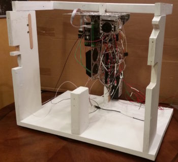
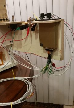
18 October 2017 — Today I added complexity to the instrument panel mockup base by creating a mounting frame for the Triparagon, since it’s such an integral part (read: epicenter) to the electrical and avionics systems.
I added a top frame assembly that mimics the F28 bulkhead, including a mounting tab for the Triparagon. On the forward bottom side I simply screwed a small block of wood in place. I then slathered on a couple quick coats of white primer to make it all match and let it cure while I was drilling and cutting out mounting holes in the panel mockup.
Quite a few hours later, I brought the dry instrument panel mockup base upstairs, since it was ready to be pressed into service.
I then mounted the Triparagon in place.
Here’s an aft/side shot of the Triparagon.
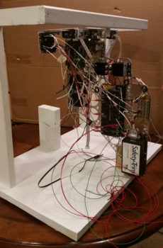
I then mounted the ELT control head (bottom component on center strut), switches and circuit breakers into the panel mockup. Right as I was getting ready to mount the panel into the base, I realized I had left out the diminutive Push-to-Test button for the top row Korry lights [I haven’t even address the actual wiring for the GNS480 external Korry light annunciators yet]. So after figuring out it’s exact location, I hauled the panel down to the shop and quickly drilled the mounting hole (with some requisite panel-thinning immediately behind it so it would fit depth-wise). I then mounted the panel onto the base front uprights.
I then mounted the compass card, GRT Mini-X EFIS, TruTrak ADI, and MGL clock.
I didn’t realize it until much later, but for some reason I inexplicably mounted the MGL clock on the front (outside) of panel vs from the back. After looking at it for a bit, I realized that I really like it this way. I will try mounting in the traditional manner and assess, but I am really liking how it looks mounted on the front side of the panel.
I then went offline for a bit panel-wise and had to dig into the Garmin GNS480 unit manual for the details on installing the backplate onto the mounting tube (bracket). My GNS480 came with the tube and an entire new mounting kit replete with a myriad of tiny screws, washers, etc. to assemble the backplate, D-Sub connectors and antenna connectors.
Once I got the backplate installed onto the mounting tube, I then mounted the tube into the panel mockup.
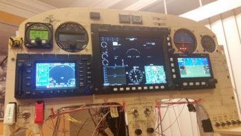
I then spent the next 2+ hours installing the remaining panel components: GNS480, GRT HXr EFIS, and Korry indicator lights.
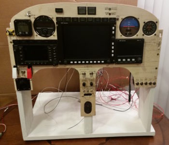
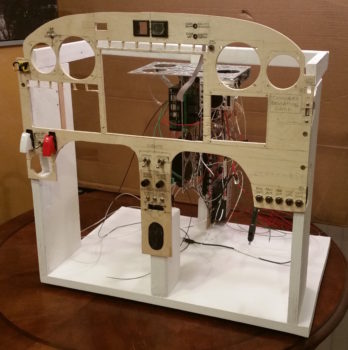
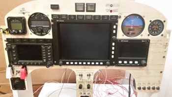
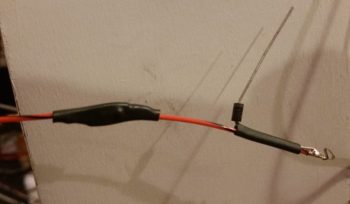
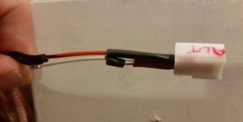
I also mounted the 2 LED warning lights that I soldered up previously. Here’s a shot of just the instrument panel . . . closer to what you would actually see in the plane.
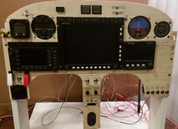
And an even closer shot of the panel components.
•••
19 October 2017 — Today was still all about the panel mockup. With a number of changes I’ve made to the wiring on the back side of the panel, I needed to check those changes to ensure they would fit my design requirements. Once I determined that I was heading in the right direction, I made the changes which required a fair amount of pulling wires out primarily out of the PQD P6 connector and then re-adding them to other connectors and/or splicing them directly into the Triparagon side wiring.
The main reason behind all this is I had a major rethink on the process of removing the panel. I had giant brain blank earlier when I didn’t take into account that my removable panel component wiring wouldn’t be routed through one giant opening in the panel, since the current composite “shadow” panel will in most respects mirror the outer 0.063″ 2024 aluminum panel overlay. This means as wires from each instrument traverses their respective holes to a common connector point, then if I tried to remove the panel after disconnecting that one connector (eg PQD P6), all the wires would get hung up at the connector as the panel was being removed.
Hard to follow? Think of an octopus on the back side of the panel reaching each of his 8 tentacles through a different hole on the panel. Then think of him grabbing ahold of 8 rods larger than each hole. You can’t pull the octopus away from the aft panel unless he releases all the rods, and you can’t pull the rods away from the front of the panel without squishing poor Mr. octopus against the back of the panel. In this scenario though, all the rods (instruments) are attached to the front panel overlay and Mr. octopus represents the panel quick disconnect (PQD) connector, while his tentacles represent the respective wiring to each instrument… hope this analogy makes sense.
Ok, so I removed the PQD P6 connector out of the equation for my MGL Clock, TruTrak ADI, and a few other panel mounted components. Thus, instead of A→B, B→C, I now simply have A→C with B (P6) cut out of the pic. Of course this change entailed lopping off wiring terminating pins & sockets and then re-terminating the wires by splicing them together. It also required a fair amount of wire relabeling as well.
My new method of panel removal for these smaller components will be to simply remove the connector at the back of each component. In the end, it should only add a few minutes to panel removal, and will also allow me a cleaner wiring harness overall since I won’t have as many convoluted wiring runs.
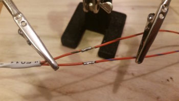
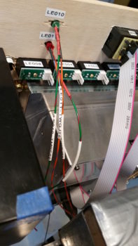
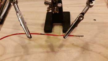
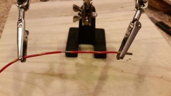
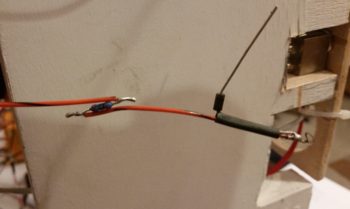
In line with all I stated above, I finished the wiring for the red & green Gear/Canopy warning system wires that I initiated yesterday. I soldered spliced the wires together for a straight shot from LED light to warning module on one side, and LED light to E-Bus power on the other. I of course labeled all the wires as well.
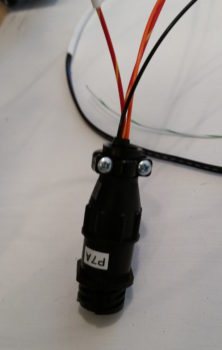
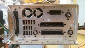
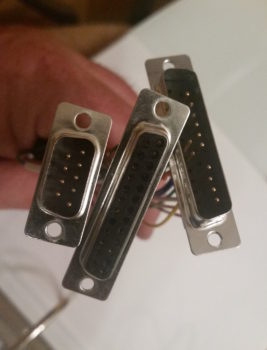
If you recall, I have 3 connectors that make up the Panel Quick Disconnect (PQD) connectors: 24-pin AMP CPC, 37-pin D-Sub, and 15-pin D-Sub. On the PQD scheme, I switched things up a while back by claiming the 15-pin D-Sub to handle the GRT Mini-X wiring only, while the 37-pin D-Sub handles the GRT HXr wiring only. However, since I didn’t have enough pins in the 37-pin D-Sub for all the HXr connections, I decided to separate out the 4 power/ground wires and connect them through a mini-Molex connector.
Thus, since the 24-pin PQD P6 connector is an AMP CPC connector, when I pulled the main, secondary, tertiary and ground wires from the P6 connector, I would need to cut off these connectors to re-terminate the wires for the new 4-pin mini-Molex connector. I then remembered that I possibly had a spare 4-pin AMP CPC connector, and after some searching around –Voila!– I did. I weighed the AMP CPC vs the mini-Molex and the difference was the AMP CPC being 0.08 oz heavier. With a much better & more robust connection, plus not wasting a couple of dollars in lopped off connectors (which I’ve already had a fair amount of!) I pressed forward with simply removing these wires out of the P6 connector and popping them into my new P7 connector. So HXr power wires on the Triparagon side are complete.
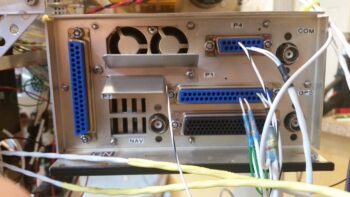
I guess my old military side came out because I then went through and labeled all the D-Sub and antenna connectors on the back panel of the GNS480 GPS unit.
And the back panel of the GRT HXr EFIS.
The moving of wires off of one connector onto another connector, or connecting straight to a wire lead all required a ton of annotations on my connector pinout diagrams.
•••
22 October 2017 — Over the last couple of days I squeezed in maybe 45 minutes each day to work on updating my electrical system diagrams, starting with my connector pinout sheets.
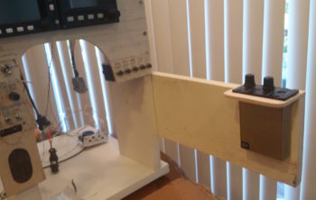
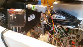
Today I started off making a bit of noise by cutting a 19.5″ long x 6″ high arm to mount to the right side of the instrument panel mockup base to allow me to mount the intercom very close relationally to where it resides in the actual aircraft. Although this intercom is small in size, the whole aft end is nothing but a D-Sub connector and there are a lot of cross connections required from the panel components.
With my requisite construction task out of the way, I then started in on what I’ve been trying to get to for the past couple of days: my electrical system diagrams. One way I keep track of all my connectors is that AMP CPC connector ID codes start with “P” (“plug”) while D-Sub and mini-Molex connectors start with “J” (“jack’). This scheme also gives me more numbers on hand for each series, since there are a fair number of distinct connectors in this airplane.
Well, besides the myriad of other updates I needed to do, including finalizing the switch out of circuits coming off the big 24-pin P6 PQD connector, I also created a new 4-pin AMP CPC plug (P7) for the GRT HXr power wires. Concurrently, I reclaimed its previous J10 tagline for the 25-pin Audio Mixer D-Sub connector.
Finally, if a connector is merely planned and has not been fully pressed into use, I may switch them around in an effort to keep the numbering scheme so that the low numbers start at the nose and get bigger as they move towards the back of the plane (i.e. J1 towards nose, J12 in hell hole, for example). Well, I stole the P7 moniker from the Trio roll servo that resides in the engine compartment and its new label is now P8. This of course required physically removing labels and adding new ones. A bit of a mundane task in doing all this, but in the end I feel wholly worth it in having a well organized, more easily maintainable, electrical system.
With the reallocation shell game complete, I then went to work updating my connector pinout diagram sheets. After those were complete, I then did a 100% review and update of all my electrical system diagrams. I added the 6 new GNS480 external annunciators to the panel diagram (#1) and tweaked all the other diagrams as well.
One major difference in my updates this time around, on a number of occasions I noted exactly how long a certain wire was that was included by the manufacturer on their wiring harness, and then approximated how much more I needed to add to complete the physical wire run. For example, on ElectroAir’s EIS Controller, that will sit in the GIB headrest, the main 20 AWG yellow wire that runs forward to the EI (“mag”) switch on the console is 6 feet long coming off the EIS Controller’s wiring harness. Not long enough to reach the front, so I annotated that on the wiring diagram. Now I know to have or reserve some 20 AWG yellow wire to extend the EIS Controller switch wire.
Beyond that, a lot of my diagrams were simply the old versions with my chicken scratch notes annotated on them, while the electronic versions were up to date. I took the time to verify the info was correct, updated other info as need be, and printed off a fresh copy of every electrical diagram. I’m sure I’ll need to do this a another few times before the plane is finished, but as of now I have a really good baseline for my entire electrical system being up to date.
•••
23 October 2017 — I started off today making a quick plan for wiring up the instrument panel. To be clear, the instrument panel is mocked up, but the wiring I’m doing now is the real deal… always subject to some upgrades (read: changes!).
The plan was to get the TruTrak ADI and MGL clock rewired since I pulled them off the P6 PQD connector and am now running all the wires from point A to point B, as I noted in yesterday’s blog. I did get them rewired, but not without the requisite issues along the way. Nonetheless, in the end they are wired & labeled correctly. So, check one!
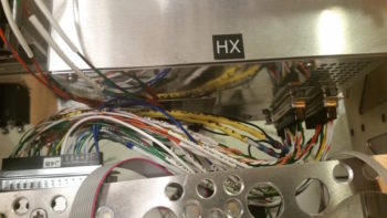
My next task was to get the wiring harness for the HXr EFIS built, which is made up of wiring leads of the 3 HXr connectors: A, B & C being consolidated into one 37-pin D-Sub connector which makes up side B of the J4 connector. Again, as I noted yesterday, since I’m a hair short on connector positions, I pressed a 4-pin AMP CPC connector into service to handle the HXr’s primary, secondary and tertiary power wires along with the single ground wire.
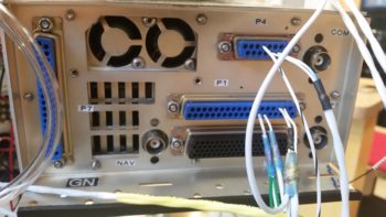
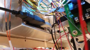
In the pic below, J4B is at the top left. Then clockwise are HXr B, HXr A, P7B and HXr C connectors. HXr A and HXr B have a smattering of different types of connections, while P7 –again- is only for power and HXr C is all ARINC 429. In addition, as you can see I didn’t just get the wires cross-connected, but all labeled as well. Finally, any wire loops you may see are the loopback grounds for the shielded wiring.
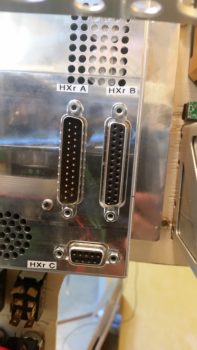
The 3 HXr EFIS connectors, in their final, populated state (l to r) HXr C, HXr A, HXr B.
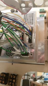
I then did a test fit of the HXr wiring harness. Below is a top-down shot. Yes, it is REALLY tight, but it all seems to fit so far.
And a shot of the 3 HXr connectors . . . installed.
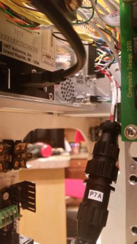
And a shot of P7 connected as well.
•••
24 October 2017 — Panel build: Day 2.
Today I started off by updating my connector pinout diagrams, reviewing the upcoming connector pinouts and then printing up 2 batches of wiring labels. I had to improvise with some larger yellow wires labels since —surprisingly— I’m out of wire label cartridges.
My goal today was to start on the J4A (front side) PQD (Panel Quick Disconnect) connector, but that quickly devolved into working on the prerequisite connector pinout on the Adaptive AHRS for the HXr EFIS. The AHRS is the recipient of a number of wires from the J4A connector, so it was natural to finish this task at this point.
I swapped out a number of wires on the AHRS wiring connector for different colors since some of GRT’s pre-installed wires didn’t match my color coding. I thought about leaving them as is, but it’s a fairly easy task to swap them and will make any future wire-hunting/tracing tasks go much easier if the wires keep the same color on each side of the connectors. I also pulled a few pre-installed wires that I didn’t need. Thus, with the AHRS wiring connector squared away, I installed it and then worked on hooking up the wires coming out of it to points yonder on the panel.
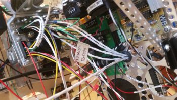
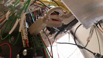
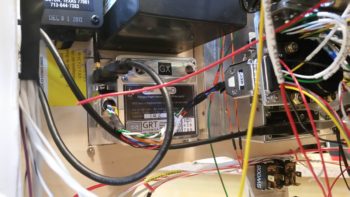
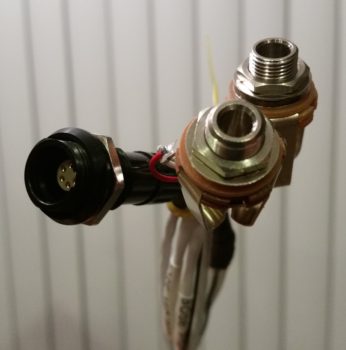
 At the aft right corner of the Triparagon… a shot of the PQD connector trio: P6 (currently unpopulated), J3 Mini-X connector (on side, vertical) and J4 HXr (top, horizontal). The relay in the foreground is Relay 9, which handles the COM1 ↔ COM2 swap. I apparently ran out of wire labels after I constructed it, so it took me a good half hour to tone it out and deconstruct what in tarnation I was up to when I made it! And with a 3PDT relay, it took a bit of head scratching. After I got it all figured out and did some quick masking tape labeling, I sent the wires off in their required directions.
[NOTE: This exercise in near-“futility” definitely reinforced to me the importance of wire labels. No matter how in-depth we get into a certain subtask, 6 months down the road all those details are lost –at least to me– and I need to “relearn” what I did! Diagrams and wire labels are the only way for me to pick up where I left off months or years later on these countless wiring components and press forward quickly].
Here’s a closer shot of the PQD bracket and connectors. The front (Triparagon) sides of the J3 (Mini-X) and J4 (HXr) connectors are for the most part complete. There’s another 8-10 wire connections that will need to be added once it’s all actually installed into the aircraft.

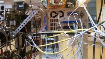
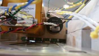
I spent a few hours constructing the 3 x ARINC 429 and 1 x RS232 shielded wire cables that all route through a centralized grommet in the Triparagon from the J4 connector to the GNS480. The pic below shows these cables from the right side of the Triparagon.
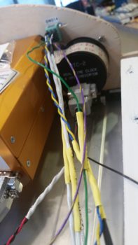
And here are the 4 ARINC 429/RS232 cables on the left side of the Triparagon, ready to be terminated into the GNS480 back plate D-Sub connectors (by the way… I installed the D-Sub connectors on the GNS480 back plate). I only terminated the RS232 cable at this point since it had standard sockets, whereas the other ARINC 429 cables require High Density pins since they get terminated into connector P5 (high density). I’m waiting until I get all the standard D-Sub pins & sockets crimped before I reset my D-Sub crimper for high density crimping.
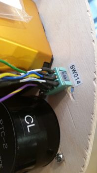
Two of the ARINC 429 and one side of the RS232 connections I highlighted above also feed the Trio Autopilot EFIS/GPS source select switch, the rather diminutive Switch #14. On the right side of the pics above & below, you can see the cross connect cables that are tied into the GNS480’s ARINC 429/RS232 cables (spliced in just before the wires enter the GNS480’s connectors) as they run up over the GNS480 to tie into Switch 14 on the panel.
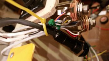
Here’s a shot of Switch 14, the Trio Autopilot EFIS/GPS source select switch, after I terminated the connections by soldering 9 wires to it: 5 connections come from the ARINC 429/RS232 cable group, 3 from the Trio AP control head, and 1 connection from the GRT HXr AHRS GPS signal.
A closeup of the 9 wires connected to the Trio Autopilot EFIS/GPS source select switch (Switch 14).
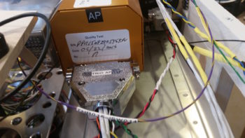
To get the wire connection lengths dialed in from the Trio autopilot to Switch 14, I had to install the massive D-Sub wiring harness on the back of the Trio autopilot.
Here’s a closer shot of the installed D-Sub connectors on the GNS480 back plate.
 In addition, I also mounted the air deflector on the GNS480 back plate.
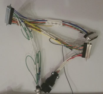
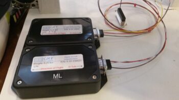
Lastly, I used some of the extra terminated wires that I pulled off the GRT wiring harnesses to make up much shorter harnesses for both the HXr and Mini-X magnetometer connectors.
•••
25 October 2017 — I started off today by cutting 2 small pieces of wood and attaching them to the existing panel mockup base with wood screws. The lower 3/4″ plywood plate, mounted vertically just below the left-side row of circuit breakers, does double duty in holding up the second horizontal plate, and at 4.5″ in depth mimics the top of the lower LHS side hole in the instrument panel bulkhead, the highest point for running wires from under the left armrest to behind the panel. In other words, all the wires going to/from the intercom to behind the panel must be run below this plate.
I mounted the second, thinner plate on top of the arm intercom-positioning jut-out at the base of the panel just forward of the row of circuit breakers. This plate mimics the left armrest console aft of the panel and forward of the control stick. Since I plan on mounting my master switch and both “mag” switches here, I went ahead and mounted my master switch in its approximate position. In this setup I’m bastardizing the master switch to serve as a power ON/OFF between battery power and main buss feed.
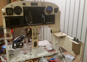
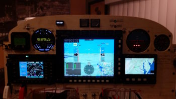
Over 12 hours later here is the panel –with about as many of the wiring cross connections completed as possible– ready to be fired up for the first time.
After I double checked all the connections, I set the battery in place and attached the leads. My battery was at 13.8 volts, which gave me a good bit of time to test out the panel.
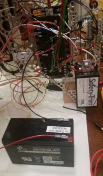
I took this shot a fair while later after I applied power to the panel. I had left the GNS480 off for quite a while since it’s a bit of a power hog as I initially worked on configuring the GRT boxes.
I had 3 main issues I need to address, one major, 2 minor:
- My HXr wouldn’t recognize the AHRS unit. I double checked all the connections, power, RS232 etc. I needed to contact GRT.
- Three of my powered GNS480 external annunciator lights (Korry) lit up even before the unit was powered on. I needed to figure this out.
- The OAT probe was inop on my nifty little MGL clock…. and had never worked. I needed to contact MGL as well.
Barring the usual snags, I was super happy with the panel.
•••
26 October 2017 — I started out today by doing a bit of electrical system administrivia until I could call GRT Avionics. I then called them and left a voicemail detailing my tale of woe regarding the AHRS not talking to the HXr EFIS. Within 15 minutes Mark from GRT called me back and within a minute I had the AHRS online. It was simply a matter of setting the baud rate to 19200 (which I couldn’t find in the documentation) and it was off to the races from there.
While I had Mark on the phone we also worked through how to set & label some of the analog ports for my specific inputs such as the GIB thigh support fuel sump low fuel alarm. He had to do some digging around but he found the info that allowed me to set all my unique analog port inputs.
Here’s another shot with some slightly different screen views than above.
Upon checking my mail I found that I had received the 4″ USB dongle I ordered to connect the HXr EFIS display to the 4-port USB hub. The USB hub connects items such as the Radenna SkyRadar ADS-B IN Receiver and by adding a little nub of a USB device also provides Bluetooth capability for the GRT EFIS system. Specifically, with a small Android tablet the GIB will be able to see essentially the same info on the PFD as I do up front.
I then installed the USB dongle . . . this is the HXr EFIS side
And here is the 4-port USB hub side. You can see there is not a lot space behind (again, technically “in front of”) the EFIS display unit.
I then prepped the Trio autopilot pitch servo for removal. I needed to remove it for a twofold purpose: 1) I needed to repair 2 of its P3 connector pins that were NOT toning out, and 2) I needed to hook it up to the panel-mounted Trio autopilot control head for testing.
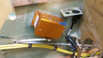
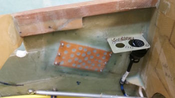
I forgot about the cool looking base floxed into place inside the right side of the nose, so I figured I would grab a currently rare shot of no pitch servo mounted on the side wall.
As I finished wiring up the Trio Pro Pilot autopilot into the instrument panel mockup, I first repaired the 2 errant connector pins on the pitch servo and then connected both servos to the Trio autopilot control head.
I also ginned up a quick little mount for a temporary autopilot disconnect switch just in front of the intercom. I picked this spot since my actual autopilot disconnect switch is on the control stick.
BTW, the connector you see in the Adel clamp attached to the outside upright of the instrument panel mockup base is the P5 connector, which attaches to the control stick cable connector.
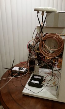
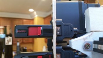
Although I temp-mounted the GNS480 GPS antenna puck last night, I thought I’d get a shot of that and the newly connected Radenna SkyRadar-DX ADS-B IN receiver sitting down low in front of the instrument panel mockup base. You can see that I zip-tied its own GPS antenna puck to the top of it, this making GPS antenna puck number 5 that is currently connected to this panel mockup! If you’re curios, here’s the list:
1—GNS480 GPS Receiver
2—HXr AHRS
3—Mini-X EFIS
4—TruTrak ADI
5—Radenna SkyRadar-DX ADS-B Receiver
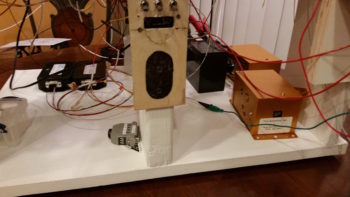
Ok, so here’s the latest shot of the mocked up instrument panel, ready for official power-on test #2 . . . which means that I am really just checking out my Trio autopilot wiring installation.
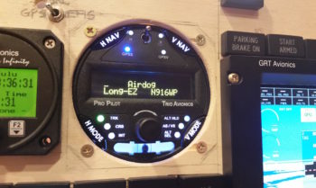
And here’s the panel with power fired up again. A quick note that not only did I resolve my AHRS connection issue, but I was able to tweak my GNS480 external annunciator lights and rewire the OAT probe on the MGL clock, so all of my 3 issues from yesterday are resolved.
My last act of the evening, as I was doing some minor configuration inputs on the Trio autopilot, was to personalize that sucker to make it MINE! [Note the blue GPSS LED light lit up as the Trio AP is talking to the GNS480 GPS receiver…]
•••
29 October 2017 — I made an honest attempt to finish installing the Dynon Intercom but was quickly reminded that I’m completely out of D-Sub connector pins and a host of other electrical supplies. After inventorying my current benchstoca levels, I put together an order on SteinAir and pulled the trigger.
I then spent well over an hour finalizing all the electrical diagram updates from the recent panel mock-up wiring.
•••
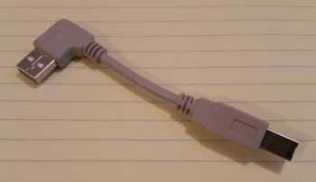
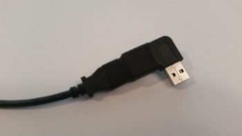
4 November 2017 — I started off today accepting delivered packages from both Amazon and SteinAir. My Amazon order contained this little gem right here:
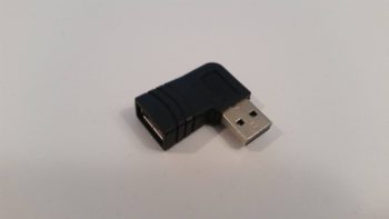
This 90° right angle USB adapter is perfect for allowing me to hook up my panel mounted USB jack to the HXr. Since the HXr’s back panel is farther forward than the panel mounted USB jack and cable, then the USB plug at the end of the cable needed to do a 180° to get to/fit into the back of the HXr. The cable’s USB plug could literally touch the USB jack on the HXr, but the geometry was such that it couldn’t go in since there just wasn’t enough length on the cable. This 90° USB adapter solves the problem by essentially turning the HXr’s rear-facing (again, technically forward in the real world) USB jack into a side-facing USB jack.
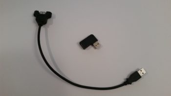
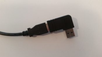
I secured the new 90° right angle USB adapter to the panel-mounted USB jack and cable with a piece of heat shrink.
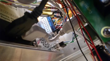
I then mounted it into the back of the HXr. I’m very happy that I now have a direct cable run and, moreover, that I don’t have to mess around with an extra foot of unneeded USB cable.
This view shows nearly the entire run of the panel-mounted USB jack and cable to the HXr, utilizing the new 90° USB adapter. Again, I’m really happy with the minimal cable length required for this connection, yet still enough slack that it’s stress free.
I mounted the USB jack onto the aft side of the panel, and then plugged in the HXr’s thumb drive.
Since I’ll be updating the EFIS’s and adding some files to their respective thumb drives, I didn’t want to get them mixed up and wanted them easily identifiable. So I took a few minutes to print off a snazzy label for each one.
Having just had separate discussions with both Dave B. and Marco on instrument panel and throttle/stick labeling, I decided since I had labeler in hand to make up a few test labels for the stick.
Not bad, but I see some modifications to these labels in the future . . . I got plans!
•••
8 November 2017 — Today I made a hard right turn in regards to my current tasks to get the cockpit component installs squared away now, so I don’t have to do them later after the install sites are buried underneath top nose foam/glass and/or behind the strakes.
I started off today with the intent of just knocking out wiring up one of micro-video cameras with an extension length of wire (a run to get from the camera which will be positioned just forward of the fuel site gage to behind the instrument panel). Why today, you may ask…. well me digress just a bit:
When I tested out the micro-video camera a few months ago I discovered that the image was definitely clear enough to incorporate for viewing not only of the respective left & right fuel site gages, but also a top camera –mounted in the pilot headrest– looking aft at the engine, prop and top cowling [perhaps a view of the GIB’s face too to ensure they’re ok]. I then decided to add a camera to view the bottom of the aircraft from the nose area looking aft, again to verify all is good down below.
With 4 onboard cameras, I needed (read: “wanted”) a way that I could bring all the cameras’ video lines together into one component to feed the HXr’s RCA-to-USB video input feed device. I talked to GRT and they stated that their USB video feed device only accepts one input. Moreover, I wanted my video feed combiner –that feeds the GRT device– to auto cycle through the cameras, showing a video feed for 3-5 seconds on each camera, before moving to the next camera. Lastly, I wanted to be able to cycle quickly to one of the 4 specific cameras to watch its video.
I posted my question on Bob Nuckolls’ AeroElectic Connection forum and besides Bob himself, got tons of interest on creating a RCA IN-to-RCA OUT video feed device that would control & cycle n number of cameras for 3-5 seconds each (user set), and would be simple to control. Bob opened up an official project file on this device and two very electronic tech savvy forum members took on the project based on my requirements. Pretty helpful (and cool) to be sure, but at this point the most pertinent part of this story is the two guys honchoing this project need camera, video feed and system data . . . from me.
Now, since I know from UPS tracking that my GRT USB video feed device will be delivered tomorrow, I decided to prep the micro video camera a bit to see if swapping out the typical bulky RCA cord for shielded 2-conduit aircraft grade wiring would work. However, as is often the case, this is the same wiring that might be required to finish off the Intercom connections . . . ok, long story to state that I felt I should finalize the Intercom wiring –a goal when I started the panel mockup wiring anyway– to figure out how much wiring that I had on hand to use for the micro camera’s video feed test.
So on to the prerequisite intercom wiring, I started off by crimping a D-Sub socket to the end of the Dynon Intercom power wire.
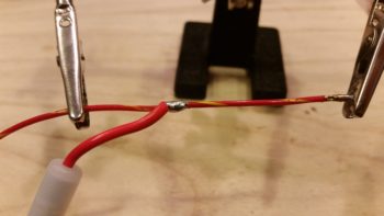
Although I could have done the next step with the wire strippers much easier beforehand, I then used a razor knife to cut away the Tefzel conductor to expose about 1/4″ of bare wire (pic #1 below).
I don’t yet have a Bose noise cancelling headset… yet, but I wanted to go ahead and get the Bose LEMO headset jack wired in with the traditional standard style headset jacks. The Bose LEMO headset jack powers the headset so that you don’t need the bulky battery pack sitting in your lap and in the way [again, not much room in a Long-EZ!). For the Bose LEMO headset power, I then spliced and soldered an inline fuse holder for a 0.25 amp fuse that is required as per the Bose connector install instructions. Of course they don’t make ATC fuses (to my knowledge) that small, so I had to go old skool with a glass fuse.
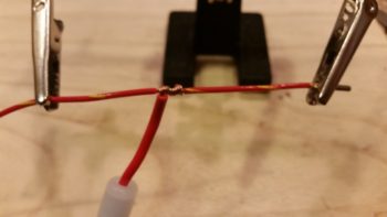
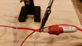
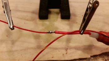
Here’s the final solder splice, connecting the Bose LEMO headset jack input power feed parasitically to the Dynon Intercom’s power wire.
I then spent a few hours, involving 4 batches of printed heat shrink wire labels (around 8 labels per batch) with the majority of those applied, knocking out the wiring connections of on the Dynon Intercom wiring harness D-Sub connector. Since most of these wires are shielded, it took a bit of time finalizing all these wiring cross-connects. In the pic below, the Intercom wiring bundled together on the table are the cables for the GIB headset jacks and the COM2 radio.
Regardless, I’m calling the Dynon Intercom wiring harness complete, with some options open for future connections (i.e. remote music jack for GIB, direct EFIS audio input, etc.).
The last push on knocking out the Intercom wiring was to connect the 2 standard headset jacks (phone & Mic/PTT) and the Bose LEMO headset connector. Besides a power & ground wire, the latter simply ties into the 2 standard headset jacks.
Here’s a bit closer shot of the headset jack wiring. My soldering won’t win any beauty contests, but it’s definitely good enough to work.
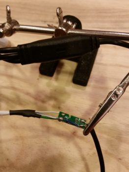
After spending quite a few hours getting the Intercom wired, including power, all the cross connects, and the headset jacks, I finally got to my initial task: wiring up the micro video camera. I had originally removed the plastic shroud –shown intact on the unmodified camera wiring above my science experiment– covering the mini circuit board that feeds the camera. While removing this plastic encasement, I nicked the circuit board and cut the thin foil circuit that connects the exterior video feed to the camera video feed. Thus, when I attached the long aircraft wiring feed to the circuit board, I also had to do a little cross connect wire addition to repair the wayward Neanderthal damage I had caused earlier.
When I tested out the extended aircraft wiring connection, the camera was much grainier than the unmodified camera. Ironically, all the trouble I went through to ensure I had enough shielded wiring on hand was probably for naught. My instinct is telling me that the shielded cable that I’m using for ground is inducing too much resistance and that I need to try using just regular wire for the ground lead. Still, I’ll continue to play with it some more to see if I can get the cameras to work using aircraft wiring for the longer leads.
•••
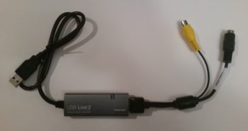
9 November 2017 — I started off today receiving the package from GRT with the USB video module that I discussed in yesterday’s blog. I looked it over a bit and noted how lightweight it is.
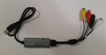
I then made it even a little lighter by summarily lopping off the left & right audio feed jacks since I know I won’t be using them in my configuration.
Of course I couldn’t resist trying it out, so I hooked it up to my 4-port USB hub, connected the camera and then fired up the panel. Within 2 pushes of a button I had the inset showing what the camera was viewing. Awesome! Especially since there was no software configuring or loading required.
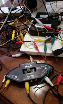
Within the next few days I should good a manual video channel switcher normally used by gamers that I got for a few bucks off of Ebay. I’ll use that for some testing and report the data back to the guys developing the video auto-switching module on the AeroElectric Connection forum.
A sideline benefit to firing up the panel and checking out the new video capability was that I also got to power up the Dynon Intercom for the first time. Now, I didn’t do anything with it to test it out, but I didn’t see any sparks, flames or smoke, so I’m going to call it good for now!
•••
12 November 2017 — Today I was able to configure both USB thumb drives for my respective HXr and Mini-X EFISs. I then upgraded the software on my Mini, which is something that I haven’t done since I bought it in 2014. I also backed up the configuration of each box to its respective thumb drive in case I need to reload my specific configuration of either EFIS for whatever reason.
I then spent well over 2 hours updating my electrical diagrams and printing out the freshly updated ones. I did a fairly significant overhaul on my heating systems diagram before I printed that one out as well.
•••
30 October 2017 — I started out today actually redoing yet another round of updates on some wiring diagrams, since I had switched around some remote functions on the GNS480 handled by the 5-way castle switch. I wanted to get the diagrams updated ASAP to reflect the changes before heading into the shop.
•••
16 November 2017 — If you recall I purchased a small USB module from GRT that allows to me port video into the EFIS from a RCA-jacked micro video camera. The inset in the lower left corner of the EFIS shows you my previously reported successful test with this added feature. Not bad.
Again, I went on the AeroElectric Connection forum to see about creating an auto-switching device that would take video feeds from multiple cameras and output them via a RCA jack to the USB EFIS video input module. Moreover, this new device needed to cycle through the cameras automatically, every 3-5 seconds (or whatever timeframe the user chooses). Finally, it also allows for the user to toggle straightway to the camera wanting to be viewed without having to wait for the cameras to cycle through.
Well, Eric Page on the AEC forum has been gracious enough to take on this project, and along with Alec Meyers, has been working to build this video auto-switching device. He did, however, need some data off an EFIS with the video capability (e.g. mine) and to do so it required I purchase a cheap video switching unit off Ebay.
In short, Eric & Alec needed to know if the EFIS would lose synch with the video feed if it were switched from one video input to another. I’m happy to report that other than about less than a half-second distortion in-between, the video switches from one to the other with no issues.
•••
9 December 2017 — After waking up to a good 3″ of snow and a shop temp barely above freezing, I set aside today to really dig into the Garmin GNS480 manuals to really get a decent baseline understanding (and relearn a ton) on how this very powerful unit works. I also rewickered the user’s manual a bit and consolidated their formatted half pages onto full standard pages for about 2/3rds of the unit’s major functions that I was interested in.
After a few hours of studying, I decided to start down the path to resolve an issue I ran into last night. To set the scene, in the 2 pics below you can see a row of annunciator lights just above the Garmin GNS480. Well, last night, right before I headed out the door for my near-weekly dinner and libations with a buddy of mine, as I was getting ready to power down the GPS unit and then the rest of the panel, I noticed that the “GPS” annunciator was inop.
So, the last couple times I’ve turned on my GNS480 I could smell a strong electrical “ozone” type smell, yet nothing was “burning.” Still it was a distinct electrical smell. Quite often I’ll leave the battery charger hooked up to the battery when I’m messing with the EFISs, but lately I was making sure to pull the charge leads off when I fired up the GNS480 …. just in case it wasn’t liking that power connection.
As I mentioned above, last night as I was flipping through different functions to light up the annunciator lights, “SUSP” was a really bright white, “LOC” half the brightness (white) as SUSP, and my green “GPS” annunciator was not lighting up at all when I went into GPS mode. I powered it all down, doing yet another sniff test (I had double checked ALL the power connections before firing up the panel… saw zero issues). I then quickly pulled out the green GPS Korry light. The top corner resistor (opposite the power leads) was fried, visibly burnt up and discolored as you can see below.
I called Stein from Stein Air and asked him if he had installed annunciator lights on the 480 (he had, but it had been well over 10 years ago and he didn’t remember anything about it). I then ran my plan by him to add some resistors to the light circuits… which ironically I was already going to do to dial down the brightness of the LED annunciators. He thought that was the best route and said that’s what he’d do. So, some R&D coming up on stuff I thought I had finalized.
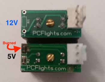
Then, late in the evening, after doing a fair bit of research on LED circuits, etc. I then went to test out a circuit that I found in a discussion that Bob Nuckolls posted on his Aeroelectric Connection forum. It was then that I noticed that the reason why the annunciator light burned out was that it was 5V model versus the 12V version that I had ordered.
To be clear, as you can see in the pic above, both the 5V and 12V PCB boards are marked as 5V. With the vast amount of time spanning between the first order and second batch of lights, I just never noted the difference and assumed the latest order was 12V (plus, I really had no way of knowing except after the fact).
In a big way I was actually glad this happened because I found out some good stuff on protecting LED lights on the AEC forum . . . especially for high powered circuits. The diode protection circuit is essentially the same as a flyback diode on a relay in that it keeps any initial voltage spikes from backtracking through the LED and frying it.
Once my “chores” were out of the way, I fired up the instrument panel to check out all my updates and see how well they worked. Plus –again– I had a number of configuration updates to input into the GNS480.
After I was done with all my checks and updates, I was going to take a few pics when I got a wild hair and decided to just film a video… so here it is:
Yes, it’s a bit lengthy (and bouncy) but hopefully it’s a good overview of the panel build.
•••
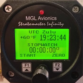
10 December 2017 — Unlike yesterday, or the past week really, today I fired up the ‘ol soldering iron and got to work. First off, I swapped out the MGL clock’s OAT probe with one of the ones I got in from GRT. I had high hopes that a new probe would solve the issue of the MGL OAT consistently reading about 5° lower than the actual temperature, even though the MGL & GRT probes are within a couple of inches from each other (no joy, so back to MGL…).
The GRT HXr has 3 separate power inputs and it simply chooses the one it likes best power-wise and goes with it. I thus have the HXr wired to the Main power bus, the E-Bus, and the TCW IBBS. In the HXr install manual it states that when first powering on the HXr, to isolate each power connection to test out the power circuit. I’ve been remiss in specifically doing this, so I took the opportunity to physically connect the HXr’s secondary power lead to the E-Bus and disconnect the HXr’s primary electrical input by removing the 3A fuse out of the Main bus. Any power issues would then be noted upon power up [there were none].
I then pulled some LED Korry annunciator light boards out of some of the ON/OFF Indicator lights that run in the row above the main HXr EFIS.
After swapping out the LED light board for a 12V version, I then soldered a diode into the circuit on the GNS480 “GPS” annunciator light. I did close to the same on the GNS480 “NAV” annunciator light, but also added a 300 ohm resistor in line. Finally, for the “SUSP” annunciator light, I simply tested that with the 12V LED board sans the diode or resistor. While I had the connectors off, I took the time to label those wires that I hadn’t gotten to previously.
Since I already had my soldering “kit” out and ready for action, I went ahead and cut, labeled and then soldered the PTT leads coming out of the P5 connector to the pilot headset jacks, finishing off all the connections that need to be soldered to those headset jacks.
My final act on the panel was to move the HXr EFIS audio output feed from the designed (but not installed) proprietary Dynon EFIS input pins on the Dynon Intercom, and simply treat the EFIS audio out as any other audio feed as far as the intercom is concerned. The big change was that I simply ran it into the intercom via the AMX-2A Audio Mixer. I then cut and terminated a set of wires, labeled them and installed the twisted wire pair between the HXr EFIS (via the J4 connector) and the AMX-2A Audio Mixer.
Once my “chores” were out of the way, I fired up the instrument panel to check out all my updates and see how well they worked. Plus –again– I had a number of configuration updates to input into the GNS480.
•••
11 December 2017 — Today I needed to knock out some electrical stuff was simply to get the area around my instrument panel cleaned up and organized. I have dozens upon dozens of wire shrink labels that need to be attached to the wires, so that’s what I started out with. I attached 5 labels, which is much more of a pain when the wires are attached into a D-Sub connector or something analogous and must be removed to attach the label.
Although I had finalized a couple of the GNS480 annunciator light wires earlier, I decided to document the last one I did for the evening (I still have 2 left to do). I’m adding in 300 Ohm resistors to help clean up the power signal and also take a slight edge off the brightness of these annunciator lights. In addition, to ensure there is no negative power spikes to damage the LEDs, I’m installing a small diode in parallel on each annunciator light for just a bit of added protection . . . just in case.
After soldering the 300 Ohm resistor in place (in a Z configuration for added strength), I then covered it with some heat shrink to secure it. You can also see the diode lead sticking up, ready to be attached to the other GNS480 LED annunciator lead. Since these protective diodes are truly optional, I didn’t waste any money on using fresh socket tabs on the end of each wire. Instead, I just tacked the diodes in place with some solder at the base of each crimped on socket tab terminal. I then added some shrink tubing for added strength to the diode lead.
Here’s the finished product for the new configuration on the GNS480 annunciator lights. This is the fourth one I’ve finished out of 6 total. Tomorrow I plan on finishing the other 2 (….as well as use up a bunch more wire labels!)
•••
12 December 2017 — Today was one of those mundane, must-do build days. I spent literally over 3 hours getting a bunch of wire labels that I had printed out heat shrunk to wires on both the mocked up panel and the cockpit heating system wires. Part of this time was spent confirming my wiring connections in the schematics, and verifying the pinouts as a precursor to below.
I then spent well over an hour verifying and updating my connector pinout diagrams. I know, I know (believe me!) … not the fun updates to read about on a airplane building website, but as I’ve said many times before: Oh, so necessary for future knowledge, troubleshooting at upgrades.
I then spent another 45 minutes soldering in a 300 ohm resistor and diode, one each, to the last two GNS480 LED annunciator lights. Let’s mark that task complete!
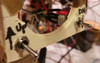
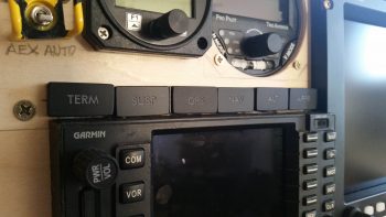
I then spent another good hour locating & installing 2 test switches OFF-(ON) that provided me with the momentary ON function I needed to emulate the 5-position castle switch that will control the remote UP-Down (and display) functions of the GNS480’s User Comm Frequency List. After digging through my spare inventory of switches, I found 2 switches that fit the bill and designated one for UP and one for DOWN.
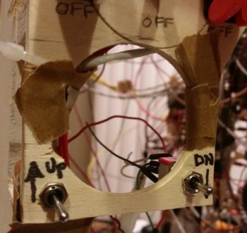
I drilled the 1/4″ holes into the bottom of the panel at each lower corner of where the pilot air/heat vent will go [again, these are simply mocked-up switches installed here to test the GNS480 User Comm Frequency List capabilities. The final actual control function will be provided by the 5-position castle switch mounted on the throttle handle, not in the locations shown]. As you can see by the tape, the amount of pressure required to drill these 2 mounting holes snapped off this bottom piece of the panel that had simply been glued into place after I moved the air vent lower. No worries, the tape held well enough for me to actuate these switches.
I then researched and verified a number of box configurations on the EFIS, GPS and autopilot. As a point of note, a lot of my latest panel configurations have been in a collaborative effort with Marco, since not only is he using 2 GRT EFISs, but he also has the GNS480 and an onboard GPSS/GPSV capable autopilot (GRT). Since Marco just converted his autopilot roll servo from the Trio EZ Pilot servo to the GRT servo, he took the opportunity to test fly it today. Thus, a long in-depth discussion ensued afterwards (a “hot-wash” if you will) on autopilot functioning and approach sequencing, etc.
It was in this discussion that Marco, who has 2 GRT Minis (-APs vs my -X) highlighted a specific issue that he has with his Minis, and that I had summarily noticed but didn’t recognize as an issue: the GRT Minis currently will NOT view an External Flight Plan that is loaded/executed on the GNS480 (at least as we both have our respective Minis programmed).
So after a fair amount of digging in the manuals, I fired up the panel in an attempt to figure out the External flight plan viewing issues on my Mini-X. Lo and behold, Marco was right. I could view the External flight plan off the GNS480 on the HXr, but not on the Mini-X. Of course, if I copied the external GNS480 flight plan into the HXr as the new Internal Flight Plan, then I could see and manipulate it from the Mini-X. This is an issue mainly as my planned role for the Mini-X is to be a fully functioning (sans vertical AP servo control) backup EFIS in case I ever lose the HXr. If I can’t see the external flight plan that is loaded in the GNS480, I would be in quite the pickle during an IFR flight in VMC, especially if a fully-coupled instrument approach was required.
Another significant issue I discovered is that through all my (latest) “initial” research in using my GRT-based glass panel, I learned that the Trio autopilot source select switch should be on “EFIS” vs “GPS” during normal flight ops. Only if I lose the EFIS would I then go “VFR-direct” from autopilot to GNS480 GPS for ARINC and GPS flight control data input. Upon learning all this, I had since switched the autopilot source select switch to “EFIS” as the default setting.
Thus, in my last video I was remiss in identifying the reason for the “NO GPS” message on the Trio autopilot’s screen as being caused by the GNS480 being in simulator mode. However, my explanation was flawed since the GRT EFIS GPS, not the GNS480, is the primary GPS source for the Trio autopilot’s GPS input when the autopilot source select switch is in the “EFIS” position. [Trust me, all this stuff gets confusing since, when the GNS480 is online, the GRT EFIS uses the GNS480’s ARINC data to provide guidance to the autopilot… it’s a very convoluted mishmash of signals and I will probably never understand it fully]. I will say that when wiring up the Autopilot source select switch, Trio warns specifically that the source signals must never be mixed: GPS = all GNS480 source signals and EFIS = all EFIS source signals.
One final note. Having been dealing a lot lately with the GNS480 annunciator lights’ open collector circuits, which are powered on the upstream side of the lights and then switched to ground inside the GNS480 if the light condition (GPS, NAV, SUSP, etc.) is active, I summarily hooked up the User Comm Frequency List function switches the same way. Oops! These go exactly the reverse in that their feed needs to start at ground, with the 12V+ coming from the GNS480. So one quick relocation of my alligator clip wire from the E-Bus to the ground bus and I had them up & working lickety-split!
•••
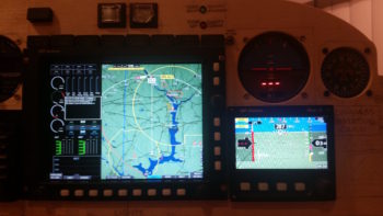
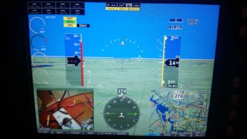
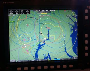
13 December 2017 — As I mentioned last night, today I started out by doing a decent amount of research in the manuals to see what I could find out regarding my panel issues. I fired up the panel to check on a few things, and set my full screen map in prep for Panel Overview video #2 that I was getting ready to shoot. Although I point it out in the video, the green highlight text in the upper left hand corner denotes that ADS-B is on, alive and well.
I also checked some parameters to get a general feel for how I’m going to link the Electroair spark advance display. I think the spark advance meter lead is most likely 12V output, so instead of conveniently hooking up it to my Engine Info box less than a foot away –all neatly stashed away in the GIB’s headrest– I’m going to have to run the wire up to the panel to connect it to the HXr for display. Not a big issue at all, just a bit easier the other route. BTW, AUX inputs to the EIS can only be 5V, thus the reason it would have to make its journey forward in the fuselage.
I then took my second video on the Instrument Panel, detailing some of the things I left out of my last video. Here it is:
As the video was rendering, and armed with just enough knowledge (so I sez to myself… ha!) I called Trio and talked to Jerry about my autopilot not receiving a GPS signal. It had before, so what changed I asked him . . . of course as the words were leaving my mouth I had an epiphany. Something had changed. With my newfound knowledge on GRT EFIS functionality, I had switched the A/P source select to “EFIS.” It then came back to me that the very first time I fired up the autopilot it immediately synched to the GNS480 (the A/P source select switch being set on “GPS . . . doh!) . . . and now set on “EFIS” it wasn’t working. Therein lied the problem: it was the connection between EFIS GPS and the Trio autopilot.

When I had talked to Chuck a few months ago, he (and the Pro Pilot manual) said that when the A/P source select switch was on “EFIS,” the autopilot was looking for NMEA GPS data. This was perfect since this is exactly the format that the GRT GPS puts out. Today though, Jerry said that Aviation GPS data should be used if I’m not getting a GPS signal (to be fair, Chuck told that if I could use Aviation GPS data, I should).
Not bragging! But in my mind it took about 30 seconds after I had my epiphany and Jerry’s input to figure out my plan of action…
My GRT HXr GPS is connected as such: First, there is a GPS antenna connected straight to the AHRS. Out of the AHRS wiring bundle is an RS232 GPS OUT wire to Bus A on the HXr. This same RS232 GPS OUT lead, immediately after it departs the wiring bundle, splits off and connects to the “EFIS” side of the A/P source select switch.
The NMEA GPS data enters the HXr on the RS232 Rx half of Serial #1. The good thing for me is that the other side of Serial #1, the RS232 Tx half of the pair, was currently empty. Since each port is programmable, I merely cut the wire from the AHRS GPS OUT to the Trio autopilot right near the “Y” junction close to AHRS wire bundle. With a new unattached wire then coming from the autopilot, I terminated the end of it with a socket and plugged it into the HXr Bus A RS232 Tx Serial #1 port. When I fired up the panel I recoded the previously empty port to handle GPS Aviation data (vs. NMEA data). The Trio Autopilot immediately came online and the display lit up like a Christmas tree!
(Note the A/P source select switch in the pic below)
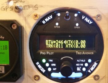
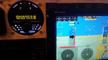
Online/connected Trio autopilot receiving GPS signals from the HXr EFIS GPS. (Note the traffic alert in the lower left corner of the EFIS).
With some physical wiring changes that just occurred, I spent a good half hour updating the associated electrical wiring diagrams.
Later in the evening I got a response back from Jeff at GRT on my forum questions regarding the Mini-X not being able to see the External flight plan generated on the GNS480. Well, not surprisingly I was missing a few key menu-set parameters on HXr and the Mini-X, that once I cleared up I had the immediate ability to view GNS480-generated flight plans on the Mini-X!
So not a bad day today…. not only have I flushed out some major issues in the last few days, but Ive been able to find the correct information to fix them. Hoo-ah!
•••
14 December 2017 — Today started out as another research and coordination day. I am still trying to nail down some details with both GRT and Electroair, and was communicating with both companies via phone and email. I guess I should include MGL in there as well. I also got some more documentation squared away on the GNS480 for future reference.
I then had to take the afternoon and early evening off to run a bunch of errands, so I really didn’t get much else done for the evening except the Instrument Panel Overview Part 3 video below, which was quite the challenge in itself. It seemed like tonight if it had electrons running through it, and I touched it, my reverse midas touch was kicking in and making everything go all haywire.
If you watched the video above, you may have noted that I hit the “SNAP” button during it, and said that I would post the resulting screenshot to this blog…. so here it is (this screen shot gives you a much better idea of the actual EFIS display colors):
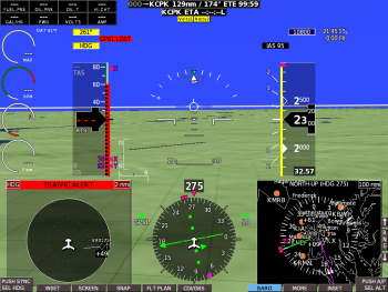
In addition, if you watched the video you’d also have noted that I resolved the issue with the Mini-X displaying the GNS480-generated External flight plan [sort of… I can display the External flight plan on the Mini-X, but not gracefully nor seamlessly. I definitely need to iron it out a tad more]. I also solved the problem of the Trio autopilot not getting GPS data from the EFIS when the A/P Source Select switch was set to “EFIS.”
•••
15 December 2017 — I started out today implementing some instructions that I got from the MGL guys to calibrate the OAT probe on my panel MGL RTC-2 Clock/OAT display. I reconnected the stock OAT probe to the D-Sub connector. I then added power to the unit and immediately went into the setup menu, and then the calibration menu. From there I was able to calibrate the OAT reading, but only to a whole integer number, and in Celsius to boot… close enough I thought.
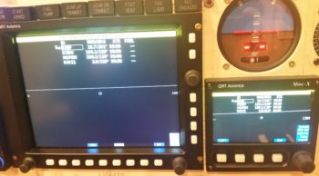
Here’s the MGL clock OAT readout after I calibrated the OAT probe readout to match the GRT OAT probe readout.
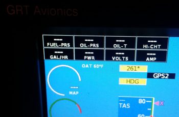
And here’s the GRT OAT probe readout below. It was good at this point, but there would certainly be an issue with a whole-integer Celsius temp reading since it would be off at some point when compared to a whole integer Fahrenheit readout. Sure enough, as soon as the OAT display on the GRT increased a bit, the OAT on the MGL was off a degree again. Since I knew the MGL OAT was now 1° max off in temp, I decided to make the fix a simple one: I simply changed the readout on the MGL from Fahrenheit to Celsius, leaving the one on the GRT Fahrenheit. There . . . problem solved! Since I can’t do the C° to F° (vice versa) conversion in my head, and I know the OAT is within 1° between the units, then one displaying C° while the other displays F° works out just fine.
Moving on from the great OAT incident of 2017….
If you watched my latest video you’ll note that I had some issues bringing up the External flight plan on the GRT Mini-X EFIS. After messing about with it a bit I determined what the deal is.
First, a reminder of my configuration: my GNS480 connects directly to the HXr via 3 ARINC connections and an RS232 connection. Conversely, the GNS480 has no direct connections with the Mini-X. Thus, the only way my Mini-X gets any of the GNS480 data is via its DU (display unit) cross link connection with the HXr. Since it’s not directly connected to the GNS480, the same holds true with displaying the External flight plan.
The bottom line is this: to view the GNS480’s active flight plan as the external flight plan on the Mini-X, both the Mini-X and the HXr must be set on GPS1(GNS480) AND the HXr must have the external flight plan pulled up (at least for the initial sync-up).
With the above true, there are really only 2 things I can do to resolve this issue:
1) Since I have no more Rx serial ports open on my Mini-X, I would have to pull off the direct feed from the EIS (engine data) and replace it with the the RS232 feed from the GNS480. This would give me autonomous flight plan display options on the Mini-X. However, if I lose the HXr then I have no engine data displaying on my BACK-UP EFIS, while for flight plan I could obviously just read it straight off of the source: the GNS480.
2) I could obtain more ports by purchasing a $300 serial 4-port expander from GRT that would provide me with enough ports for hooking up both the EIS and the GNS480 RS232 link, plus have a couple extra ports on hand for expansion.
For now, at least, I’ll simply deal with the requirement to have both DUs set on GPS1 and the external flight plan brought up on the HXr before being able to display it on the Mini-X. I honestly feel that I need engine data more if the HXr goes offline than I do being able to view the external flight plan on the Mini-X (which again, I cold view straight off the GNS480).
My final task of the evening was to install the batch of 12V annunciator lights for the GNS480 that just arrived in the mail today. This should end the saga of any more of these guys burning out. You many note that on this batch they got the correct font, which is slightly larger and more modern looking than the old style Boeing font [this is the font that I originally asked for in the original order, so besides the 12V (vs 5V) lights, they fixed the legend fonts as well].
•••
30 December 2017 — Today the weather here was VERY cold, dipping down to ~10° F (-12° C). So NO shop work when it’s that cold.
On the good news side of things . . . I got an email from Eric Page, the friendly neighborhood electronics guru off the AEC forum. He has finished my one-off “Deslumpifiier” that should allow me start my engine with my GNS480 already turned on & flight-plan loaded. Eric also just sent the completed circuit board up to Alec in Canada for chip coding the onboard 4-into-1 video camera signal processing unit that will feed my GRT EFIS video inset view capability. This video signal combiner component will end up being about a 6-7 month long collaborative effort by the time I get it into my hands, so again, I’m glad to be getting the more esoteric instrument/electrical requirements through the queue before the real avionics install takes place.
In addition, Eric is close to finishing the tiny circuit board that will have the Bob Nuckolls’ recommended AD626 op amp chip mounted onto it, which will crisply increase the Electroair spark advance signal x10 to allow a very granular input into the GRT EIS box for displaying realtime Electroair electronic ignition spark advance data on my EFIS screen.
•••
5 January 2018 — In light of the amazingly cold wx on the eastern seaboard of the United States, I continued my quest to cross to-do items off my list, whether it was as banal in nature as simply ordering parts.
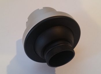
One such part I ordered was my instrument panel eyeball vent to allow me to focus heated air towards the upper part of me during cold flights. This Aveo eyeball vent was actually a bit tricky to decide which version to buy. At first I was leaning towards anodized silver, even took a small poll. But after getting everyones’ input and then spending a bit of time looking at both panel pics online and at my own panel, black just seemed the right way to go. I’m sure in a week I’ll want silver again… argh!
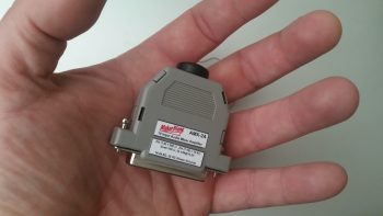
I also received my “Deslumpifier” from electronics guru Eric Page. He did a great job and his Voltage Slump Eliminator construction looks very professional. It’s not too obtrusive in size and will add a great feature to my panel by allowing me to simply enter an entire flight plan into my GNS480 GPS navigator –on battery power and thus stress free regarding time (e.g. NOT sitting there burning mucho dinero in the form of 100LL)– before I then power up the engine whilst leaving the GNS480 on. Good times!
After checking out the “Deslumpifier” I then spent well over an hour updating my engine management system and panel power electrical system diagrams, as well as creating a sheet to cleanly annotate all my current GRT EIS4000 configuration settings.
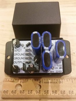
Another nice little surprise at the very beginning of 2018 was a text I received from Marco pointing out an announcement on Grand Rapid Technologies’ website. They are now offering the special features package (EIS data display, Bluetooth and ADS-B display) for free on their Mini-X and Mini-AP EFISs. Well, it ended up that I didn’t qualify for the “free” package, but I found out that I could get it at a greatly reduced price when I ordered my last GRT engine sensor: the Hall Affect Amp sensor.
Since I have Bluetooth and ADS-B on my HXr, I wasn’t concerned about those displaying on my Mini-X. However, I did really want the capability to display engine data on my Mini-X in case my HXr EFIS display died inflight, so I pulled the trigger and ordered the software.
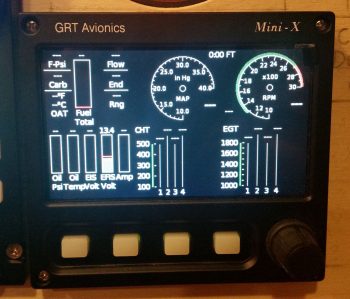
What I didn’t realize was how well laid out the Mini-X engine data display would look (IMO). A few hours after pulling the trigger on the software, I received an email from GRT and was able to update my Mini-X to display engine data. I have to say that I’m really pleased with how it looks (of course, again, these pics don’t do it any justice!).

Here’s a wider angle view with the checklist displayed in the lower left inset on the HXr. I did this to simply show that if I was messing about with a checklist, or had a full screen map or approach chart displayed, that with two button clicks I can very easily bring up the Mini-X engine data screen. So, not only is it a great backup feature to the HXr, but it clearly offers a lot of flexibility to provide flight-centric information in a variety of ways.
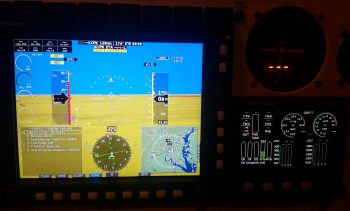
•••
6 January 2018 — Today I started out by attaching about a half-dozen preprinted labels to component wires on the instrument panel. By the end of the evening I had printed out another 2 batches of heat shrink wire labels and attached nearly all of them to their respective wires. I have to say that printing out and attaching wire labels is definitely an exercise in perseverance and patience, but in the end I know it will be way worth the effort.
I then worked on constructing some new power and ground cables for the “Deslumpifier” AKA Voltage Slump Eliminator. Since the power IN for the Deslumpifier needs to be fused, I just picked a location on the Triparagon that allowed me to simply use a robust inline fuse holder with leads as the main power cable. Right now I’m fusing it with a 7.5A ATC fuse which I think is a good starting point. To match the massive leads of the inline fuse power cable, I used a black 14AWG lead for the ground cable.
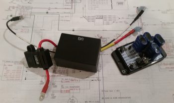
I then cut, labeled and re-terminated the existing power and ground leads to the GNS480 to allow them to be hooked up to the Deslumpifier. After I finished the GNS480 leads, and before final hookup, I tested the Deslumpifier’s output (to ensure no power surges into the GNS480) and it showed 13.84 volts… definitely good to go. I then terminated all power and ground leads into the Deslumpifier (note the grommet).
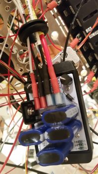
Backtracking just a bit . . . actually before I went final with hooking up the leads above, I cut an initial hole, then widened it into a slot on the end of the Deslumpifier cover where the leads connect onto the board. After stuffing all the leads into the grommet I had a good idea just how wide the grommet hole/slot needed to be, so I then finalized cutting the appropriate sized slot for wire lead access into the Deslumpifier, including the grommet of course. I then slid the grommet into the cover’s end slot and mounted the cover onto the Deslumpifier.
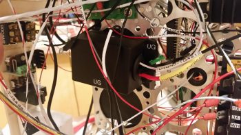
With the wiring looking good on the Deslumpifier, I then powered up the panel, including the GNS480. Below is a wide angle view of the panel showing that the Deslumpifier works fine in powering the GNS480 in battery mode. Much later on I’ll conduct Phase II testing which will be during actual engine start to see if the Deslumpifier will keep the GNS480 from rebooting.
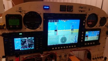
I have to say that although there was a lot of mundane work that took place today, it was quite productive.
•••
8 January 2018 — Today I focused on my 12V-to-5V power converter. What will it be used for you ask? Well, in order to use an aft-looking wide angle video camera that I’m going to mount at the top of the headrest, I need to use a 5V power signal to drive it. In addition, I want to mount and use my Bendix/King AV8OR portable back-up GPS in the lower left corner of the panel, which too uses 5V power.
So I made up, labeled and terminated the power and ground wires for the 12V-to-5V power converter and screwed them in place on the terminals.
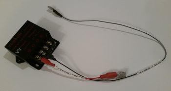
I have a power wire jack on order for the BK AV8OR GPS, and I need to acquire some 24AWG wire before proceeding with wiring up the video camera, so below is as far as I’m going to go on the 12V-to-5V power converter for now.
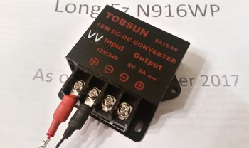
I then assessed and marked the plywood instrument panel mockup to drill a 3/8″ hole for the panel ON/OFF indicator LED lights’ dimmer.
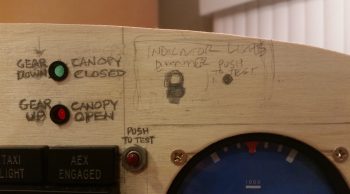
After drilling the hole and cleaning up the sawdust, I then test mounted the dimmer switch and knob…. not bad.
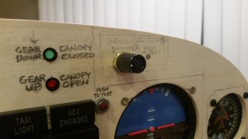
I then got to work on cutting and soldering the panel ON/OFF indicator LED light ground wires to the dimmer switch.
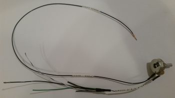
While I was in the vicinity, I also removed the panel ON/OFF indicator LED lights’ Push-to-Test switch and soldered the power leads to it as well.
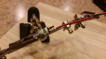
I then added heat shrink over the soldered leads for protection.
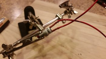
•••
10 January 2018 — Today I prepped a small “toy” that I just received in the mail: a 4.0mm OD x 1.7mm ID corded jack to power my Bendix/King AV8OR backup GPS. I determined a good length for the cord and ended up cutting off about half of it. I then cut each end of the cord’s 2 conductors and spliced on cheap ring FastON terminals since later I’ll make both a final cord length determination and possibly run GPS and video camera leads into one ring FastON connector –since they’re so small– for both the 5V pos & neg connections. As you can see below, I then hooked up my new GPS power jack to the terminals on the 12V-to-5V converter.
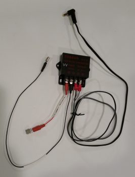
After testing the output of the AV8OR’s original wall mounted charger (5.196V) vs the 5V output coming off my 12V-to-5V converter (5.231V) and determining that the values were very close, I then connected the converter to 12V battery power through a 3A fuse. I then plugged in my Bendix/King AV8OR GPS unit and immediately saw the amber power in/on LED light up. The lack of smoke, fire or popping fuse was also a good sign . . . ha!
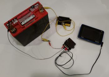
I then pressed the ON button of the AV8OR and it fired right up.
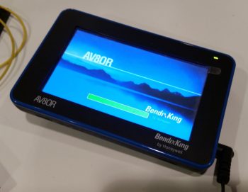
As with most GPS units, it took a few minutes for it to find its bearings, but it then perked up and functioned as normal. I’m very pleased to be able to have a hard-wired cord to use to power/charge this backup GPS unit without having to use up a cigarette charging port and contend with the bulky AV8OR car power charger.
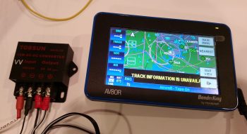
I then finally rolled up my sleeves and took a few hours to label my busses with the appropriate fuse size and a very truncated description that has just enough characters to tell me what the fused item is. Keep in mind that the labeling of these busses is for operational ease and quick fuse terminal position ID, possible troubleshooting, and/or system design updates. Although I was aiming for neat, orderly and legible, I am NOT trying to win any beauty contests here, nor win the “Straightest, most-aligned label of the Year” award!
I started off by knocking out the Battery Bus. Point of note is that after all these pics were taken, I did actually go back with bigger white on black labels for labeling the bus itself with “BATT BUS – BB”
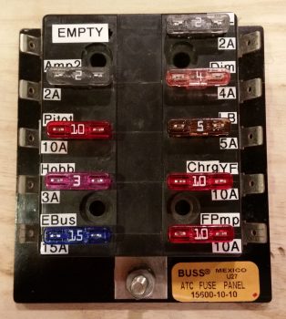
Since I’m focusing on labeling the front of the busses, I thought I’d include a pic of the actual side terminal labels, which is depictive of the other busses as well.
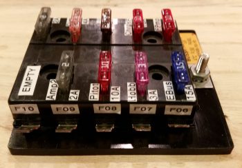
I then knocked out the Main Bus. If you have good attention to detail, you may note that the main bus has the fuse amp size listed above the fuse with the fuse circuit ID below it. I already had a bunch of these labeled so I left this scheme in place on the main bus. Not a huge deal, but I like having the actual fused component ID on the top for better visibility, so I changed it on the E-Bus.
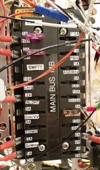
I went out for a bit to buy some groceries and make dinner, then afterwards I knocked out labeling the Endurance bus (E-Bus). Again, I also made a bigger white on black label and attached it to the center vertical area of the E-Bus just as I did for the Main Bus above.
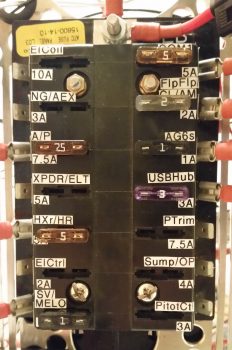
In closing I have one small, but significant, development to report. I had a good phone conversation with Marco today and during it I was conveying my frustration with the OAT readout on the MGL clock. Since the MGL’s degrees Celsius reading is an integer, with no decimal, it makes translating between Fahrenheit and Celsius a pain since the MGL is simply off a degree or two from the HXr EFIS due to this poor equational translation. If I could, I would merely shut off the OAT display on the MGL and be done with it.
This led to Marco asking if I had 2 GRT OAT probes and I responded I do, one connected to EIS4000 and one connected to the HXr AHRS unit. Note: this is essentially feeding two OAT data points into the same system, for simple redundancy. He stated that he has one OAT probe connected to each of his 2 Mini-APs and displays one on Fahrenheit and the other on Celsius.
Ah, ok, this still provides redundancy, but allows each EFIS to control how it wants the OAT displayed. To be clear, this is most likely possible no matter what or where the actual OAT inputs are located, but the point is that I have a dedicated OAT port on my Mini-X that –after some thought and assessment– I’ve decided now to employ for OAT probe #2 rather than mess around with it back in the D-deck/Turtledeck area. Since I wasn’t clear on how I was going to mount the aft OAT probe this puts that question to bed since the forwards mount into the nose wheel well (into NB) quite nicely.
Thus, I pulled the OAT wire out of the EIS4000 harness and updated all associated wiring and connector pinout diagrams.
•••
11 January 2018 — Today was still about cleaning up some panel electronics and getting some tasks crossed off the list.
First off, in my latest Mouser order I just received 2 new mini-toggle switches with flat bat levers (my preference) for switches #11 (Pitch Trim power) and #12 (Heated Pitot Tube on/off). Besides having 2 different brands of switches in the row of switches on my center panel column (see pic below), the switches that I replaced were ON-OFF-ON while these new ones are simply ON-OFF. No need to waste good switch capacity, especially when the switch levers were slightly different.
I started off by wiring the 18 AWG E-Bus lead to one side of the switch, then covered the solder joint with red heat shrink.
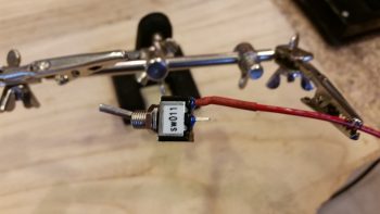
I then prepped the supposed two 20 AWG Pitch Trim power wires (as listed in the TCW Safety-Trim manual) for soldering, but then when I went to strip them found out they were actually 22 AWG. No big deal, just a point on how robust Tefzel aircraft wiring is in handling amps and heat.
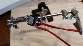
I then soldered the 2 twisted 22 AWG wires to the remaining post on switch 11. This switch is the “master switch” that provides power to the Pitch Trim system and exists mainly as a safety switch in case there’s a runaway trim situation.
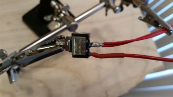
Here’s a shot of switch 11 (code sw011) remounted in the panel mockup with the soldered wires now attached. I’m waiting to terminate the 18 AWG wire with a FastON connector to then mount to the E-Bus until after my next shipment of wire labels arrive.
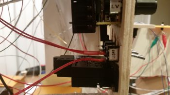
I’ve circled switch 11 in the pic below in green.
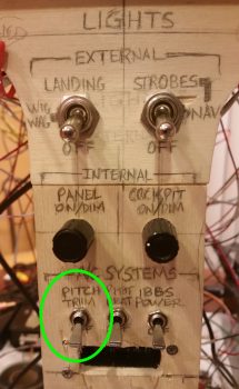
I then pressed forward with my plan to mount both GRT OAT probes forward in the fuselage, specifically in the nose gear wheel well (NB). I removed and then disassembled the GRT Mini-X wiring harness to slip the gray wire into the mix. Nicely, I was able to use the original OAT probe wire off the GRT EIS4000 harness that was already terminated with a D-Sub socket at the Mini-X end.
After I inserted the wire and reassembled the D-Sub back shell on the Mini-X side, I realized I should probably grab a shot of my progress. As I noted above, I’m out of wire labels but had just a long enough piece of blank white wire label heat shrink to hand write the label for this wire…. just so I could get it in and knocked out.
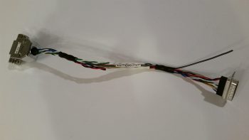
I then terminated the J3 connector side with a D-Sub pin and inserted the wire into the D-Sub connector. Again, below is a pic of the OAT wire addition task complete, with the J3 side D-Sub jack back shell back in place.
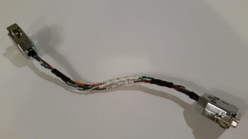
I then reinstalled the Mini-X wiring harness, fired up the panel and checked the OAT settings. I set the HXr on Celsius, set the Mini-X to Fahrenheit, then toggled the Mini-X setting to have the OAT show on the PFD page.
•••
12 January 2018 — I thought this string of 1N4007G Diodes that I just got in from Mouser would also make a cool pic and show you guys what they look like in “raw” form.
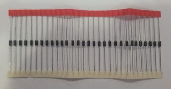
Here’s one of those diodes in action on one of the pigtails I added to 5 of the 9 panel On/Off indicator lights that allows me to tie into switch #4, the Push-to-Test button’s wiring harness. As I mention in the video (below) that I made to highlight the Push-to-Test button (and freshly wired dimmer) for these lights, I can only hook up 5 of the 9 lights to switch #4 for testing because the other 4 On/Off indicator lights contain closed systems…. where the configuration of the components that those lights report on do not support connecting them to the Push-to-Test circuitry.
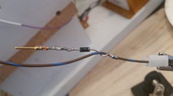
The added wire –in the form of a pigtail at first– to each light is nothing more than an alternate power source that provides 12V+ input to each indicator light connected to the Push-to-Test (PTT) circuit. The power provided by depressing the PTT button (switch #4) then flows to ground out of the other terminal of the light’s connector (via the dimmer switch).
Thus, I’m utilizing the diodes in the PTT circuitry (pigtails) on these lights as a one-way valve, preventing power being inadvertently applied to the other lights when only one has a real valid condition to cause the light to illuminate. For example, due to the way I’ve constructed the switch #4 wiring harness, if I didn’t employ diodes on each line then when I pulled the parking brake handle, which closes a switch allowing 12V+ power to run to the indicator light, the power would then back-channel through the pigtail (switch #4 wiring harness) and power up the other connected indicator lights. Obviously that would not be good, and as you can see these diodes prevent that scenario from happening.
Here is the same pigtail as above only covered with red (for indicator 12V+ power) heat shrink. One thing I should point out is that the connection to these panel On/Off indicator lights for the Push-to-Test circuits utilize D-Sub pins and sockets that themselves will be secured with heat shrink. I used D-Sub pins and sockets due to the fact over a myriad of configuration changes on the wiring system, I have spare wires terminated with these pins and sockets. In addition, I have a good number of spare terminated 22 AWG wires of different colors (shown on the switch #4 side of the equation in its mini wiring harness) from included GRT and TCW wiring harnesses.
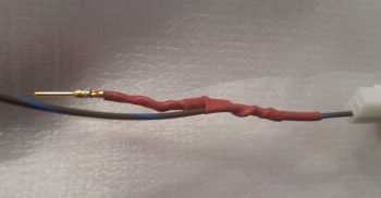
Just as I did on the panel On/Off indicator lights dimmer switch, I then determined the required wire lengths to the 5 lights that will be connected to switch #4 for the Push-to-Test circuit. I stripped the ends of these 5 wires of varying lengths and then soldered them all to the lead hanging off one side of switch #4 (the Push-to-Test button). The lead on the other side of switch #4 goes to 12V+ main bus power and since I didn’t know exactly how long this wire needs to be, I just terminated it with a cheap automotive connector for now. I then labeled the 5 terminated leads (4 pins/1socket) on this harness (I labeled the switch pigtail lead before soldering the harness together).
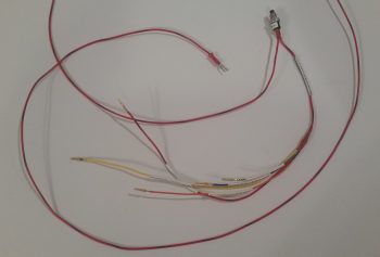
With my Push-to-Test switch & wiring harness complete, I hooked it up and tested it out. I was quite pleased at how both the dimmer and the Push-to-Test functions were working. So pleased in fact, that I decided to make a video, especially since it’s difficult to describe light dimming action, so I figured a video would help show it much better. I also briefly touch upon the new Engine function display page on the Mini-X that I just recently loaded.
•••
14 January 2018 — Last night at some point I was thinking about the actual physical wiring of the aft two cameras that each focus on a fuel site gage. I knew that before I could finalize my decision that I would have to test and verify that 24 AWG wire would provide enough juice for the cameras to send a good video signal.
What was gnawing at me was an issue of consolidation, and one of cable management. Dealing with 3 separate 24 AWG wires isn’t an insurmountable task, but I thought there might be some efficiencies to be had. I drifted to sleep with this on my mind.
Then there was the question I had this morning regarding those pesky LED lights on the fuel site gauges themselves. Hmmm, how will the wiring on these critters actually physically get run?
Then I had an idea. An idea that has eluded me for almost 7 years, considering Vance Atkinson’s fuel site gages are the first components I purchased, IIRC, for my Long-EZ project: What if I inverted them and put the LED on top? I pulled the installation instructions out to find, lo and behold, that the last line on the page –hand written– said that I could mount the LED on top OR bottom. Cool!
With that info in hand, I then planned initially –to be verified with some camera tests– to use a 5x24AWG conductor wire to handle both my aft camera and fuel site gage wire runs. Each aft camera would use 3 of these wires while each fuel site gage would use the remaining 2 wires…. again, all 24 AWG wires packaged nicely in one cable.
Since I don’t have any wire label stock on hand (they should arrive tomorrow) the first thing I did today was something else I haven’t done in almost 7 years, I tested the “red” LEDs (as listed on the included specs & install sheet) on the fuel site gages to find out that they A) worked, and B) are in fact actually white LEDs, not red.
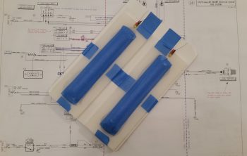
I then took about 45 minutes to get some low hanging and long overdue bits ordered. I finally found and ordered a couple of pieces of 1.5″ diameter heat shrink off of Ebay (I checked McMaster-Carr, WAY too expensive) primarily to encase/protect my relay that controls COM1-COM2 radio flip from the control stick. I also ordered a length of a rubber automotive seal that I’ll use for mounting the GNS480 GPS antenna puck cover atop the pilot headrest (after 20 min the ONLY source of supply for what I wanted was again off of Ebay, and straight from China no less).
I then got to work on my wiring diagrams to upend the Atkinson fuel site gages and depict their new orientation correctly. I also better depicted their actual physical wire runs and added in the visible segment of the 5x24AWG conductor wire. I have two diagrams, fuel system and cockpit lighting, that contain the fuel site gages so I tweaked one of them to the new “final” configuration and then merely copied over the entire new depiction to the other diagram.
I then spent a few hours doing something I haven’t done in a fair while: I created a new wiring diagram for the Video Camera Network. Here is a saved JPG version of that diagram. I was putting the cart before the horse slightly in that I hadn’t tested out the 24AWG wires –at least the non-shielded wire version– for the video cameras, but I was quite confident that it would work.
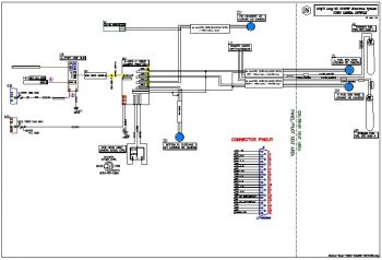
After compiling all the data I needed to represent the Video Camera Network wiring on a system diagram, I then set about testing my 24 AWG hypothesis. Fortunately, I found about a 7 foot length of the exact 5-conductor wire I want to use for the aft cameras, so this would be a great representation to check the video display quality using near the same length of wire.
I then stripped off the first couple inches of the outer insulator and grabbed 3 of the wires to hook up to micro-video camera #1 for testing. I soldered the wires to the camera leads off the tiny PCB board that the camera uses for 12V-to-5V conversion, and then hooked up the camera at the EFIS side. I fired up the EFIS and as you can see in the lower left inset, I got a very readable video display from the camera.
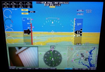
Since this camera is going to be used to view the fuel quantity in a fuel site gage, I amused myself (yes folks, constant electronics will drive you stir crazy!) by placing the still-wrapped site gages in the video camera’s view to snap the pic below.
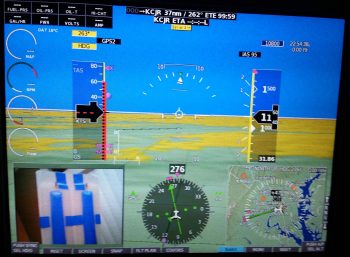
I then spent a good 20 minutes desoldering a connector off a PCB board (I stole it off the defunct 5v GNS480 indicator light that burnt up) and then soldering three 22 AWG wire leads to it. I then connected my 5V “wide angle” video camera #3 up to the EFIS and 12v-to-5v converter to test it out. As you can see below, although not nearly as “wide angle” as I was expecting, the video display quality is fine.
Now, I noted that a few of my 5V components go from 5V+ power on the positive lead then simply hook up to standard 12V ground on the negative lead. Since these cameras depict and physically have a both a positive and negative side for the video signal (via the yellow RCA jack) and on the camera power input (via the red RCA-type jack) I figured each component needed a direct connection to ground. I noted this concept was supported in Eric and Alec’s design of my 4-into-1 video signal sequencer, since on the unit’s D-Sub connector they placed a signal ground pin right next to and for each video signal input pin. Moreover, also on the unit’s D-Sub connector they had a pin for camera power and another for camera ground. Ok, so that’s how it needed to be wired (allegedly).
But back to my 5V ground vs 12V ground, as I was testing the grounds on camera #3, I pulled the ground off the outer ring of the video signal RCA jack which resulted in ZERO impact to the video signal. It was still right there on the screen. In fact, I moved the camera just to ensure no weird screen capture event had occurred.
Hmmm, interesting.
Ok, so then I disconnected the ground path to the 12v-to-5v converter. The EFIS video inset screen went blank. I then tried re-hooking up the ground to the outer ring of the video signal RCA jack…. still no video signal. Reconnecting camera ground brought the video back live again.
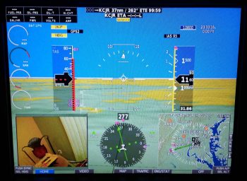
So the 2-ground requirement I had noted in the camera install manual does not seem to apply, at least for seeing the video signal. I’ll have to double check in the manual to see if it keeps the unit from errant electrons or something. Moreover, I tested this on camera #1 by hooking it back up and found the exact same results: no ground lead required on the video signal RCA jack. Not a huge find in how it impacts the amount of wiring effort, since it merely eliminates 3 small ground lead pigtails… but it is nice to know.
I depicted this on my new Video Camera Network electrical diagram and with confirmation that the 5x24AWG conductor wire will work I then labeled all the wires with the appropriate wire colors.
•••
15 January 2018 — Today I got my wiring labels in fairly early and I immediately started knocking out my list of wire labels. All told I attached well over 30 labels today. I am close to running out of wires to actually label in & around the panel area . . . and that’s a good thing!
I was also able to finally finish wiring up the EFIS GPS to the Trio autopilot cross connect wire that I jury rigged about a month ago in finding the fix for the Trio AP not getting a GPS signal from the EFIS. I never actually installed the circuit for final implementation, so I did today.
•••
16 January 2018 — A lot of what I did today was cleanup or finalization from the original install of these components in my panel mockup. Since I used the panel over multiple months, I was both happy with the design of it and comfortable with the flow. Except for some 1/4″ shifts max everything looked to be pretty much set as it would be in the airplane.
My first order of business was to solder in 2 lengths of 20 AWG wire (BLACK) for a new GNS480 ground wire(s) run. First, as per my original plan my 2x 20 AWG power (RED) wires run forward from the aft plate of the GNS480 to the front lower LEFT corner of the panel (behind the panel), then from there traverse across the panel just above the leg holes to the 5A circuit breaker in the lower RIGHT corner of the panel. Then one single 16 AWG wire exits the other side of the 5A CB, flows back to midpoint of the panel, then straight forward to the “Deslumpifier,” as depicted below.
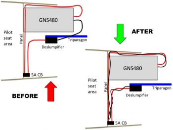
After soldering the longer lengths of 20 AWG black ground wire into place, I then labeled the wire as a pair and then ran it from the GNS480 unit to the Deslumpifier, while twisting them with the power wires. The GNS480 power wires are decent sized wires, so I should have thought of this initially when I installed the unit and took steps to mitigate any EMI/EMR noise then. The main reason I soldered in lengths of wire vs just running brand new wires was the terminated ends that I didn’t want to waste, especially the right-angled PIDG FastONs that are a bit pricey. In short, it was just easier and cheaper to solder in a couple of long new wires.
I then targeted the Trio autopilot wiring harness and finished labeling all the unlabeled wires in it. The effort on the Trio autopilot also required me to add about a 6 ft extension of twisted pair of green and orange 22 AWG wires to the existing twisted pair exiting out the harness of the Trio autopilot for connection to the FT-60 Red Cube Fuel Flow transducer in the Hell Hole. Once I cut and twisted (using a cordless drill) the new fuel flow extension wires together, I then soldered spliced them to the end of the fuel flow wires exiting out of the Trio autopilot. I then added a few labels to the entire run of new twisted pair and called that task complete.
I added I would say at least another 30+ wire labels, both in minute recesses of the panel wiring that I had missed, or in the the new wiring schemas I was implementing today. I have to say that, except for a final, no-kidding check on the AG6 warning annunciators, CO meter, and TCW Start Smart module, with all those wires at least ~70% labeled currently, I could install the panel as-is today and be happy with the wire labeling and interconnectivity. What I wouldn’t be happy is with the cable management, which is something I am going to undertake soon to start wrangling all those cables into a nice orderly fashion.
Another puzzle piece I had to figure out was all the OAT probes, specifically the ground points for them. I have one OAT probe connected to the GRT HXr AHRS, one connected to the Mini-X (new design change from the EIS4000), one OAT probe that connects to the HXr but serves as an air/heat duct temperature gauge, and one OAT probe off the MGL clock. I did some research and figured that with the signal voltage on these guys being so low (for example, the MGL uses 30 ga wiring) that I would simply tie all the OAT probe grounds in at one point on the G5 Avionics Ground Bus. I was actually shooting to tie all the OAT probe grounds into the lower, forward G4 Panel Ground Bus, but there’s a specific statement in the GRT manual to keep the OAT probe leads twisted as much as possible to optimize the signal from the sensor. With the G5 bus being higher and farther aft on the Triparagon (i.e. closer to the positive signal wire ports of the respective OAT probes) I chose it as the best grounding point.
So that’s what I did. Below you can see the 3 GRT OAT probes’ ground leads tied into one lead (lower right corner) ready to be connected to the G5 Avionics Ground Bus. I labeled all the OAT probe wires and terminated the ends to match their respective tie in ports (all D-Sub: AHRS harness, J4A connector, and J3A connector). Since my MGL Clock OAT probe is still on “probation” and subject to being swapped out if it’s numbers (temp accuracy) doesn’t improve, I simply left a pigtail hanging out of the ground harness below to tie in the MGL OAT probe. Once that issue is resolved, I’ll solder in the MGL OAT probe ground wire and heat shrink the splice. [BTW, the GRT OAT probe leads do NOT come twisted… I had to do those by hand so as not to damage the sensors on the end of the leads].
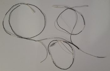
•••
17 January 2018 — Today I spent a couple of hours researching and doing some initial messing about with configuring my engine data info display on my HXr EFIS screen. After seeing and assessing how I can go about configuring it, I got into the manual to find that I missed a HUGE piece of the installation puzzle . . . again, assumptions will bite you in the butt!
Since the EIS4000 is a standalone panel mounted instrument in its own right, but that can also be summarily hidden away so it’s sexier cousin (HXr) can get all the praise in presenting such wonderful data in bright shiny ways, all the parameters on the EIS4000 must be zeroed out with all the engine data max/min limits set in the EFIS. Why? Well, if an alarm rings off on the EIS4000 (remember, it’s a standalone instrument that shares its data with the HXr EFIS) with it tucked behind the GIB’s head, then there is no way to turn the alarm off!
Thus, by zeroing out the engine data parameters in the EIS4000, it then becomes an information collection point and conduit to further pass the data (and parameter limit control) to the HXr. So along with deciding what exact info I want displayed, and how, a new task on my list is to now transfer all the engine data parameter limits from the EIS400 to the HXr (and Mini-X) and then zero out the engine data parameter limits on the EIS4000 box (except for the Aux functions… those are simply replicated between the two units).
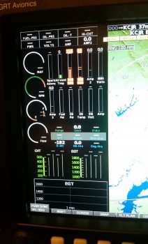
•••
24 January 2018 — Today I called GRT to solve the case of the missing EGT & CHT probes, which they are sending me the sets for my engine (an oversight on their part, but they are remedying it in an expeditious fashion).
Moreover, for this discussion, one of their EIS techs, Eric, was great in providing me a tech sheet on just how to hook up my #3 GRT OAT probe to use as an air/heat temp sensor inside my air/heating ducts. A couple key issues is that I needed to use a 4.8V excitation signal from a 5V source (luckily I now have that at the front side of the aircraft) and I needed to solder in a 10K Ohm resistor on a pigtail that went from the signal wire to ground. Once I did that, Voila! … it was up and running. With just one minor tweak of the Scale Factor setting and I was in business.
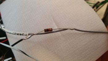
After I soldered in the 10K Ohm resistor on the ground pigtail, I then covered and secured it with heat shrink.
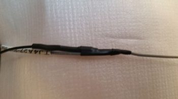
I then got to work on setting up my engine data display on the HXr EFIS. I’d like to point out a few things in the pic below. First, note column #3 “Airvent Tmp” and column #5, “Spark Advnc” in the lower left inset. Next, note the yellow “L Sump LOW” and “R Sump LOW” alarm states across the top, which not currently being hooked up to the low fuel sensors they alarm due to no signal…. I also got some more refined info on dialing in these Sump Low Fuel alarms from GRT as well. Finally, note that in column #1 I have a low voltage alarm on EFIS Voltage 2, which is the E-Bus feed to the HXr.
Since not all data points are available to each display area. For example, the vertical data columns in the inset don’t necessarily have the same data points to display as say the 4 black combo boxes stacked up in the upper right corner of the inset. I played around with these a while until I finally got the data showing that I wanted.
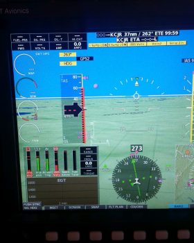
I then went to the split screen engine data page. Note that my #2 EFIS power input is still red in the pic below. Also note the new red numbers in the EGT and CHT graphs at the bottom, which is showing up since I set the limits.
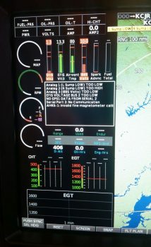
I finally took a moment to see why my EFIS Volts2 input source was alarming, and quickly discovered that I had no fuse in the E-Bus slot where the HXr connects to… so I popped a fuse in, and no more alarm. However, I would like to point out even further the bus power source data below. Column #2 in the inset is EFIS Volts3 power input which comes from the X-Bus, or IBBS. Now –since the IBBS is not installed– it’s simply jumpered off the Main Buss, so those two busses read the same: 13.3V. But the E-Bus voltage reads 13.0V. Why? This is due to the Schottky diode that lies in the middle of the connection between Main Bus and E-Bus. Schottky diodes extract a toll for their services, often up 0.7 of a volt just for being in the picture.
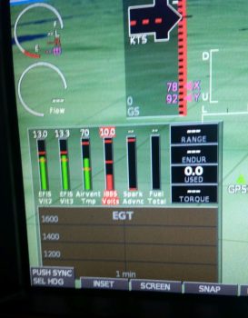
After setting all my engine data limits, inputs and parameters in the HXr, I then did the same in the Mini-X. I made a few quick changes right off the bat like changing out the Carb temp reading in the upper LH corner to “MPG.”
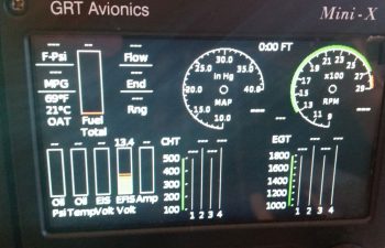
I then did a bit of exploring and found a few cool things: such as the 6 different engine page display types on the Mini-X.
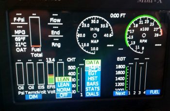
Here is DATA menu #2: EGT as shown above that I selected. I also set some display parameters like dropping down the max RPM on the dial from 3000 to 2800 RPM. Note that it will still display the actual numerical RPM if it goes above 2800 RPM (the dashed lines at about the 4-O’clock position of each dial), it just doesn’t show it on the dial. The reason for narrowing the dial’s range is that it actually makes it more readable since it increases the granularity on those setting numbers displayed (i.e. makes the space bigger between the numbers) in the normal operating range. If it goes above say, 2700-2750 RPMs, it will definitely let me know!
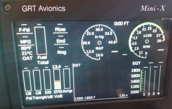
Here’s another page: STATS.
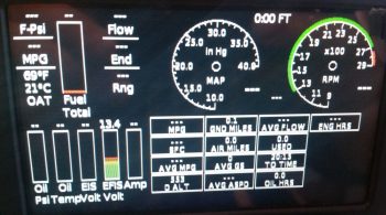
And lastly, a dials page that adds % power and fuel flow in dial format.
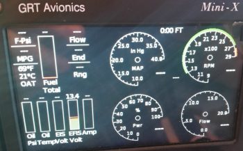
After spending a bit of time configuring all the EIS display settings and inputting all the limits and parameters, I then zeroed out all the limits on the actual EIS4000 box. Thus, until I fire the engine up and taxi around, I’m pretty much done with programming engine data stuff on the EIS. It will truly be just a matter of fine-tuning the numbers from here on out.
•••
28 January 2018 — Today I got busy building a couple of cables… the first one is 1 of 3 cables that need to be constructed for my video cameras (left, right and top). The left and right video cameras share a 24 AWG 5-wire cable with the fuel site gage LED power wires. The total is 3 wires for the camera and 2 wires for the LED.
I grabbed the first camera I bought last year and ensured it was ok since I had tore it up a bit removing the plastic shell around the inline mini PCB. A week or so ago I had quickly soldered some wires to test the non-shielded wire version of this cable, which as a reminder worked much better than the shielded wire version where I had the camera grounds (video & power) running through the wire shield with not-so-great results (my thought is there was too much resistance in the shielding).
I removed the test solder junctions, cleaned up the wires, added heat shrink on the wires and then re-solder spliced the wires. I then heat shrank all the solder splices.
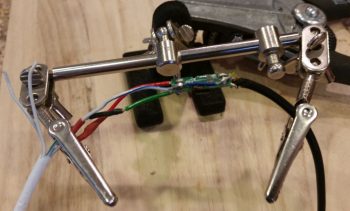
After getting the video camera’s wires solder spliced and squared away, I then added a bigger piece of heat shrink to protect the whole video camera-to-5-wire cable junction, leaving the 2 fuel site gage wires exposed of course.
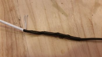
Then on the hot lead for the fuel site gage LED I added a 470 Ohm resistor.
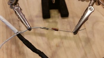
And then soldered it in place.
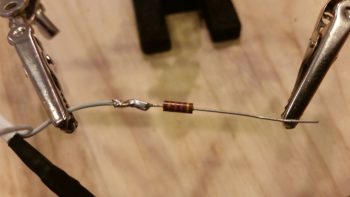
I then solder spliced the 22AWG white with red stripe power lead to the 470 Ohm resistor. I added the resistor on the line here at this junction because I felt that it would both better be protected at this point, and plus I didn’t want to have to contend with it at the actual connection point with the fuel site gage LED light lead.
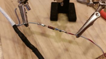
I then added red protective heat shrink over the fuel site gage LED light’s 470 Ohm resistor and the adjacent wires.
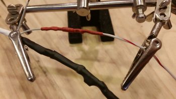
I then solder spliced in a white with black stripe 22 AWG wire for the fuel site gage LED light’s ground return lead. The lead wires on the opposite fuel site gage LED light will simply be red and black, so this will help in distinguishing the 2 sets of leads.
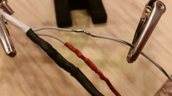
I then added heat shrink to the fuel site gage LED light’s ground lead.
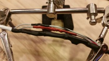
I then added one more piece of heat shrink over the entire fuel site gage LED wire leads and the video camera connection to the 5-wire cable.
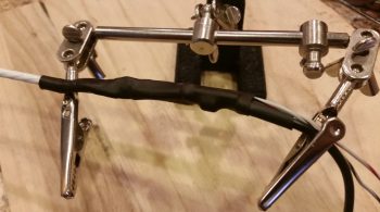
I then got to work on the panel end where I solder spliced in the ground lead for the fuel site gage LED light.
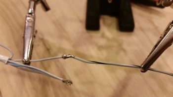
And then did the same on the fuel site gage LED light’s power lead.
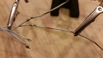
I then added heat shrink over the solder splices on the two fuel site gage LED light leads.
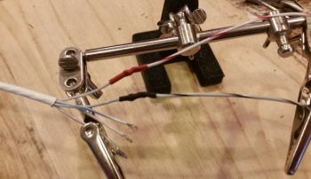
Also on the panel end of the 5-wire cable I soldered wire leads for the video camera, using the original standard color scheme that is employed for video cables: Red for camera power, black for camera and video signal ground, and yellow for video signal.
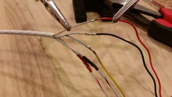
I then added heat shrink to all the video camera leads’ solder splices.
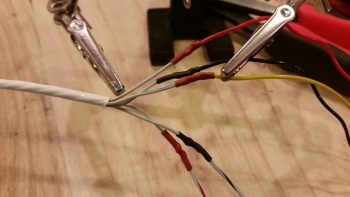
And then separated the two groups of wires: video camera and fuel site gage LED, and then added respective heat shrink to both sets of wires.
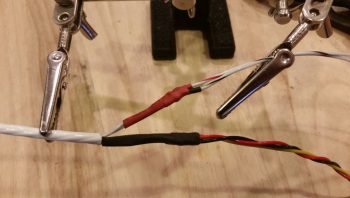
And then finalized the cable with a larger piece of black heat shrink. Yes, I know accounts of cable building is not exactly riveting to read about… nor are these an overwhelming hoot to build. It actually took well over an hour just to construct this one cable. But again, they are very necessary for what I want to do and I’d rather get them done while the weather is still colder.
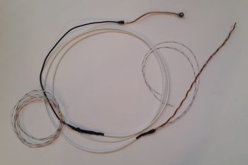
•••
4 February 2018 — I started today by relabeling the power busses upon where I had mixed up the connection assignments to move my IBBS from the main bus to the E-Bus.
I then moved on to try my hand at something I have not yet done on this build, or ever quite frankly: wire lacing. I started this journey by removing the Mini-X wiring harness to use it as my first guinea pig.
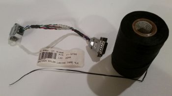
Here are a couple of shots at my first attempt at wire lacing. Not bad I’d say, and it definitely will do the job.
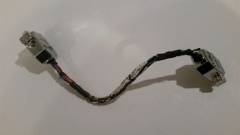
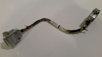
I then went back to the panel mock up and removed the GRT HXr EFIS wiring harnesses. On the B connector I relabeled a couple of the wires and then terminated and added a new wire. Besides relabeling a couple of the wires used for the auxiliary analog ports, the new wire I just added is a cross connection between the HXr and the Triparagon-mounted J4 jack for the last unused HXr analog port… just in case I want to use that spare port for something later on in the future.
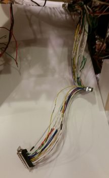
I then cable laced the first leg of the HXr wiring harness.
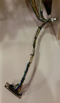
And then eventually got through all the separate legs of the HXr wiring harness, before finally bringing them altogether as much as I could in one grouping.
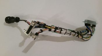
Here’s another shot of my last official task of the evening: cable lacing the HXr wiring harness.
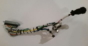
•••
14 February 2018 — I took a break in early February to deliver another load of household goods down to my storage unit down in North Carolina in support of my upcoming move there later 2018. On the way back home to northern Virginia I stopped by to spend a couple of days with my very good friend & fellow Long-EZ builder Marco and his lovely wife Gina.
During my visit Marco very graciously opened up shop to help me in lathing 4 aluminum standoffs for 2 of the 3 GNS480 GPS antenna connectors (2 standoffs per each antenna connector). After talking to the guys at Stein Air a few months ago, I took their advice and ordered some 1/2″ high 4-40 threaded hex standoffs from McMaster-Carr but then for some inexplicable reason forgot them at home during this trip. Since I had one of the original hex standoffs with me, Marco and I were able to figure out the configuration and use a simple aluminum rod to lathe the 4 antenna standoffs out of it.
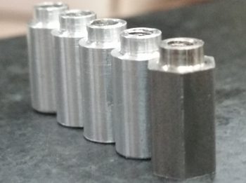
It took a bit to get the configuration dialed in, but once we did, Marco worked his magic and had 4 standoffs knocked out in fairly short order.
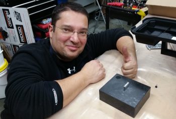
Here’s another shot of the original hex GNS480 antenna standoff and the 4 new aluminum standoffs.
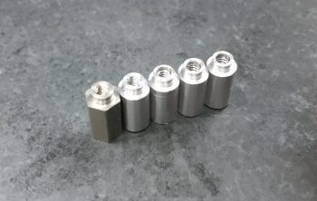
•••
18 February 2018 — Today I updated my GRT Mini-X’s software and downloaded all the new Seattle Avionics chart and approach plate data. Plus, I updated a few checklists on the HXr.
•••
26 February 2018 — Today I destroyed one of my dimmers.
Below is the subject dimmer. I pulled the photo of this dimmer unit off of Stein’s site, although I did not buy this specific dimmer from Stein. I wanted this pic because it shows the SOUSOO (“Sockets of Unknown Style or Origin”) in the lower right corner. Actually, I can spot right off that the terminals in this pic are different (read: standard)than what came with mine, which NONE of my plethora of crimpers worked on the very odd esoteric terminals included with my dimmer.
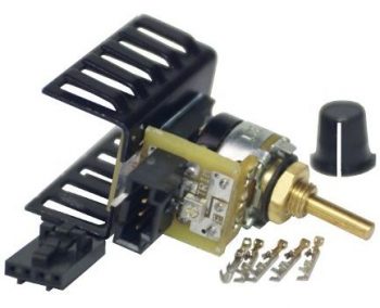
I want to start off by saying that mistakes, redos and rework is often the bane of the homebuilder. Moreover, although sometimes there are issues with the products, I am very, very happy that people make products at home to sell to (other) builders. Now, that being said, I am NOT a fan of this dimmer. Or more specifically, the mechanics required surrounding the installation of this dimmer.
The instructions were vague enough that I got the terminals –which were all grossly disfigured to start with after my multiple attempts to crimp simple 22AWG wires to these frail terminal bodies– installed backwards . . . again there was no clear instructions on which crimper to use (etc.).
Thus, when I hooked it up and tested it on an LED, it didn’t work. Then after taking some readings with my multimeter, I realized it was all in reverse. Ok, I’ll just cut the lines and resolder the leads back on in reverse. The crimps were so bad/frail that the wire-stripping process on the red power wire broke the socket in half, merely yanking the half-terminated wire right out of the terminal socket. On the black ground wire it wasn’t quite as ugly, with the wire simply and cleanly exiting the terminal altogether, leaving it in the connector block.
So, with no usable connector and no extra sockets (I couldn’t have extricated the broken or stuck terminals anyway), I simply broke the plastic housing away on the dimmer itself to expose the 4 male pins to allow me to solder the wires right to the pins.
Improvise, adapt and overcome… right?!
Well, in my continuing comedy of errors, I noted on the first two pins that the solder was just not wetting out well. Sometimes it can be a little finicky, but I will note for the record that the risk of using a soldering iron with the heat dial on the handle is exactly what happened here: it was turned down about 100° C off max (which is required on this soldering iron). This meant my “dwell time” in fiddling with getting the solder to wet out was 2-3 times longer than it would have normally been.
No biggie (I was unaware of this at the time… so ignorance was bliss for about 15 minutes), since I found the issue by the third pin and quickly resoldered the first two pins. I then covered all my good solder joints with some nice heat shrink and all looked ok. Here’s the finished dimmer wire connections, round 2.
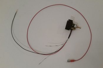
And a closer shot of the soldered wire connections.
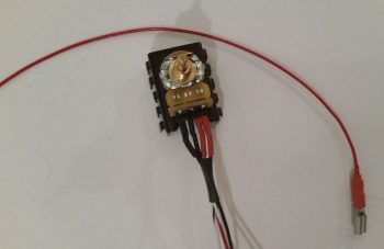
I then remounted the dimmer in my panel mockup, connected the power, ground and LED test light leads and fired up the panel. Nothing. I tried and tried different configurations, popped 2 (more) fuses in trying to get voltage readings off the tiny board…. and eventually pulled it off the panel to inspect it.
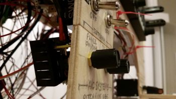
In inspecting the PCB, it looks as if my soldering dwell time (we’re talking 6-8 seconds vs 2-3 seconds) actually caused some cross-flow of solder on the board itself. A bit unusual for what I’ve experienced, but it’s the only thing I can figure out, because after 20 minutes of messing around with the dimmer, it was still simply INOP.
Thus, I’ll save the heat shrink as the most expensive heat shrink I’ll probably ever buy, and order a new dimmer…just not another of this make, but rather another one of these:
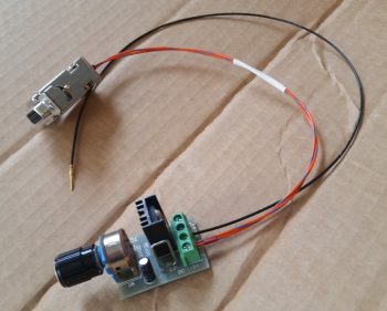
I’m not a fan of hoity-toity, fancy-schmancy esoteric connectors that are difficult to work and frail in construction. For something along the lines of a dimmer I’ll use screw post terminal blocks any day of the week and leave the “cool stuff” where it belongs, in the garbage can.
•••
27 February 2018 — Today I started out by wiring up the instrument panel dimmer that handles the dimming for the Trio Autopilot, TruTrak ADI, Vertical compass card, both AG6 Warning Annunciators and possibly the Dynon intercom.
As you see in the pic below, the setup and wiring of this dimmer is much more user friendly than the dimmer I trashed yesterday, with the wire ports on this one clearly identified.
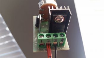
After wiring up the dimmer above, I then took a short video to provide an overview of both dimmers. So without further ado, I’ll let the video tell the rest of the story:
•••
7 May 2018 — Today a package arrived from Aircraft Spruce. This was one of those special deliveries since it included the last of the major panel components that I’ll need to actually operate the aircraft through my 40-hour fly-off: the Trig TT22 Mode-S Transponder. Now, I will be picking up a remote-mounted HXr-controlled backup radio as my COM2 and also a ACK E-04 ELT well before first flight, but clearly my to-buy list for avionics/instruments is down to just a couple items.
Opening the transponder box I could tell immediately that it was a high quality item with nice ring-bound manuals and a high-end accessory kit. It amazes that besides TSO’d equipment, as homebuilders we often get high-end, high cost components that are packaged and equipped as if we had bought them second-hand off of Ebay!
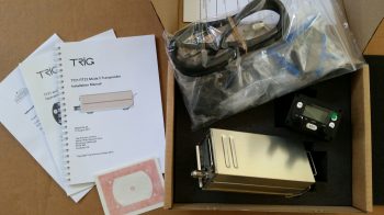
I grabbed the Trig TT22’s awaiting 2-digit electronics code label and affixed it to the top of the box, then placed the unit in it’s allotted location at the right side of the Triparagon’s top shelf, immediately adjacent to the HXr’s GADAHRS unit. As a point of note, since I purchased this unit from ACS vs GRT it came with the panel mounted control head which I will NOT be using. Moreover, I’ll need to incorporate a serial adapter from GRT that allows the HXr to control the transponder remotely and thus negates the need (and actually it can’t work with both) for the panel mounted control head.
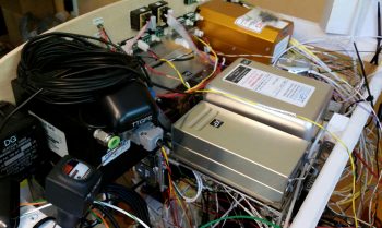
Here’s a shot of the two cohorts in crime atop the Triparagon’s cross shelf. Note that neither one is actually mounted to the cross shelf yet.
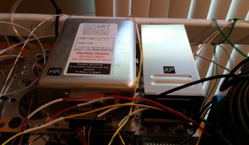
•••
18 December 2019 — Today I started down the road of mounting the Trig TY91 remote COM2 radio, the GRT HXr AHARS, and the Trig TT22 Mode-S Transponder to the Triparagon top shelf.
Since the weather has turned somewhat and it is quite cold during the mornings, I thought I would let the workshop warm up a bit before venturing out and working on it. And not surprisingly, I’m quite tired from the endless days of working on the shop. So I thought I would take the morning off to work on the plane just a bit. It’s been a while!
Of course, the easiest way to mount this stuff to the top shelf of the Triparagon is to remove the shelf itself. The physical removal of the top shelf is the easy part… getting it unencumbered even with the scant amount of stuff it currently has mounted on it is a bit more time consuming.
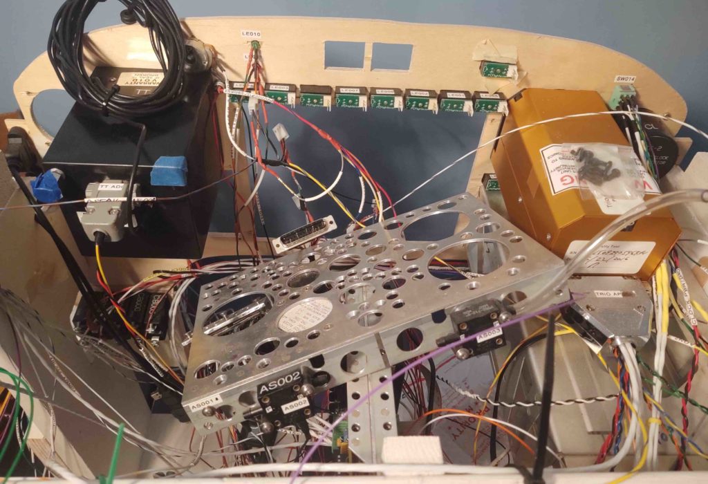
Attached underneath is the gear/canopy warning horn as well as the JBWilco gear/canopy warning system module. The tricky part here is simply keeping track of the small screws, washers and nuts after removing this stuff.
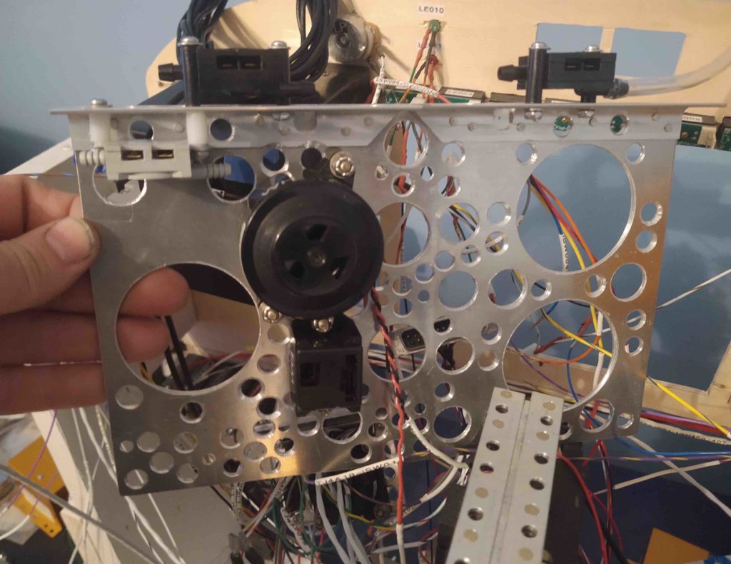
Then came the airspeed switches. Same thing… I want to ensure this all goes back together nicely and easily!
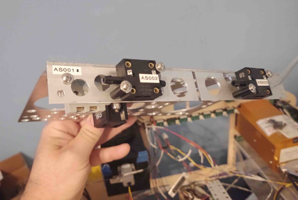
Here’s a shot of the JBWilco gear/canopy warning system module and the 3 airspeed switches.
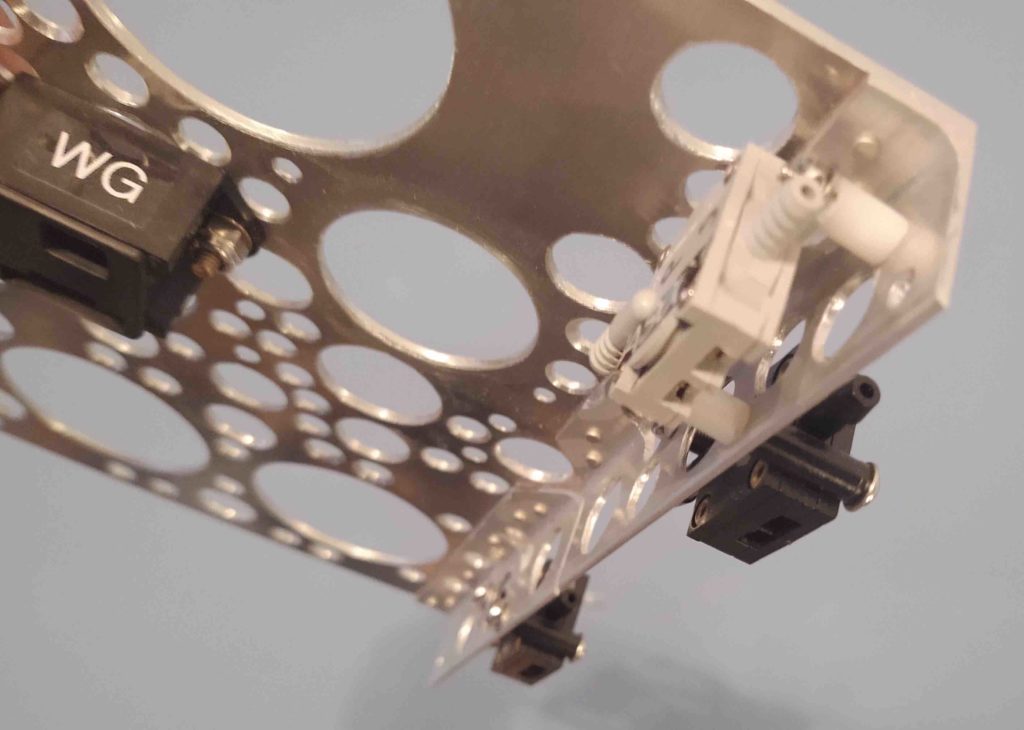
Once the Triparagon top shelf was free of stuff, I could then get to planning out just how I was going to mount these 3 devices.
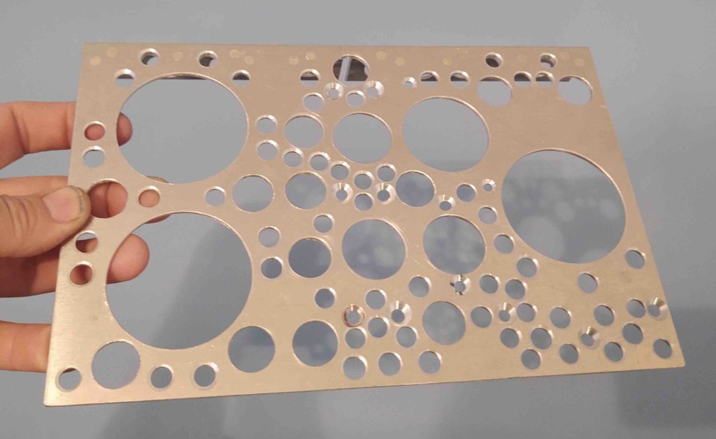
You’d think mounting 3 components to this top shelf would be a fairly simple and quickthing to do… but finding all the hardware, after deciding what you’re going to use, after figuring out what will fit, etc, etc, etc. . . . Wow, a couple of hours had already flown by after I rounded up all the hardware I was going to need.
Let alone figure out how to mount the two Trigs.
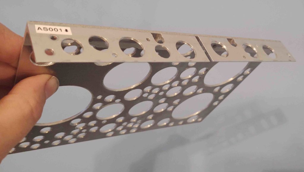
Why are the Trig components a question? Well, as I mentioned before in previous posts, I had not planned on using the Trig TY91 COM radio —but rather the MicroAir M760REM–when I finalized my design for the Triparagon over 3 years ago. Specifically, the top shelf where the TY91 is going to be mounted since the MicroAir was to be mounted underneath in order to, if you’ll recall, save space and minimize the width of the Triparagon’s top shelf.
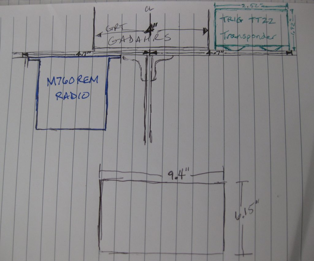
Moreover, since I “Swiss-cheesed” the Triparagon top shelf to save weight, I effectively removed all but one possible mounting point of the 3 required for the Trig TY91’s mounting adapter. Thus, I needed a decent-sized metal plate that will go on the underside of the top shelf to serve as the bottom-half clamp portion opposite of the actual TY91 mount on the upper side of the top shelf. As I was looking for the unused mounting plate for the EFII fuel boost pump since it was the perfect thickness (which I couldn’t locate) I found this old ELT antenna base (or maybe actually for a transponder?) that I constructed back in Germany.
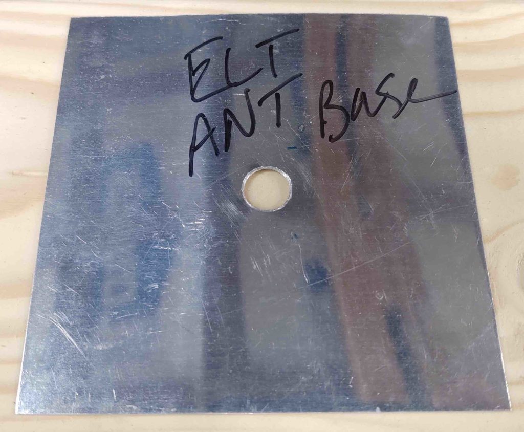
With my L2 transponder antenna in hand and since this is not required for my ELT, I know I’ll never need this antenna base as constructed. It’s a nice thin, yet strong, piece of aluminum so I lopped off the portion I needed and will use it to mount the Trig TY91 remote COM2 radio unit.
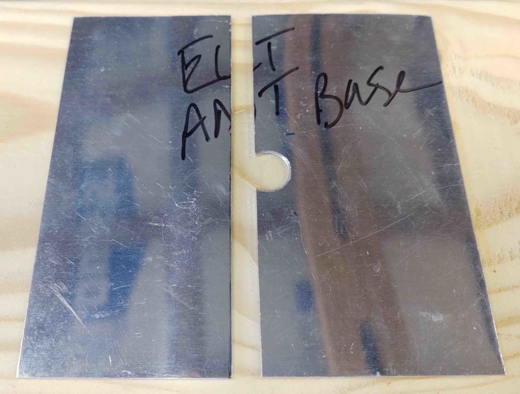
As for the Trig TT22 transponder mount… a few days ago while I had the chop saw out working on the roof I grabbed the stock of 2.5″ x 2.5″ x 1/8″ thick 6061 aluminum angle that I just recently ordered from Aircraft Spruce and cut it at just a hair over 4″ long. I would have preferred 0.063″ or maybe 0.090″ thick over 1/8″, which is a bit more robust than I need. But to get the 2.5″ width required this was all they had. Of course after I add some lightening holes it won’t be overly weighty anyway.
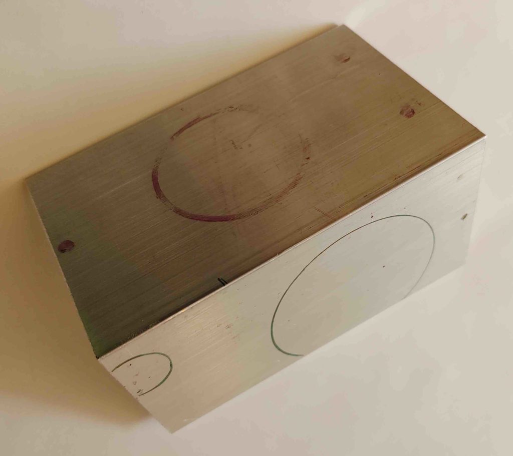
To remove as much unnecessary material as required, I angled the horizontal side that will be mounted to the underside of the Tripargon top shelf. I’ll do the same for the vertical side that the transponder mount will be attached to. Again, I’ll then make some decent sized lightening holes to get this as light as possible.
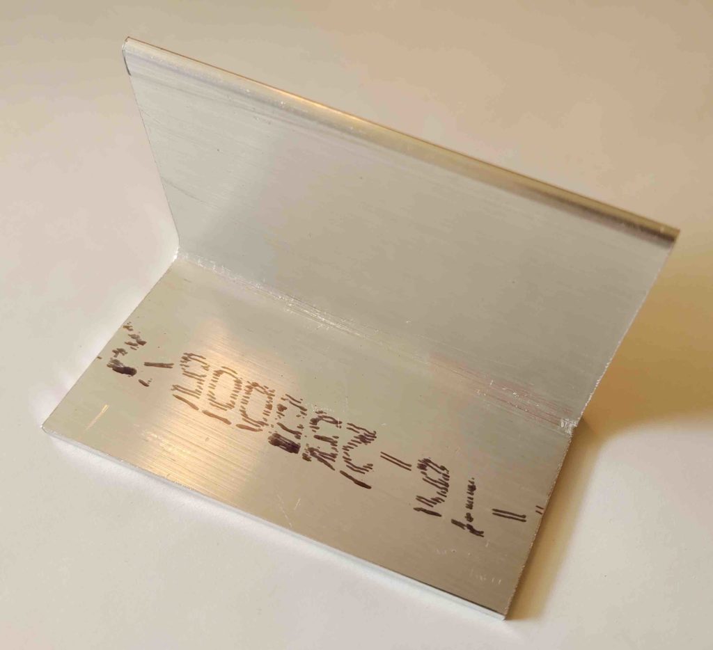
As a reminder, this bracket will allow me to mount the Trig transponder on the right end of the Triparagon top shelf. In the pic below the panel is left and the nose is right. Also, the bottom half of the AHARS is visible in its position at the center of the Triparagon’s top shelf.
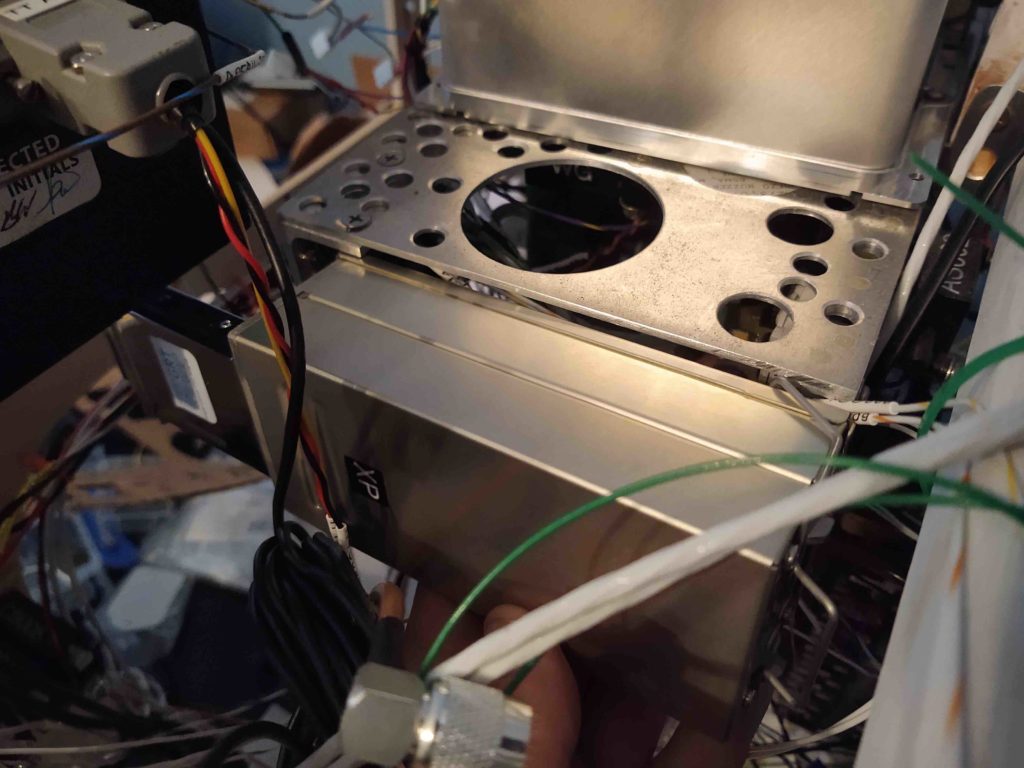
19 August 2020 — Today I got to work mounting the GRT AHRS to the top shelf of the Triparagon. On the aft side of the shelf I used 2x #6 nutplates.
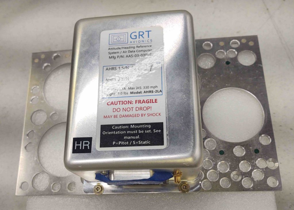
Due to the lip on the front of the shelf, I’m simply using 2x traditional nut & bolts.
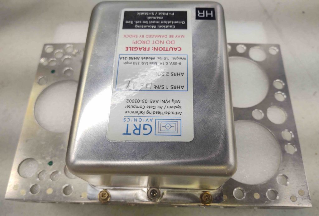
The bottom side shows all this more clearly.
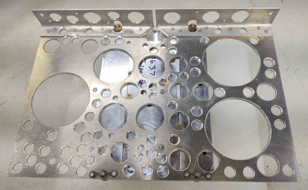
•••
21 August 2020 — Today I set my sights on installing the Trig TY91 COM2 radio, which sits just left of the ARHS.
If you remember, I had planned on installing a MicroAir remote radio, which not surprisingly had a different footprint than the Trig TY91. The simple fact is I have ZERO metal available to me on the Triparagon top shelf to mount the Trig TY91’s mounting bracket to, so I’ll employ a thin piece of aluminum (former life was transponder antenna backplane) as a clamp for the COM2 radio bracket.
I started by spacing and drilling the holes, and then riveting the nutplates into place.
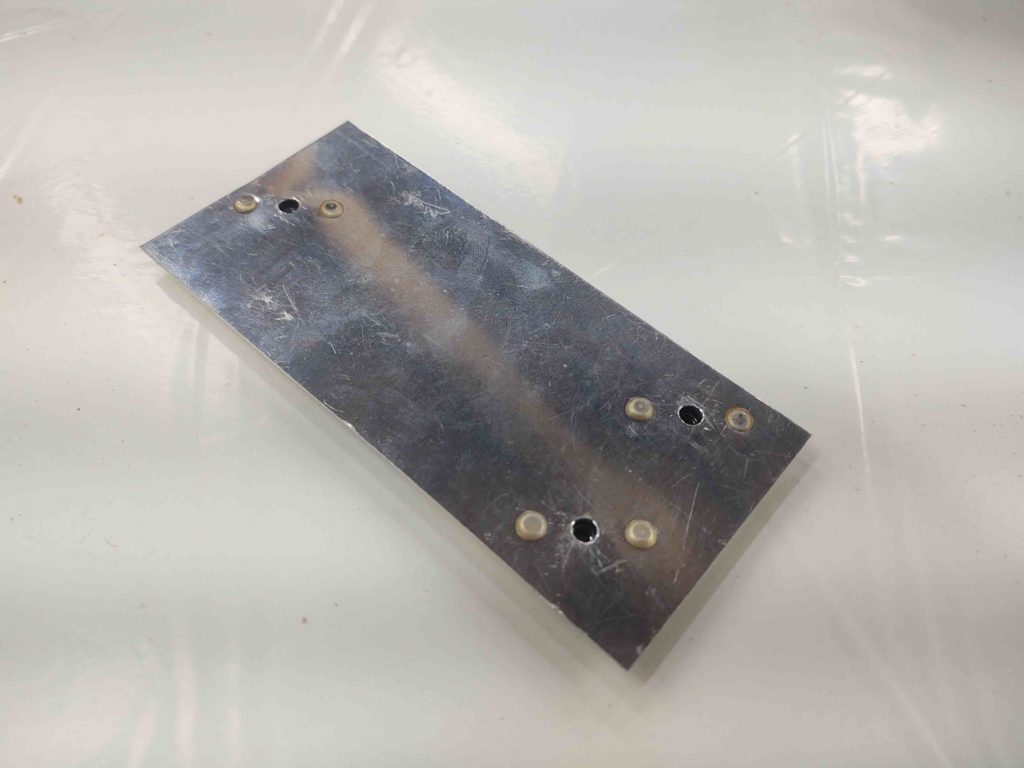
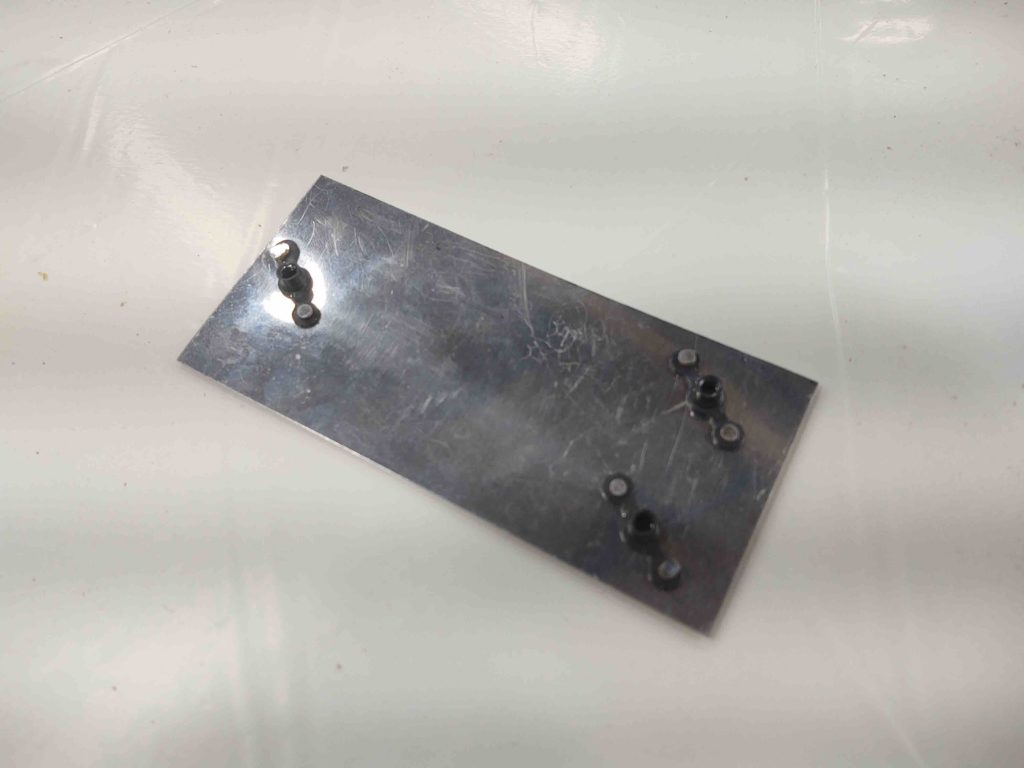
And then simply placed the Trig TY91 bracket on the top of Triparagon top shelf, with screws attaching it to the compression plate located on the bottom of the top shelf.
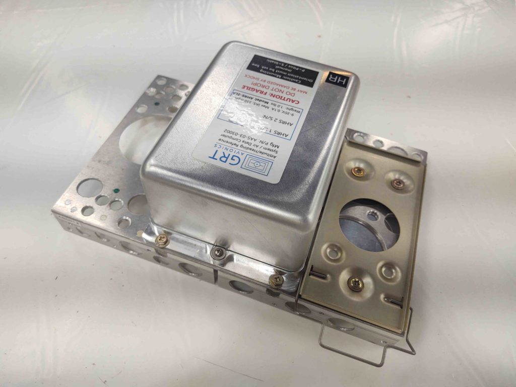
Worked a treat!
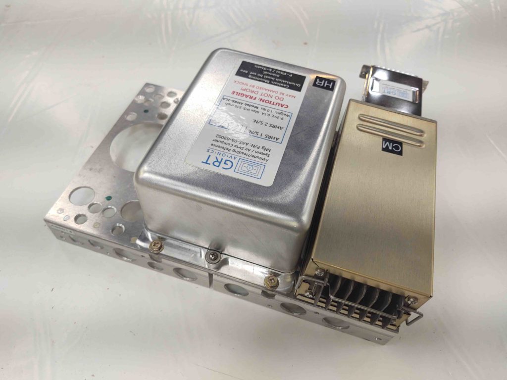
Next up will be the Trig TT22 Mode-S transponder install on this top plate. However, as I pointed out earlier, due to interference with panel instruments I’m mounting the TT22 sideways on the right side, hanging down for clearance.
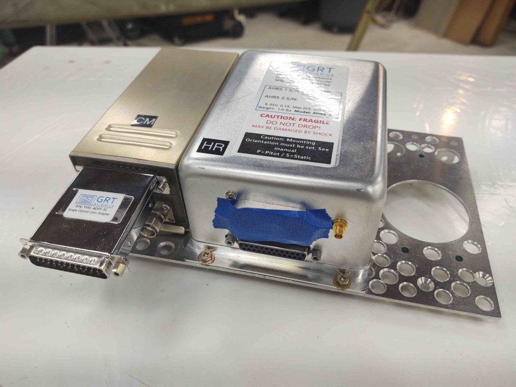
The top shelf bolt holes for the right angle bracket will match those of the TT22 mounting bracket (which is the same as the TY91 btw) so if I change out panel instrument(s) that don’t interfere with the TT22 I can simply remove the right angle bracket and mount the TT22 back on top of the shelf next to the AHRS box.
•••
22 August 2020 — Today I got to work on the last component to get mounted onto the Triparagon top shelf: the Trig TT22 transponder.
Here’s the bracket I cut late last year for mounting the Trig TT22 on the right side of the Triparagon top shelf. Again, due to clearance issues I can’t install it on the top of the shelf where I had originally designed it to go.
Here’s the initial bracket weight.
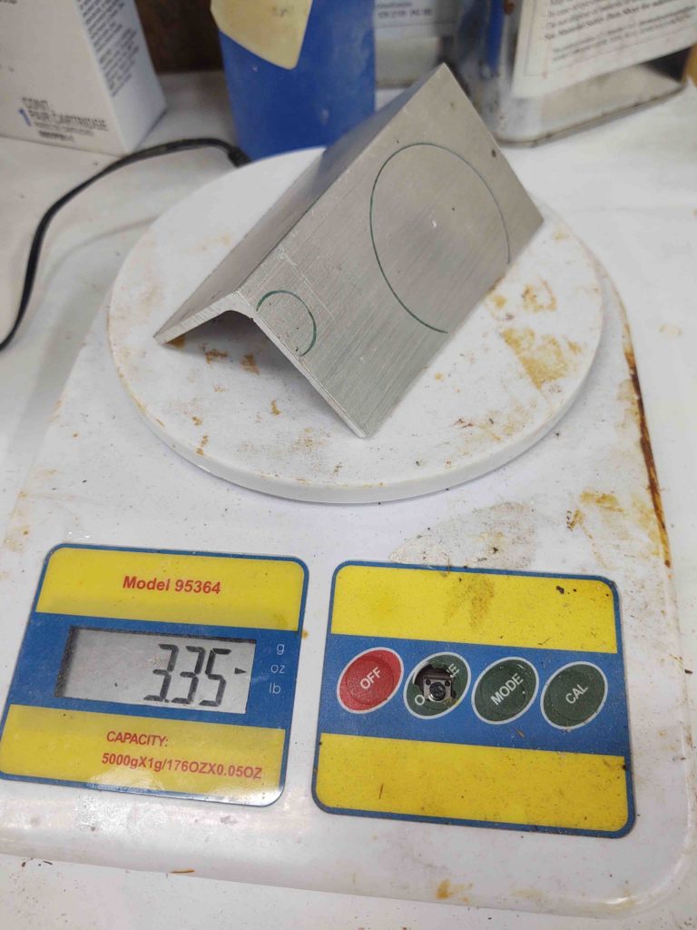
And after I drilled some lightening holes. I would say with all holes drilled it was fairly close to an ounce lighter in its mounted configuration.
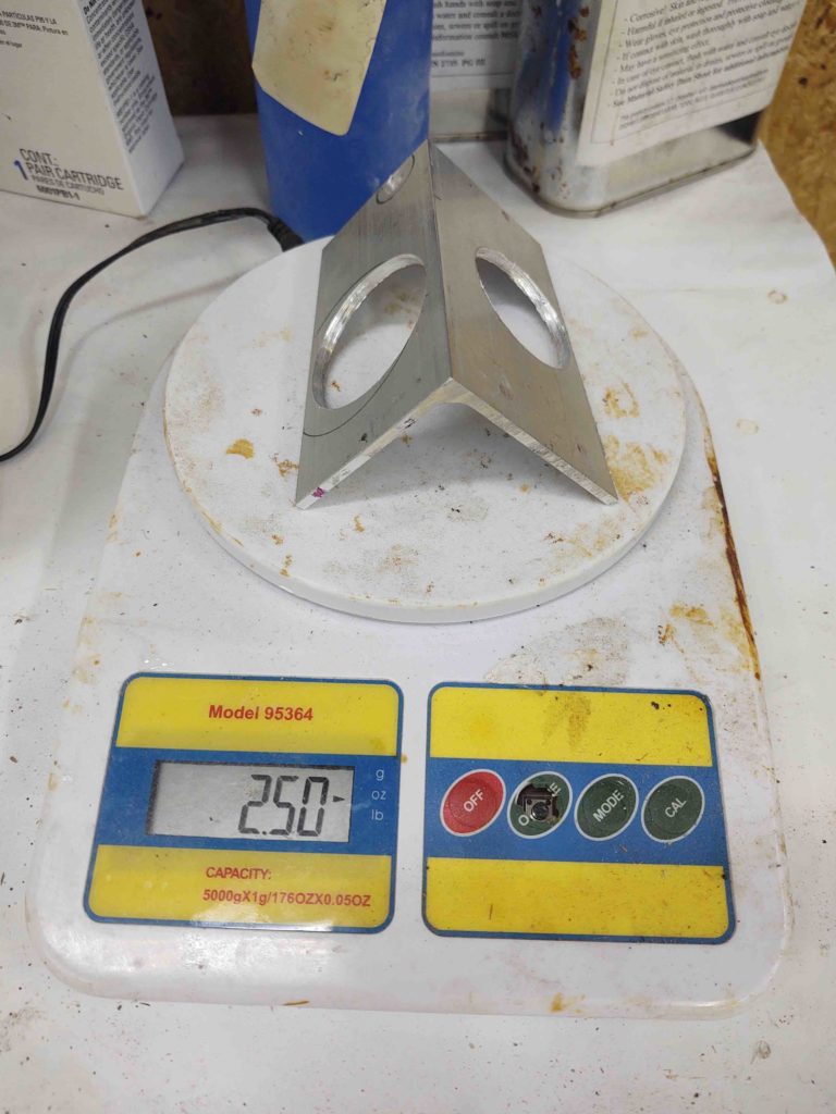
Here’s the bracket complete and mounted to the Triparagon top shelf. Note the actual Trig TT22 bracket on the side, and the actual bracket bolt hole pattern used on the top shelf… in case the opportunity allows for moving it back up top.
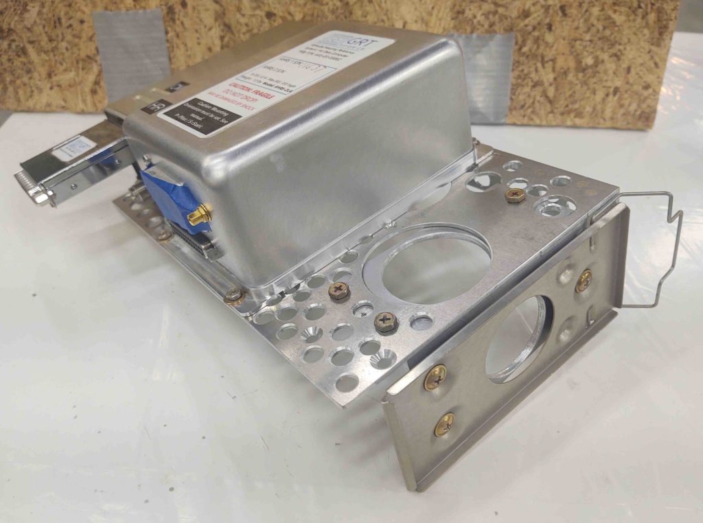
Here we have the underside, showing all the nuts and bolts, in their natural habitat.
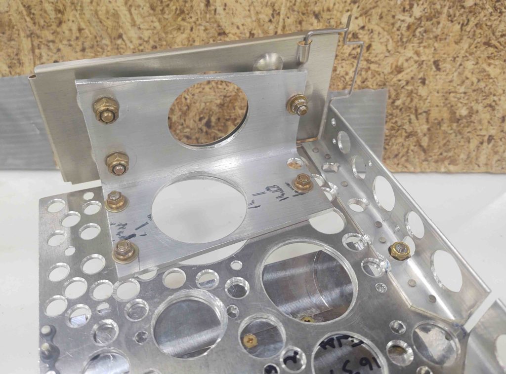
Finally a shot with the actual Trig TT22 unit installed.
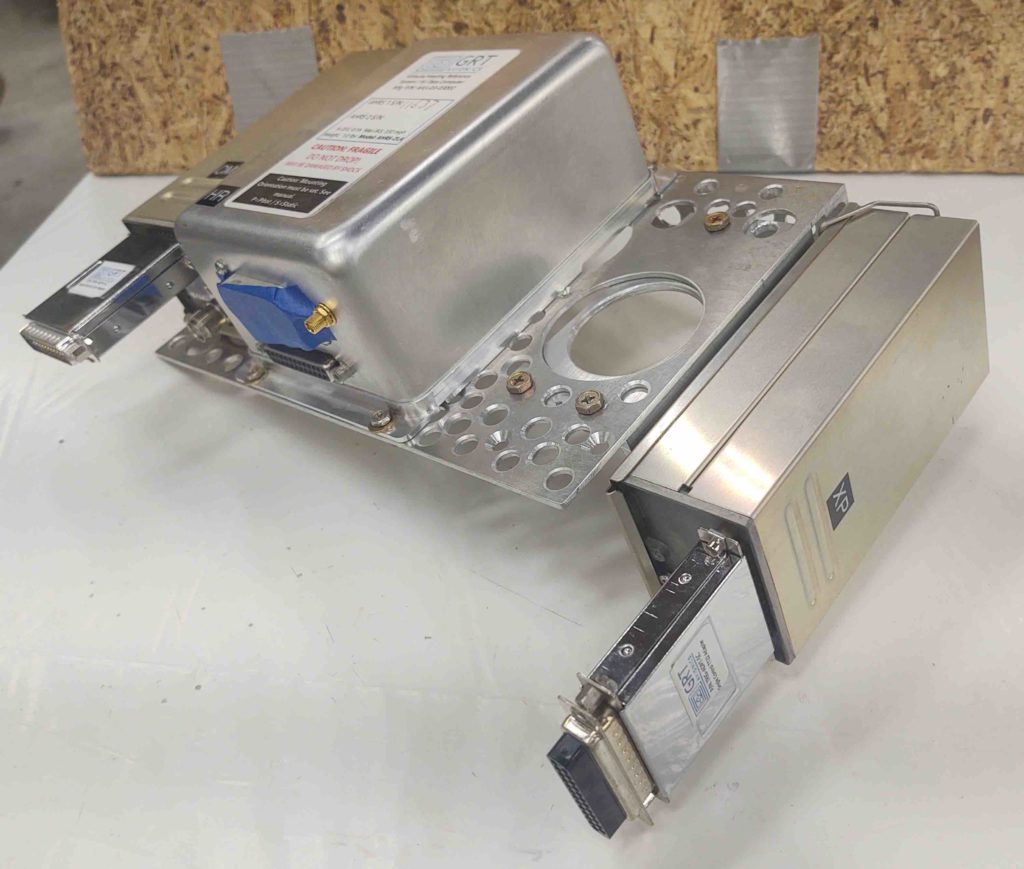
Another angle.
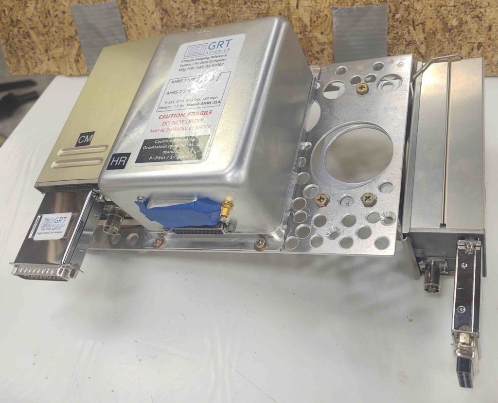
A final shot…
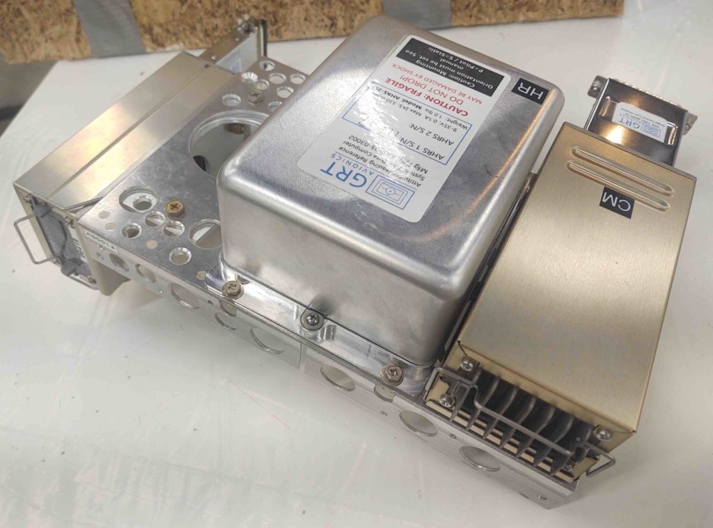
As I’ve noted previously, if any noise should arise in the headset or comms I’ll be prepared to move the transponder out to the end of the right strake. That being said, I have a number of canard buddies who are flying Trig TT22s mounting behind the panel with the antenna in the nose, with zero noise issues. So I figured I would try that route first.
•••
23 August 2020 — In my attempt at getting a “quick kill” in today with reassembling the Triparagon, I of course ran full face into some unintended consequences of my actions. The 2nd and 3rd order effect thing… or, as I titled this post: the butterfly effect. Yep, change one thing!
My issue that I failed to account for was static tubing access to my #1 airspeed switch. It was situated on the inside far right end of the front lip {red arrow, below} of the Triparagon top shelf, but I then covered that entire end with a makeshift cap called the Trig TT22 Transponder.
Thus began my 45 min journey of discovery of just how I was going to fix this predicament. Should I make a new bracket and move the transponder aft? (good thing I didn’t because space is tight with the panel-mounted GRT Mini-X, just aft of the transponder)… should I move it outboard? Or should I move Airspeed Switch #1?
Well, I chose the latter, it being the easiest of all options (some call it laziness, I call it efficiency… ha!).
Below shows where I ended up moving the airspeed switch to {yellow arrow}.
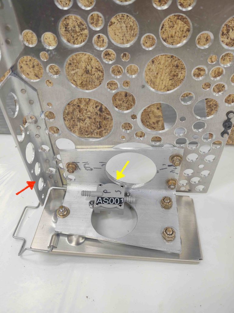
The one advantage of having the airspeed switches (there are 3) along the front edge of the Triparagon top shelf, is that they are accessible to fine tune the settings with a quick open of the aft nose/avionics cover.
Well, Airspeed Switch #1 will now not be AS accessible as the other two, but still not horrible. You see, I positioned it so that by simply popping the Trig TT22 transponder out of its bracket for a bit I can gain access to Airspeed Switch #1’s adjustment screw via the center lightening hole. Then pop the transponder back in place, close & secure the aft nose/avionics cover and it’s back to business.
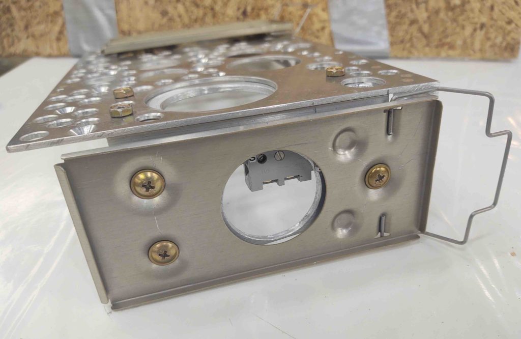
Here are airspeed switches #2 and #3 mounted on the front lip of the Triparagon top shelf.
Not shown is the reinstalled JBWilco Gear/Canopy Warning module and the warning buzzer.
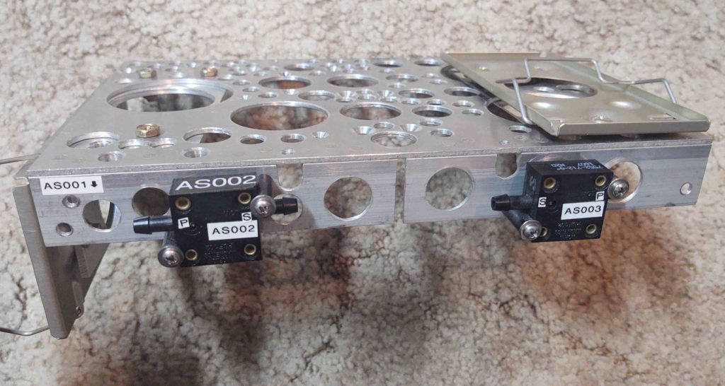
And although not a great pic, here is the Triparagon top shelf –with installed avionics– reattached to the rest of the assembly in the instrument panel mockup. At top center of the pic is the opening for the GRT HXr EFIS.
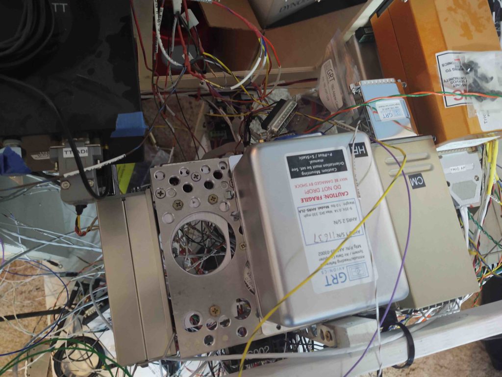
•••
26 August 2020 — Curiousity drove me to check out the placement of the RAM ball mount –for my iPad– install somewhere on the center panel strut. I had a decently long discussion with Marco on his configuration, so I used the info he gave me to get a head start.
First, I need to know where I’m going to mount the ball mount because it plays into panel design before I plasma cut it for real.
Also note that in this configuration I can see the fuel selector valve and a good bit of the nose gear window. It may look like the iPad is resting on my legs, but it is well off of them. Also note the visibility I have of all my main power avionics on the panel… none of them blocked.
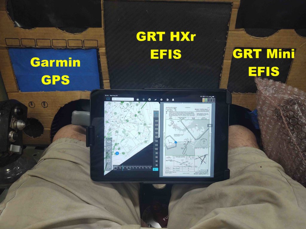
Part of the discussion that I had with Marco was the possibility that I may have to move some switches. Specifically my 2 big light switches. However, with this configuration I simply move my head forward a bit and I can see right over the iPad to both see and manipulate those light switches.
When I get a chance, I’ll update my instrument panel CAD file to reflect these changes.
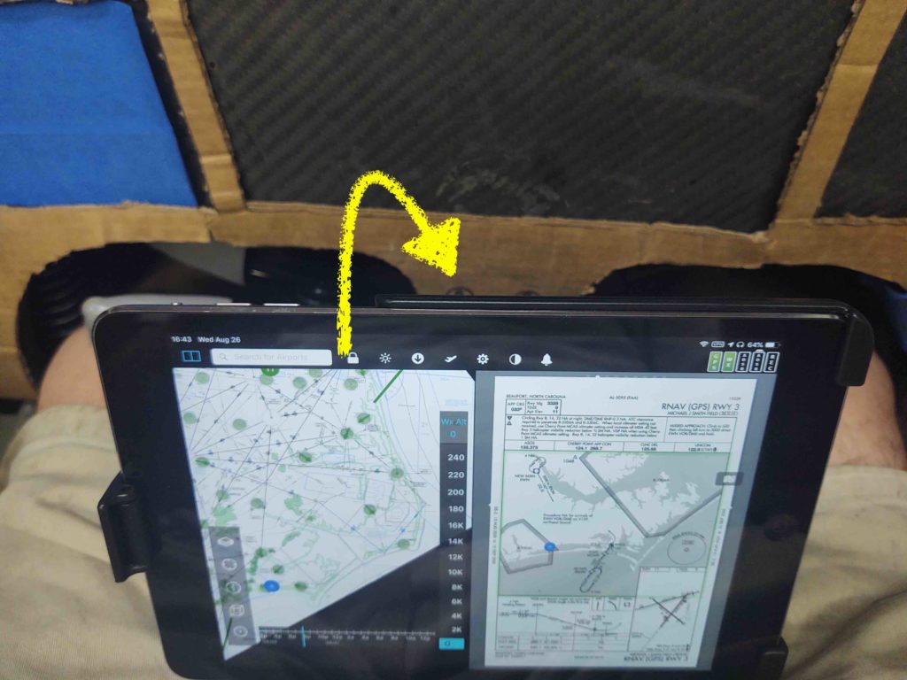
A curious point of note, at least for me, is that the iPad Mini actually fits completely inside my right armrest map/document pocket… pretty nifty!
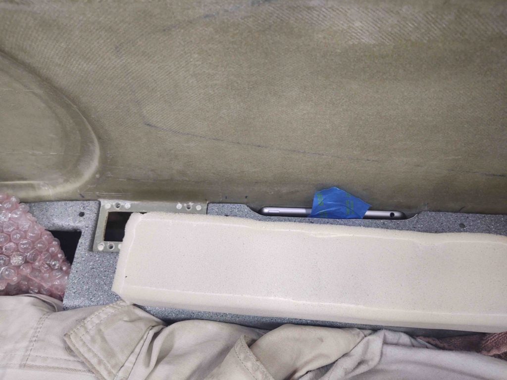
•••
27 August 2020 — I realized I didn’t show any of the “mechanics” of the panel RAM ball mount for the iPad cradle when I discussed it yesterday. Although the ball mount is covered in blue tape and clamps, you can see the actual ball at the bottom of the RAM arm. This gives you an idea where I’ll be mounting it on the center panel strut.
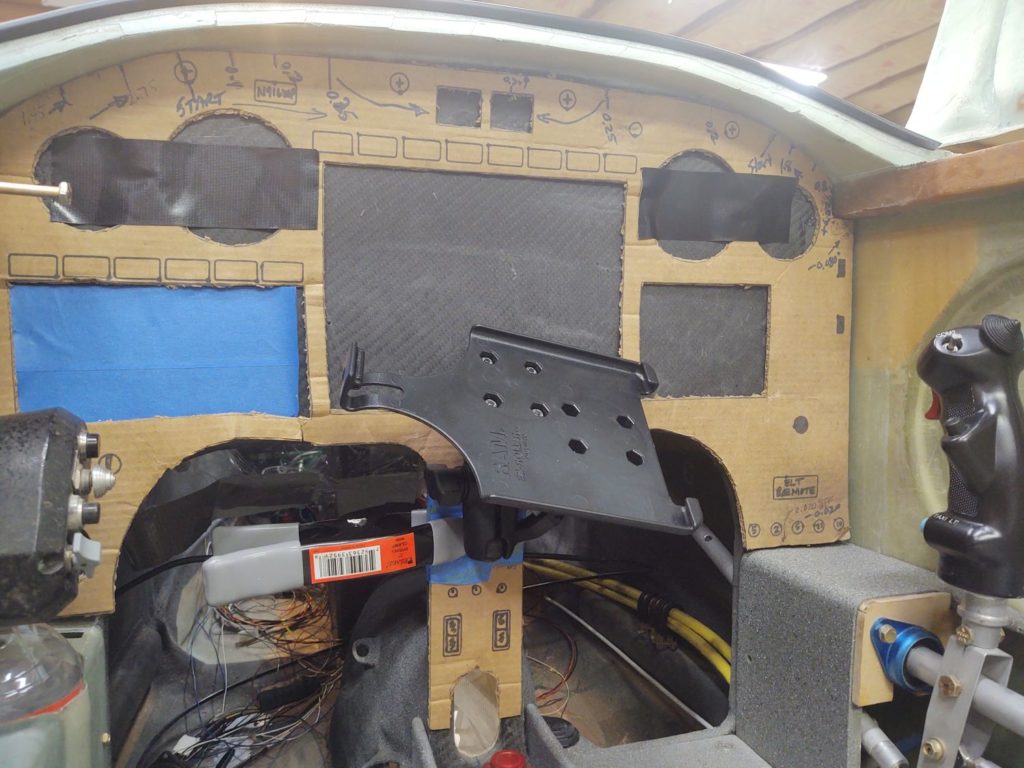
•••
3 September 2020 — Tonight I got back to work on the panel. I spent a good hour tracking down wires and making notes before I finally started re-populating the panel with the heavy hitters.
Here we have all the components back in place.
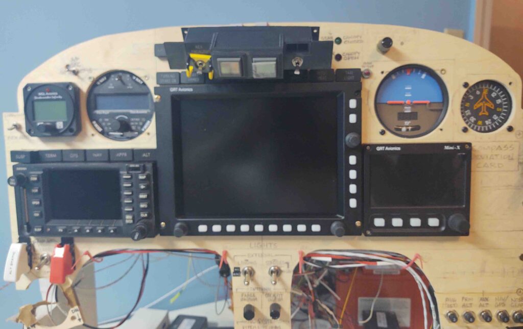
The first order of business was updating the EFIS & AHRS software on the GRT HXr and Mini-X EFISs. That went off without a hitch.
Although wired up, to stay sequential and minimize variables, I pulled the fuse on the Trig TY91 COM2 radio starting off. Note the empty right side of the HXr screen.
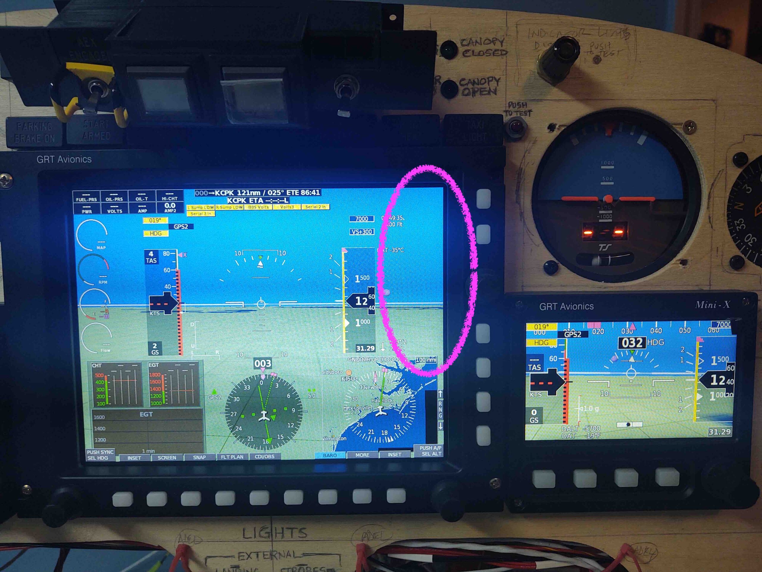
After the EFIS software was updated and units rebooted, I then replaced the fuse and added the Trig TY91 COM2 radio to the HXr EFIS configuration.
Now take a look at the HXr’s right side. First, note that this is appropriately labeled COM2as the Garmin GNS-480 is COM1.
The knob mid-right side of the HXr is used here to dial in freqs, with the primary/STBY freq SWAP soft button also showing.
The VOL soft button can be seen towards the bottom, and when pressed . . .
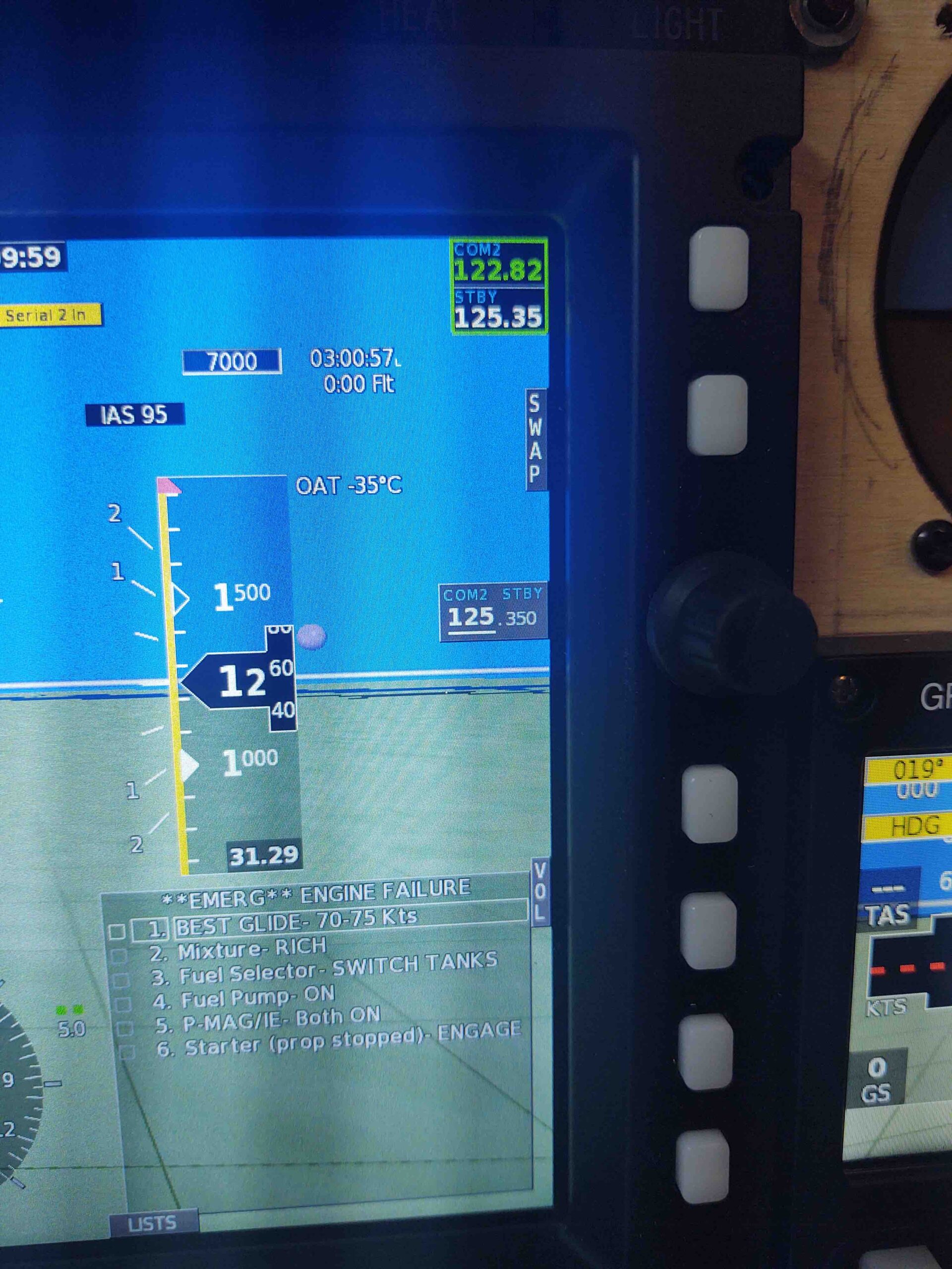
We get these side bar controls here. Note the side knob here controls the VOLUME, while towards the bottom the VOL soft button has changed to the FREQ soft button to get back to the freq entry if required.
EZ-PZ.
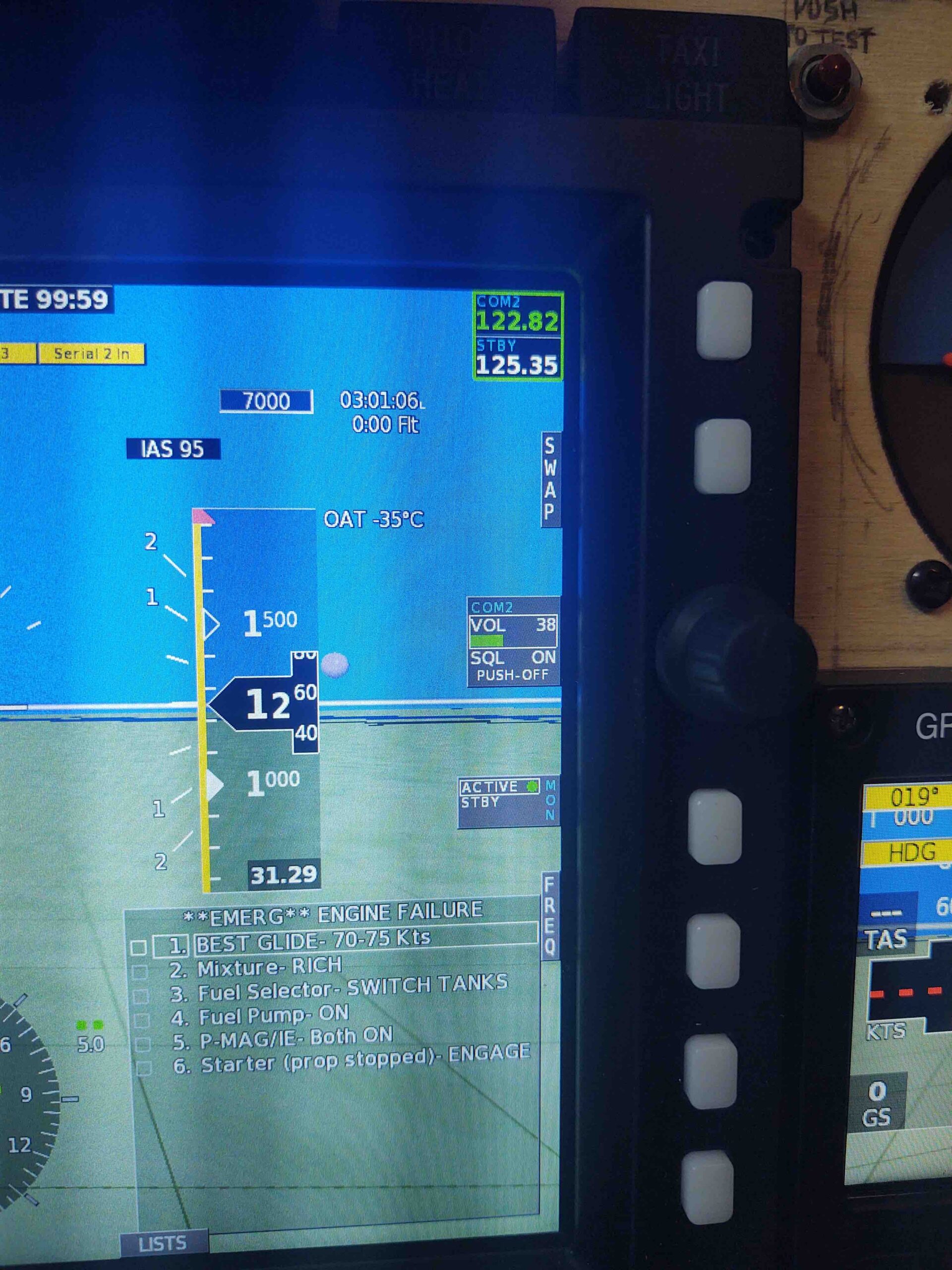
So the COM2 radio is installed… woohoo! Another component off the list.
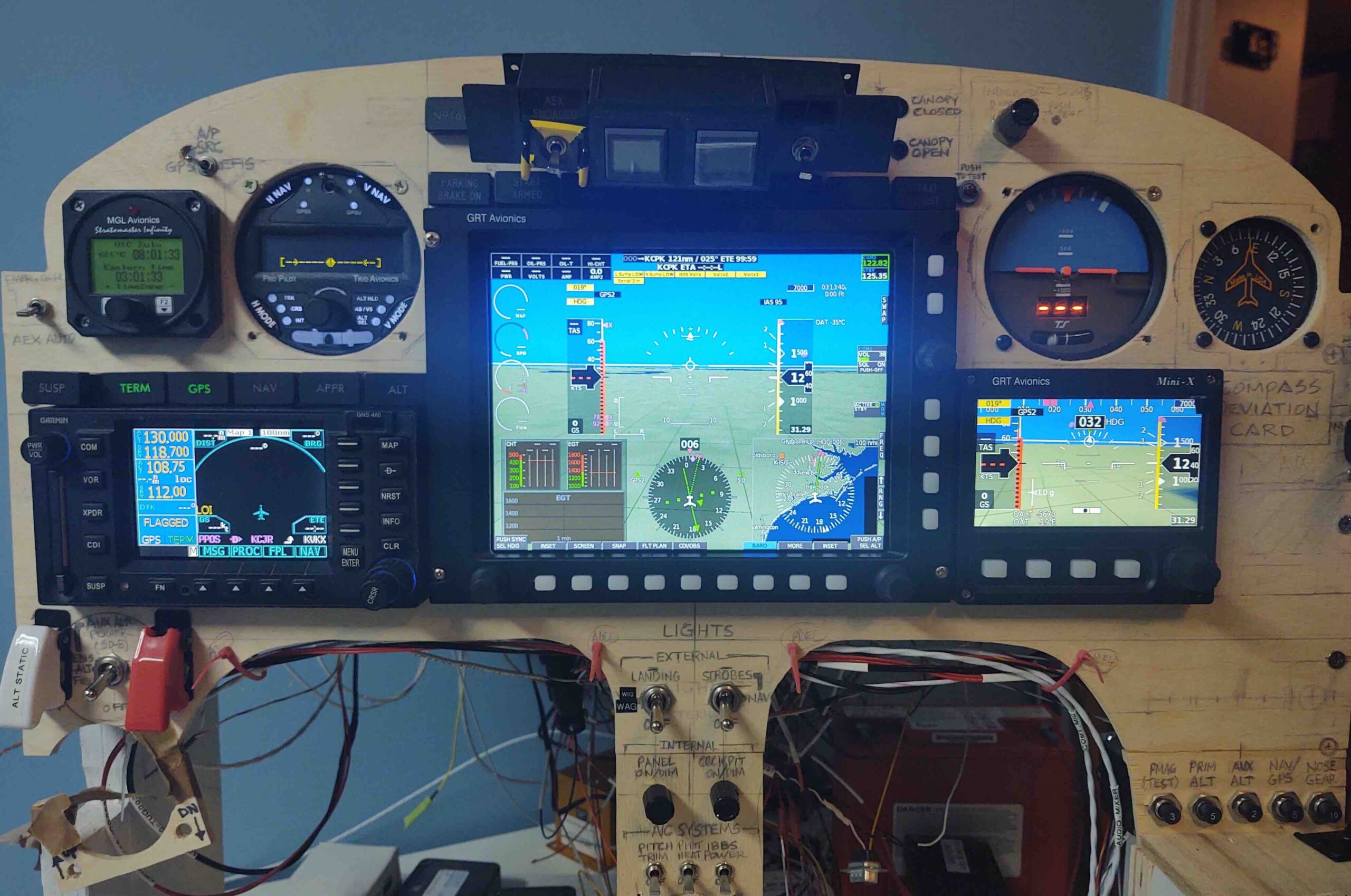
I played around with the EFIS screens for a bit, and have to say they make things SO EASY I just can’t wait to get this thing in the air and fly behind this panel… very cool!
•••