
Aft Nose/Avionics Top Deck Cover
29 May 2018 — I started off today taking a gazillion more measurements, and checking out other builders’ sites on their canopy positioning and inboard elevator root fairings. After getting my comfort level significantly higher on the whole of the plan working (at least on paper!) I got to work cutting out some 3/8″ PVC foam.
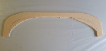
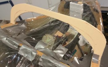
The first piece was for an intermediate bulkhead that I’m going to install just forward of the canard, which will look bow-shaped and will essentially serve more as both as a bit higher strength cap to the blue foam going in forward of it, and as a demarcation point for the avionics bay/nose cover going aft.
And yes, you read that correctly.
I will be incorporating a flip-up/removable cover for the canard and avionics area forward of the instrument panel and aft of F28. It will also overlap the panel going aft so that the canopy will physically lock it into place when closed (that of course is not the only securing method on the aft side).

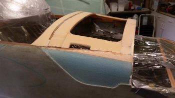
More on the avionics bay/nose cover below, for now here’s another view of the intermediate bulkhead that I’ll be securing into place before the nose foam is put in place.
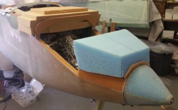
I also cut out a 1.8″ wide strip of the 3/8″ PVC foam that will be the front piece of what is roughly a picture frame looking foam rectangle that will be floxed and glassed in place for torsional strength of the upper forward fuselage between the panel and F28, and the upper longerons on each side. It will essentially be an interconnected “C” channel (just sandwiching foam in this configuration) around the entire edge of the avionics area, with all the glass locking the 4 sides (and corners) together.
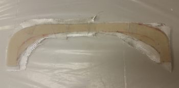
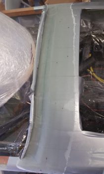
Another shot of the nose/avionics bay reinforcement piece, which is the first of 4 separate side pieces to be installed. This design will allow for a significant opening in the top for access to the avionics forward of the panel, which will all be enclosed by the removable cover that extends from the front edge of the canard to just aft of the instrument panel.
I’m aware that this design is deemed a bit controversially by some builders and Canardians, but I’ve studied a number of designs and am mitigating any induced weaknesses to the airframe structure by implementing it. In fact, I honestly think that my design will be significantly stronger that either the plans version or by simply having an avionics access hatch cut in the top of nose just forward of the canopy/instrument panel.
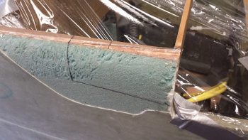
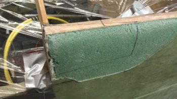
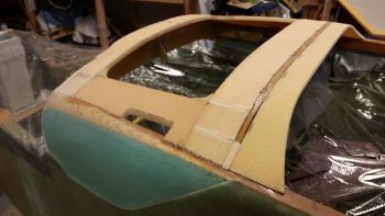
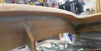
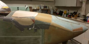
Part of my decision process today was to come to a final conclusion on exactly the design and configuration of the sides of the aft nose and avionics bay cover. My design uses some what of a split elevator fairing where the fairing itself is integral to the cover and then secures to a very robust bottom segment of the fairing via a screw up through the bottom securement tab into an embedded nutplate on the underside notched portion of the fairing.
Where the trailing edge of the elevator fairing intersects the fuselage sidewall and the inherent transition fillet on the underside of the fairing where the determinant dimensions for both the aft and bottom edges of the aft nose/avionics bay cover sides. After RE-reviewing a number of Berkut, Long-EZs and Dave Ronneberg designs with nose hatches, I settled on a simple angled transition from cover to fuselage at the instrument panel external fuselage area.
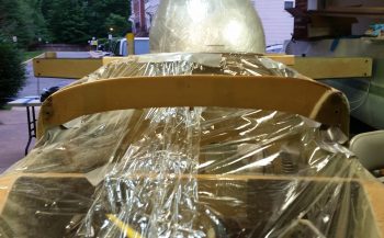
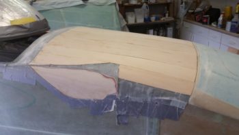
I double and triple checked all the possible associated variables and potential issues I could think of, and then I made the plunge. I made the final design version on the left side of the fuselage, then traced it to transfer it to the right side.
Which you see is completed here . . .
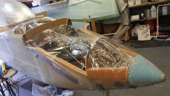
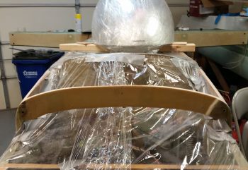
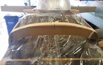
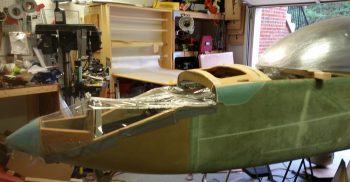
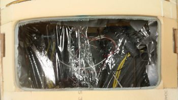
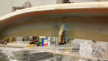
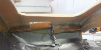
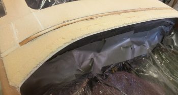
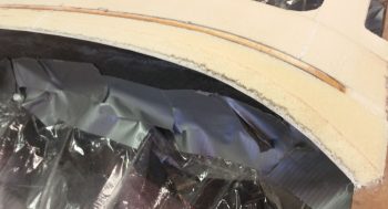
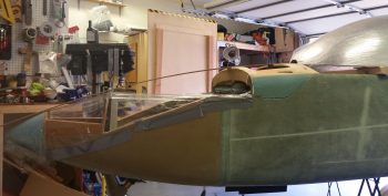
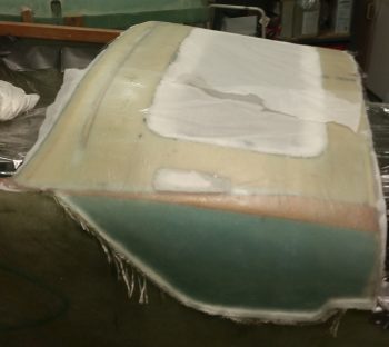
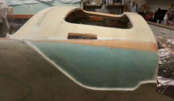
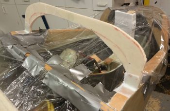
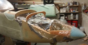
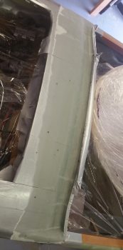
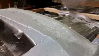
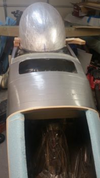
I then took my wide roll of packing plastic and wrapped up the nose from tip to instrument panel to protect the innards from errant fiberglass, foam and other nasties.
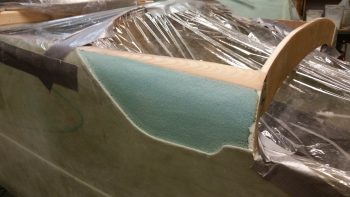
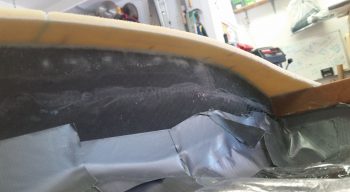
I then loaded a fresh blade on my Fein saw and got to work on my respective fuselage sidewall surgeries. My goal was to cut just enough in depth to cut through the glass and not get into the foam underneath.
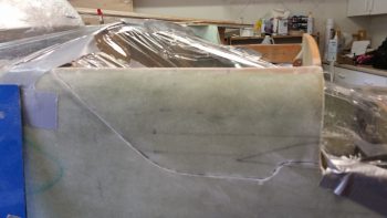
If I had any doubts as to how secure my glassing was on the fuselage, this endeavor laid that to rest. It took a good 20 minutes minimum on each side to get the glass pried off while being careful not to damage the foam underneath.
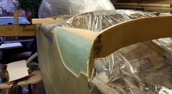
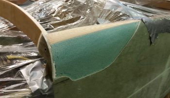
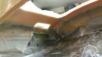
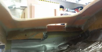
The action here was actually a 2-part task in that not only did it expose the areas on the upper/forward fuselage sides that will allow me to create depressions for the aft nose/avionics bay cover, but also to correct my previous non-shaping of the front “corners” of the fuselage that should have been significantly rounded over before the fuselage exterior was skinned.
In the summer of 2012 I glassed the exterior of the fuselage without having caught the requirement to round the very front of the longeron and nose sidewall foam, as you see that I’ve just done on the right side (left pic below) vs the way I had it (right pic below). Yes, I was living in blissful ignorance until Marco went to glass his fuselage, at which point he queried me about it. I gave him my incredibly well thought out reply of, “Huh?! What are you talking about?!” Followed a bit later by, “Ah, <enter appropriate expletive here!>” To see a great explanation of this, check out Marco’s blog.
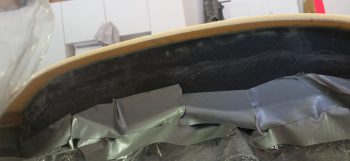
As for the aft nose/avionics bay cover, I will be laying up glass back onto this exposed foam area with overlap back onto both the existing fuselage sidewall glass and onto the new aft nose/avionics bay front reinforcement structure (“picture frame”) that will be in place between the panel and F28, and the longerons on each side. This will serve not only to replace the structural element of the previously removed sidewall glass, but tie the fuselage sides to each other via the reinforcement structure.
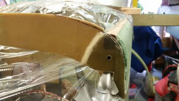
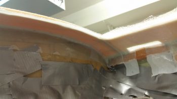
So here’s my shaping the forward top longeron intersections with F28, with the right side (left side of pic) nearly finished and the left side still untouched.
I then finished the forward top longeron shaping to about 90%. I still have to do a tad bit more dialing-in so that both sides match in shape, but it was late, I was tired of sanding and sanding with a hard board is amazingly loud, so I wanted to take it easy on my neighbors and finish the final 10 minutes worth of sanding tomorrow. I also need to finalize the depth of my sidewall depressions in the exposed foam.
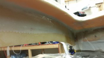
Here’s another shot of my shaping the forward top longeron intersections with F28, with both sides shaped this time around.
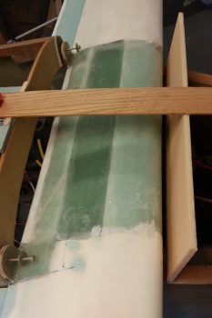
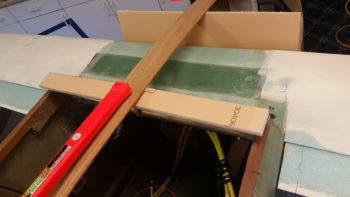
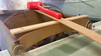
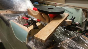
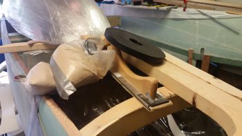
Yes, I should have taken a picture of my shaping and prepping of the aft nose/avionics bay front reinforcement piece before I floxed/micro’d/5-min glued it in place. This pile ‘O stuff is simply to keep the various parts of it weighted down <correctly> since the aft end of this piece is ever so slightly raised to match the downward angle from the panel to the F28 bulkhead.
This contraption (aka “convoluted pile of crap”) right here is exactly why I decided to set the 4 sides of this internal reinforcement frame in individually, since the installation of each side/edge has it’s own unique requirements and challenges. Once all the pieces are floxed/micro’d in place, I’ll do a final sanding & shaping of the new “one-piece” structure and glass it in place as one unit.
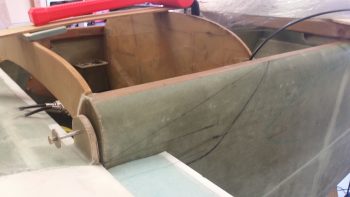
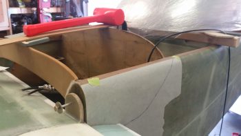
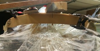
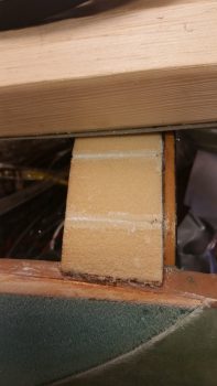
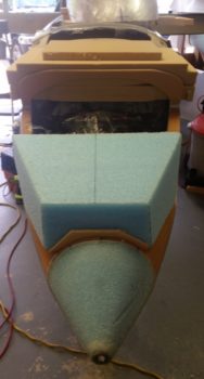
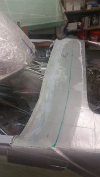
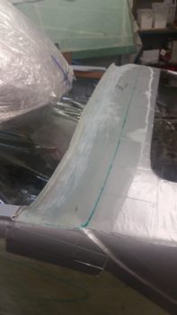
Here’s a straight on view of the aft nose/avionics bay front reinforcement piece. As you can see, the center section is situated and mounted on the top edge of F28, where the outer 30% on each side is then even with the top edge of F28. This gives me just a tad bit more height in the center area of F28 for a good nose angle flow from the panel to nose tip as it traverses F28.
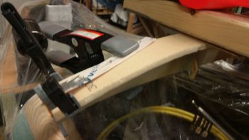
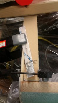
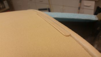
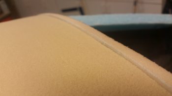
And a couple more shots of the aft nose/avionics bay front reinforcement piece on the left side. The transition from the piece being on top of F28 to simply adjacent F28 is underneath the taped popsicle stick securing the bonded mating surfaces, but you can make out the foam piece floxed in place at the F28-longeron corner junction.
•••
30 May 2018 — I started off today by clearing off the big, convoluted pile ‘o stuff off the floxed/micro’d in forward avionics bay cover reinforcement piece. I was quite pleased with how it came out.
A couple of reminders on this thing. First, this piece is the first of 4 pieces to get installed. Just think cardinal headings and you get the gist. Next up will be the aft piece that attaches to the top front edge of the instrument panel.
Next, when all 4 pieces are in place, interconnected, and glassed, this area will provide reinforcement from one fuselage side to the other and replaces the top foam avionics deck/aft nose cover that the plans says to glass in place just forward of the instrument panel.
Lastly, this forward piece specifically also serves to increase the height of F28 about 0.4″ to allow for a better flow of the top nose profile and removes a flat spot that was apparent in the nose contour.
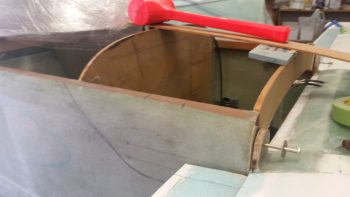
Here’s a view from the aft side of the first of 4 pieces to go in around the perimeter of the avionics bay.
Before I went any further, I took a good half hour to ensure that the right side top forward longeron & F28 were trimmed, sanded and shaped to match the left side. As per my usual response, they’re not perfectly matched, but pretty darn close.
Here I used a Sharpie as a sanding guide coat to “flatten” the top side on the right to better match the left side.
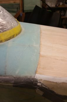
Pardon the bright sun in the background, but here’s a decent depiction of the top nose section “corner” curves now. Much, much better than they were before and I’m very pleased with how they turned out.
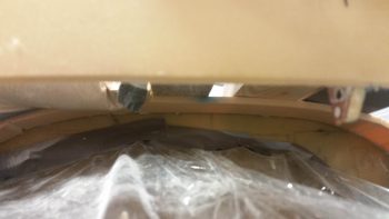
I then cut, shaped and floxed in place the 3/8″ thick x 2.2″ wide PVC foam piece to the front top edge of the instrument panel. Since this too has the apparent requisite pile ‘o crap on top of it to hold it all down in place, I grabbed a shot from underneath. It’s the first foam structure visible just above the gray tape line… and a bit more visible on the right side of the pic.
To get the foam to behave, especially on the outboard edge curves, I drilled a series of small holes along the top edge of the instrument panel and used nails to keep the foam aligned properly.
Here’s a view of the right side reinforcement foam piece. As you can see I cut relief lines in the foam, although this piece actually snapped off entirely at the top relief line as I was setting it in place. No worries of course since I just micro’d it in place.
And here’s the aft foam reinforcement piece, or rather the pile ‘o crap securing the aft foam reinforcement piece. This is #2 of 4 pieces with the side pieces coming up next.
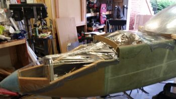
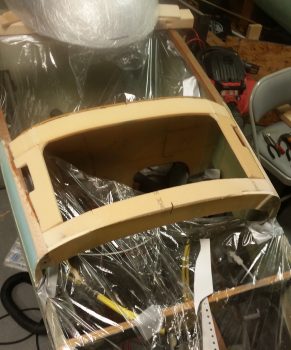
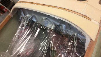
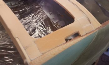
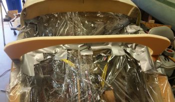
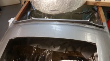
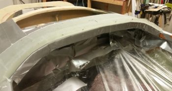
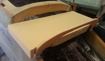
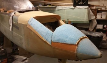
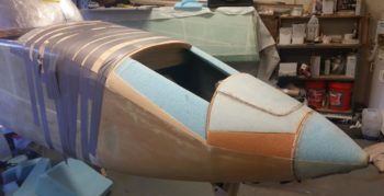
<Fingers snapping> Voila! And here are the side pieces almost completely in place. If you look closely you may be able to see that the front inboard corners are sticking up about a foam’s width high, due to the shape and curvature of the nose. I floxed/micro’d both side pieces in at the aft side and about 2/3rds of the way down the aft outboard edge (to the longeron) and will let them completely cure before making the minor twist at the front edge to secure the side piece to the front cross foam piece’s aft edge.
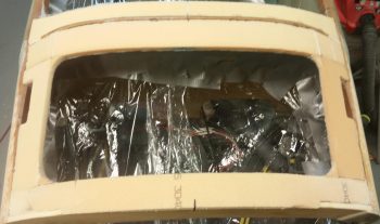
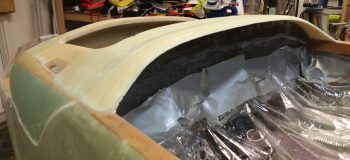
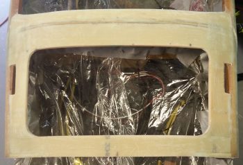
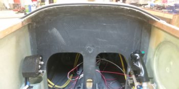
This is a very good shot showing the access I’ll have to the avionics through this hole created by the 4 foam edge pieces. Yes, this access hole is significantly larger than what many builders have done by creating an access hatch in this area of the nose. I honestly feel (IMO of course) that once the glass is in place that there will no loss of structural integrity in this area, especially when the cover is secured in place.
Here you can see –about 5 hours later– I’ve micro’d (foam) and floxed (foam to longeron) the front of the side foam piece to the front cross foam piece’s aft edge using a nail to align and secure the 2 pieces. The clamped on vise grip is to induce a slight twist to get the outboard edge to pivot up a hair (about 0.050″) –using the nail as the fulcrum– to better align the side foam’s outboard edge with the longeron, elevation-wise.
The slot in the side foam piece (on both sides) is for a length of structural hinge that will be attached to the underside of the aft nose/avionics bay cover on a vertical tab and will align and attach to an interlocking length of structural hinge that will be floxed/glassed onto the underside of the longeron. The hinge pin will be modified with basically a set screw on the aft end that will be secured into a threaded point on the instrument panel, one in each upper corner of the panel. When the cover is to be opened, unscrewing the hinge pins and sliding them aft will complete the hinge pin removal step.
[There will be a circlip on the hinge pin assembly that will A) not let the hinge pin be removed (or lost) from the panel without specific effort, and B) not let the hinge pin exit the aft-most tab on the longeron mounted hinge assembly, thus ensuring the hinge pin assembly is always ‘locked & loaded’ alignment-wise and ready for pain free insertion into the aft nose/avionics bay cover’s hinge assembly once the cover is closed and the upper hinge bracket drops into alignment with the lower hinge bracket].
After a LOT of assessing, measuring, research, assessing, cardboard mockups, more research, more measuring, pondering, etc. I finally came very close to the final configuration on the plan for the interface of the nose/avionics bay substructure, the aft nose/avionics bay cover, and the front canopy skirt.
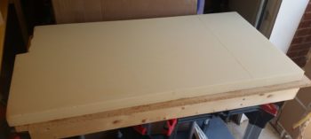
With my researched and tested plan in hand, I got to cutting some foam. First up was the 1/4″ thick PVC foam that will make up the BOTTOM, permanent glare shield substructure. I was originally going to just use a number of plies of glass for the glare shield sub structure, but I needed a bit of depth from the top of the instrument panel to create a drop down edge going aft for the front canopy skirt to seat onto/into.
The 1/4″ thick foam is a compromise for getting some depth/thickness for the glare shield and also the max thickness of any intrusion of the instrument panel’s perimeter in regards to both the physical clearance of panel components and visibility of the panel.
You’ll see later on that the front edge of this 1/4″ glare shield sub structure will get beveled at an angle going forward, and will support the aft nose/avionics bay cover that will follow that beveled edge and create a lip going aft of this foam (and glassed) glare shield sub structure to sit under and “interlock” with the bottom edge of front canopy skirt.
Also, as a point of note, the permanent glare shield substructure will be where the strip of blue LED cockpit lights are permanently attached to… so that the lights are tucked up and out of the way..
The front-to-aft depth along the majority of the foam glare shield substructure is 1.3″, while the flare at each end is 2.4″ thick. My estimation of total foam width (accounting for the down curve and angle at each end) during foam cutting was about a half inch too long, and since each outboard end was specific in design and the middle area was static in its 1.3″ width, I had to cut about a 1/2″ out of the middle and install the glare shield foam as 2 separate pieces. Since I have no “backside” real estate for nails on this go around, I tried to hand jam it with flox and some 5 min glue dabs along the length. Well, the 5-min glue sorely disappointed and I ended up scrambling to clamp it and weigh the left half 1/4″ foam glare shied substructure piece in place.
It was late so I’ll let the left half cure before tackling the right half tomorrow.
Creating a modification such as the aft nose/avionics bay cover is always slow and time consuming, not to mention quite maddening at times, but I really feel that having to take about 5 minutes to deal with hardware removal and then being able to rotate a cover forward to expose and provide access to the avionics bay and F28 forward/canard mounted items such as GPS antennas, airspeed switches’ adjustment screws, etc. . . . all pretty much on the fly and on demand will be quite worth this mod.
Moreover, it will clean up the external flow and look of the nose since I will have only one large hatch and then only one other break in the nose at the forward edge of the cover, just forward of the canard. In addition, it allowed me to do the top canard tab long bolt attachment mod which although clearly not a mandatory mod, is definitely my preference.
•••
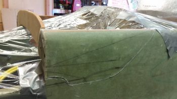
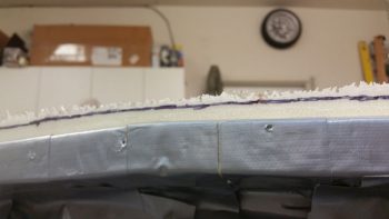
31 May 2018 — Here’s a shot of my starting point today with all the avionics bay foam reinforcement pieces in place.
Clearly I was missing the right side glare shield 1/4″ foam substructure. When I claimed yesterday that I had no backside clearance for nails, it dawned on me this morning to not let the nail holes go to waist and use toothpick tips as wooden spikes in the same manner as we did when we build the canard!
I then floxed/micro’d the right side glare shield 1/4″ foam substructure in place. I have to say my wood “spikes” worked a treat!

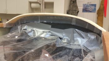
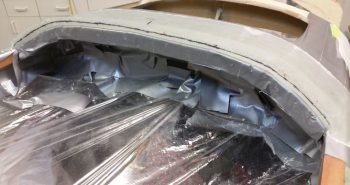
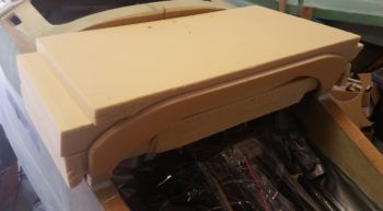
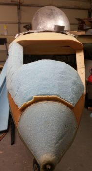
So, here’s a shot of all the aft nose foam in place. From here on out any foam that is added will be a permanent part of the external nose structure (as versus the cover).
Here are a another few shots of the avionics bay reinforcement foam structure and the foam glare shield substructure.

I took a wider angle shot to show how the progression of the nose is coming along.
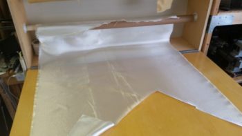
I then spent nearly an hour cutting glass. I then prepregged and wet out 2-ply BID tapes for the underside layups of the avionics bay reinforcement foam structure.
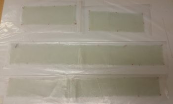
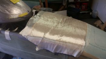
Here you can see the over (or under!) hanging glass of the avionics bay reinforcement foam structure layups. I was on the fence about peel plying the layups, but it is so hot and humid that the glass seriously wasn’t overly interested in sticking to the wet micro’d foam! Using peel ply was magic and kept the glass wrangled and right in place!
Here’s a smattering of pics showing the BID layups on the underside avionics bay reinforcement foam structure.
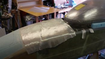
After the underside avionics bay foam reinforcement structure was glassed and peel plied, I then set my sights on the 2-ply BID layup for the underside of the foam glare shield sub structure. Again, I most definitely peel plied it as well!
Here’s another lower angle shot of the 2-ply BID layup on the underside of the foam glare shield sub structure.
My last official act of the evening was to razor trim the avionics bay reinforcement foam underside layup glass edges.
•••
1 June 2018 — I started off today by going down to the shop to finalize the cleanup of the Avionics top deck underside layups. Again, these layups won’t win any beauty awards, but they are functional and strong, so I’m going to call that a win…

I then did the same for the underside layup on the glare shield substructure.
I marked a bevel line 0.6″ forward of the glare shield aft edge, but before I did anything with the glare shield I sanded down the high points on the Avionics top deck reinforcement foam in prep for glassing.

Here we have the bevel line that I marked on the top side of the glare shield 0.6″ forward of the edge.
I then beveled the edge on the glare shield substructure edge and then removed the foam at the edge creating a small “trench” to expose the glass underneath. I then sanded the glass in prep for adding flox in the “trench” to facilitate a better glass-to-glass type bond.
Here’s a better view of the beveled edge & “trench” on the glare shield substructure.
I also created a narrow “trench” on the edge of each fuselage sidewall depression to also increase the strength of the bond at the intersecting glass.
With my avionics top deck foam structure in place, I did a quick final check of my nose profile. I like it!
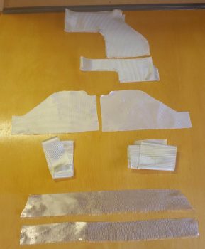
I then spent a bit of time both determining/finalizing my layup schedule and cutting the glass. The layup schedule sequence starts from the bottom of the pic below with a ply of UNI (lower left) that starts on the front side of the fuselage sidewall depression and travels across the front avionics top deck foam reinforcement and then stops at the opposite fuselage sidewall depression. Then another wider ply of UNI (lower right) was laid up at the aft end of the avionics top deck, essentially across the aft foam reinforcement piece and the instrument panel top edge. It too is laid up from one side of the fuselage sidewall depression to the other.
The next ply –the first full ply of BID– consists of the 4 middle pieces of glass, with the visible fuselage depression-shaped pieces going in and then essentially “cross strap” pieces going across the top. The seam for these pieces is parallel to the aircraft centerline.
Finally, the last (top) ply of BID is the 2 pieces at the top in the pic below. The bottom of the 2 pieces gets laid up on the front side of the avionics top deck, with the top piece getting laid up last, overlapping the front piece by a good inch. The seam for these pieces is perpendicular to the aircraft centerline.
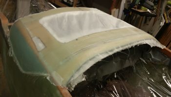
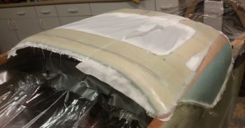
And here’s the Avionics top deck foam reinforcement structure glassed and peel plied.
 I then ran out and grabbed dinner, beers and a movie with my buddy Rob. When I returned and checked the layup it was ripe for final steps, so I pulled the peel ply and razor trimmed all the edges.
Tomorrow I’ll edge sand all the rough edges, but I of course got the lion’s share of glass trimmed off the layup tonight.
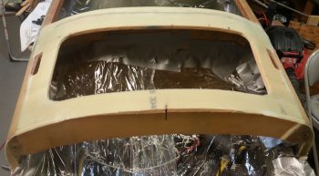
Here’s a couple shots that include the fuselage depressions for the avionics top deck nose cover.

I have to say that I was very happy with how the layup turned out.
•••
2 June 2018 — Today I started off with a good sanding of all the edges and surfaces of the Avionics top deck…
which I guess is now a hatch as well.
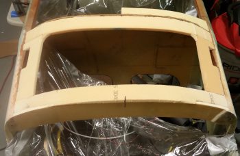
I then got to work estimating the sides/corners and middle open area of the nose intermediate bulkhead. I started to cut the middle open area with the inside edges positioned much farther out before I reiterated to myself that there is a significant transition from the aft squarish-shaped nose cross-section to a much more round cross-section the further forward the nose goes. So I added some mass back in since most likely it is the outer “corners” that will get shaved off during the nose build process.
I then mocked up the intermediate bulkhead. Again, this intermediate bulkhead is the demarcation line in that everything forward of it is “standard” nose and everything aft of it lies under the aft nose/avionics top deck cover.
I then glassed the aft side of the intermediate bulkhead with 1 ply of BID and peel plied. If you’re wondering about the front side of the intermediate bulkhead, it stays in raw foam form since it will combine with other raw foam to make up the forward nose walls.
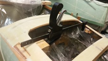
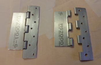
I then got to work on some of the hardware that will be used to secure the cover to the aircraft, as you see here with these hinge assemblies. The 3-ring hinge assemblies will be attached to near-vertical tabs that extend down on the underside of the cover and then extend through the Avionics top deck via the 2 slots that look like hand holds on each side (see both top pics above).
The 4-ring hinge assemblies will be floxed & glassed in horizontally to the underside of the longerons, just aft of the longeron doublers and extensions (directly underneath the slots mentioned above). These obviously are the aircraft side of the hinge lock pin equation.
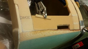
Also mounted on the fuselage-side are the two strike plates on the left of the pic below. Each of these will be mounted to the inboard “face” of their respective longeron and will be what the upper (cover) hinge lock assembly hits first, at a very slight angle, which then pushes the cover’s hinge lock assembly inboard a bit until it clears the strike plate and then snaps into place –interlocking– in the lower fuselage side hinge lock assembly. The hinge pin will then be pushed forward from the instrument panel side to lock the upper and lower hinge lock assemblies together.
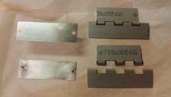
Besides wet flox, the strike plates will be held in place by a countersunk aluminum rivet on each side, used as pins inserted into small diameter holes drilled into the longerons. The strike plates are made up of 0.040″ thick 2024T3 aluminum and measure 1″ x 3″.
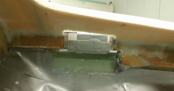
I then floxed the hinge strike plates to their respective inboard longerons and spread clamped them in place.
Here’s a closer view of the left strike plate floxed and clamped in place.
After pulling the peel ply and trimming up the layup on the intermediate bulkhead, I micro’d and glassed it to the nose sides using 2-ply BID tapes on both the front and aft corners.
Here’s another shot of the intermediate bulkhead (sorry for my POS camera!).
And here’s a wider angle shot showing the clamp holding the floxed strike plates to the longerons and the intermediate bulkhead glassed in place.
I had planned on doing a few more layups, but my better judgment actually won out tonight and said to break a littler earlier than I normally would. I’d be working on the avionics top deck area and I wouldn’t want to inadvertently hit the intermediate bulkhead while it’s curing. I have it spiked in place with toothpicks, and the measurement has stayed locked on like a laser sight, so I’m not going to mess around with a good thing.
•••
3 June 2018 — I got into the shop and started off by narrowing the fuselage-side mounted lower hinge lock assemblies for the avionics top deck cover. After narrowing them, I drilled thru-holes for the flox to grip the hinge plates better.
I installed the hinge pin (for the right side I used finishing nails) and then taped up both the inside and outside corner, with the upper hinge lock assembly in the vertical position… 90° to the hinge locking plate that was getting floxed into place.
I then floxed in the lower hinge locking plate on each side. After each plate was set in place with flox, I then made up a 4-ply BID prepregged layup for each side measuring 1.4″ x 4″ to secure the lower plate in place on the underside and overlapping onto the fuselage sidewall. Before laying up the glass I added a flox fillet in corner at the intersection of the underside hinge plate and the fuselage sidewall. I then peel plied the bottom edge with a 1″ strip of peel ply.
A few hours later I pulled the peel ply and removed the upper hinge lock assembly. Kind of a funny oops was that on the left side I can’t get the hinge pin out since there’s no clearance! No worries since I’ll need to drill a hinge pin hole through the instrument panel anyway. I would like to point out that the hinge pin is at the exact spot I was planning for it to exit through the panel.
Here’s the upper hinge lock assembly back in place, in a down position to be able to see it better. To be clear, no “hinge” swivel action will be taking place with these hinges, they are simply locking devices to keep the avionics top deck cover secured in place.
This is actually a better representation of the upper hinge lock assembly since it will be pointed upwards in final configuration. Once the cover is completed and in place, this hinge lock assembly will be riveted to a tab hanging down from the underside of the cover.
I then spent another good half hour assessing and pondering exactly what methodology I was going to use to create the top cover. Throughout the past number of years as I have planned to have this aft nose/avionics top deck cover, I have considered the standard adding-then-shaping-foam method. Of course that called into question on exactly what type of foam to use? Blue, urethane, or pour foam? Or even a thin layer of PVC foam?
I also considered a straight glassing method, but then while it is simpler, it doesn’t allow for contour shaping which is something that really needs to happen.
Then, as I was moving stuff around in the shop this past week, I ran across some 1/16″ thick x 4″ wide strips of Balsa wood . . . hmmm? Could I? . . . interesting. Well, after playing around with the strips of Balsa wood, the mystery was finally revealed in just how to get the aft nose cover constructed: Balsa wood! Yep, with the avionics top deck sub-structure already at the proper angle, and my having sanded both sides to match in elevation, the Balsa wood strips will easily hold their shape spanning the avionics access hole and be flexible enough to contour to the surface of the avionics top deck. That will give me about 80% of the cover’s surface with just the area on each side forward of F28 up to the intermediate nose bulkhead to contend with… which I’ll simple shape foam in the more traditional method at these points.
With plan in hand, I worked it through a number of times in my noggin until I flushed out the various kinks and got a good handle on the sequencing.
As a point of note, the aft nose/avionics top deck cover really isn’t a huge cover and is just a bit over 2′ long from front to back. And about 2′ wide of course from side-to-side. The cover will have a minimum of 10 attachment points, but most likely 12 when completed.
•••
4 June 2018 — Today I set my sights on glassing the aft end of the avionics top deck cover which is technically the actual glare shield.
I started by adding a urethane foam shelf that stuck out from under the glare shield sub-structure by 0.9″.
I then added a taped foam wall on the aft side that will create a lip on the aft edge of the glassed glare shield once it cures. This lip will both interface with the canopy front skirt as an ad hoc interlock and will also serve as a drip guard/block to keep any incoming moisture diverted to the outboard edges of the canopy skirt.
I laid up 3 plies of BID in what will be the bottom (interior) surface of the aft nose/avionics top deck cover.
My layup for these 3 plies of BID had the first ply going on at 4.5″ wide, with the next ply at 3.5″ wide, and the final ply at 2.5″ wide. My primary focus was on the aft “trough” side of the layup to ensure that all 3 plies were laid up well to create a strong glare shield, especially since it will have a structure consisting of nothing more than cantilevered glass.
Again, to reiterate, these 3 plies are the bottom/inside surface of the very aft edge of the avionics top deck cover, so more plies will be added to these as the top cover is constructed.
To facilitated the construction of the top cover –including the addition of more plies to this layup– I peel plied the layup.
Here’s another couple shots of the peel plied glare shield layup.
•••
5 June 2018 — I started off today checking my aft nose/avionics top deck actual glare shield layup. I pulled the peel ply and it looked fine.
Some aggressive sanding will be in order to knock down a lump & bump here and there, but overall I’m very pleased with the results.
•••
9 June 2018 — Today I got back to work on the glare shield. I started by pulling off the little foam wall I had built to create the raised drip (or “anti” drip I guess) edge.
I then marked the drip edge for trimming, at about 0.35″ high.
 It’s hard to see in the pics above, but the raised drip edge still has some nasty gnarly edges from the original glassing.
I then used the Fein saw to cut the glare shield’s raised drip edge.
And a final couple of shots of the trimmed raised drip edge on the glare shield, after some very aggressive sanding to get the surface just forward of the drip edge to a nice smooth curve. I think once the additional plies of glass are added this area will turn out very nice!
•••
12 June 2018 — My first task on the aft nose cover was to get the area between F28 and F22 –where the canard sits– filled in with urethane foam that will act as a plug merely to be shaped, taped up and then glassed over to make up the aft nose/avionics top deck cover. I measured the first piece and cut it out of the big pieces of urethane foam I bought at the very beginning of the project not knowing that I would never use it on the actual aircraft.
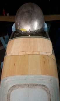
I then set it in place and secured it with a couple long sheetrock screws.
And then continued to fill in the gaping hole atop my nose section.
And finally got the canard mounting area hole, between F28 and F22, filled in.
As you can see, I also found a perfect candidate block of big blue foam to fill in the front top part of the battery compartment, which sits immediately forward of the Napster bulkhead.
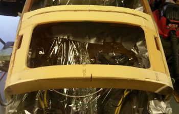
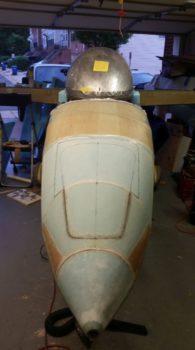
Here’s a front view of 2 of the 3 nose sections filled in with foam…. obviously needing some shaping to be sure.
Here’s a couple of pics of the urethane foam plug sanded close to shape.
Another front shot of the foam, roughly shaped at this point.
•••
14 June 2018 — Today I set my sights on the aft side of the nose: the cover.
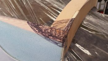
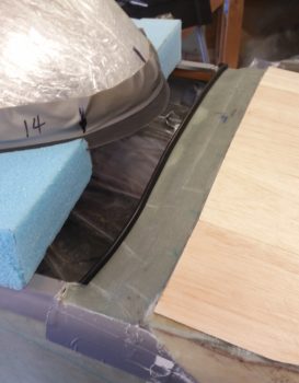
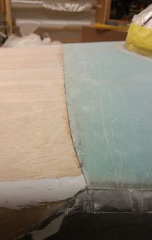
The first order of business was to sand a depression on the entire front side of the urethane foam plug that abuts the aft side of the intermediate bulkhead. This depression –or elevation adjustment– is required to help match up the nose glass level between the aft side cover and the front side nose glass. Since a layer of tape, then a couple plies of BID followed by strips of 1/16″ thick Basswood will be employed to create the base of the aft nose cover, I transitioned the urethane foam plug to be a bit deeper than a narrow mixing popsicle stick (~ 0.080″).
Here you can see the depression below the edge of the intermediate bulkhead.
After some more pondering, thinking and assessing, I then made the command decision to move the break line between the forward canopy opening and the nose to intersect with the angled edge of the aft nose cover right at the sides where the angle ends and transitions into a small length that traverses aft to intersect with the outboard ends of the glare shield… this segment is just along the top of the longeron for a few inches. This will allow the canopy skirt to cover up (hide) the cover segment along the longerons and will give the appearance of a converging 3-line intersection: ONE single line along the longeron, the canopy break line across the top of the nose, and the angled aft-up-sloped cover line. Think of a sideways “Y” for visualizing it a bit better.
I had originally envisioned the front break line of my canopy to be a bit more curvy and sexy, but decided to make it a bit straighter across the front with some curve at the outboard edges. I think this will be cleaner and simpler, allowing the lines to flow better visually, especially when the canopy is open since the canopy break line will parallel the glares shield lines. It also makes constructing the cover and canopy skirt considerably easier since I don’t have to carve/match a more detailed curve for the break line.
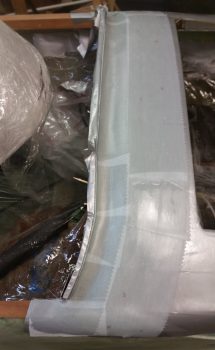
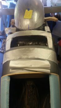
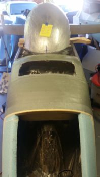
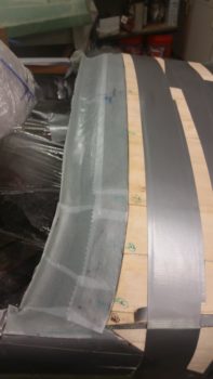
I then finished duct taping the aft nose for the eventual cover glassing. Rest assured, since I went through great lengths to minimize the depth and thickness of the tape (read: 1 ply) this took a fair bit of time and effort.
I also cut some glass away from the outboard edge of the glare shield layup to reglass it with the aft edge of the lower angled cover depression dialed in this time around. Here’s some side views of the taped up aft nose ready for some glass to create the aft nose cover.
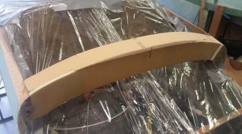
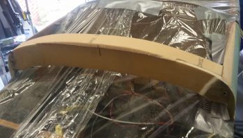
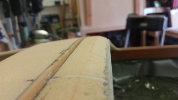
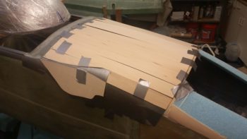
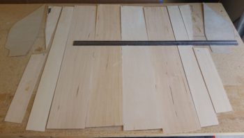
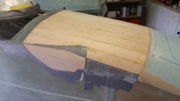
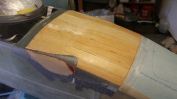
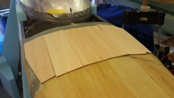
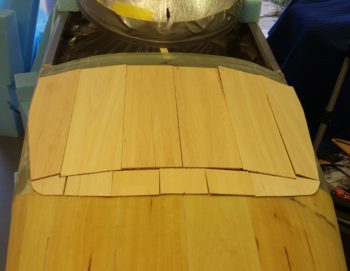
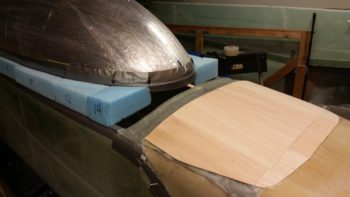
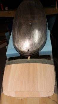
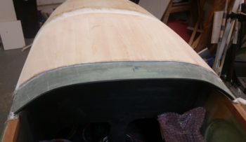
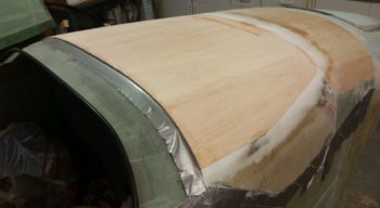
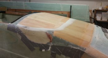
To bridge the obvious Grand Canyon sized hole I have in the top of my aft nose area, after weeks (actually years) of thinking I decided to go with thin, fairly flexible 4″ wide strips of Basswood… which is very close to Balsa wood in characteristics, just a tad denser and a little less fragile. It is still very lightweight nonetheless.

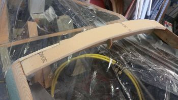
Here’s a quick shot of the Basswood measured to length and shaped to be mounted to the aft nose surface to create the cover. I know it looks a bit in rough, raw form, but when secured in place they will flow together and create a much more uniform shape than shown here. Also, I didn’t get a close up shot of it here, and it may not be readily apparent, but the aft edge of the combined Basswood strips make up the raised edge on the cover side for the break line with the canopy skirt.
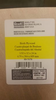
The more detailed piece of wood that makes up the cover’s edge inside the sidewall depression (shown above) is a slightly thinner piece of 1/32″ Birch plywood.
•••
15 June 2018 — I started off the day by taking a piece of paper and drawing a line down the center horizontally to create 2 panels. On the top I drew out my front nose layup and all the associated tasks for completing that layup. On the bottom I drew out the aft nose cover layup/construction and all the associated tasks for that endeavor. Then, with it on a clip board downstairs I added a a few more points to watch out for and another few tasks as I was thinking about my upcoming layups as I cleaned and organized the shop.
Down in the shop, I started by laying out my thin Basswood and Birch plywood strips in an organized manner off to the side.
Like I mentioned above, I then spent about 30 minutes cleaning and organizing of the shop. Wanna start fresh, right?!
With the glass cutting table cleared off I then cut all the BID required for the foundational underlayment for the wood strips above that will make up the aft nose/avionics top deck cover. As a point of note, the glare shield structure will get another ply of fresh BID to tie it into the wood strips/cover structure that will get laid in over the fresh BID.
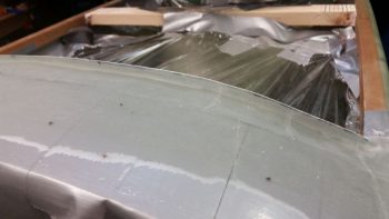
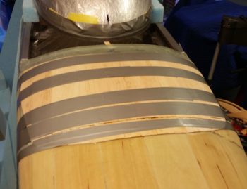
I then laid up all the glass on top of the protective duct tape barrier/mold releases I taped up last night.
Now, here I should have been a bit better on the uptake QA (Quality Assurance) wise and even noted my error in my blog last night when I was discussing getting the tape applied only 1 ply thick where I could. My plan –that I did not follow for some reason– all along was to apply at least 3 plies of tape on the sides of the fuselage where I made the depressions. So, I’m thinking the cover is going to fit a bit too snugly when I put it back in place once remove it… nothing that some sanding won’t remedy, but shows what lack of foresight and not following your own plan gets you: wasted time. Still, better to be a bit too tight in this scenario than too loose!
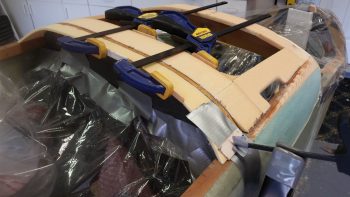
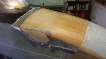
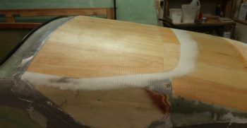
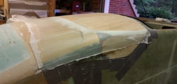
Nonetheless, as hairy going as it went for a while (with me thinking ‘who’s crazy idea was this to put all these damn wood strips on here?!’) herding cats with all the wood strips going off in different directions, I finally wrangled them all into some semblance of order and strapped them down like nobody’s business!
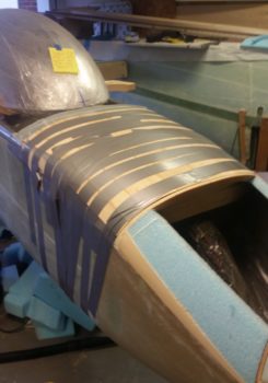
A bit of irony is that I would have used the thick Gorilla duct tape (as I had mentally planned to do) on the sidewall depressions for added thickness on the mold release, but I ran out of it using the really long strips I needed for more holding (“clamping”) pressure of the tape to keep the considerable pressure I needed on the wood strips –especially at the corners– in place. The 3M duct tape worked good for the 2 spots that I used it, but I’m thinking had it had to carry the entire load of keeping the wood structure in place, this would be an entirely different report altogether!
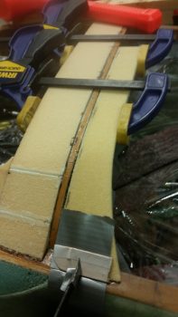
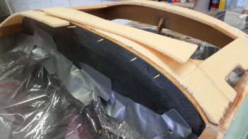
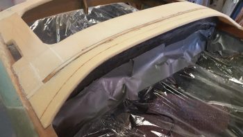
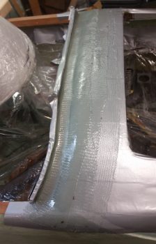
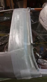
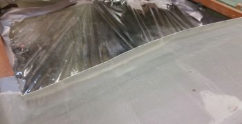
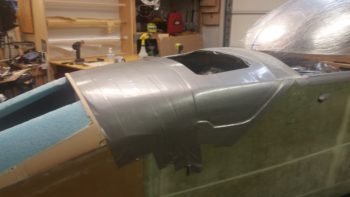
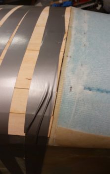
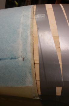
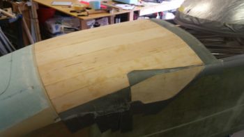
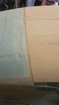
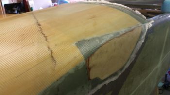
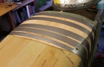
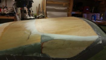
Here’s a shot of both the freshly re-glassed glare shield and the aft edge of all the wood strips, that when combined together collectively make up the cover-side raised break line interface with canopy skirt.
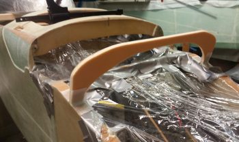
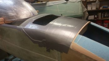
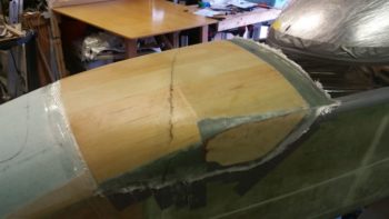
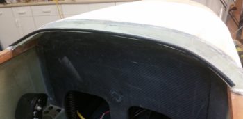
I grabbed these shots from both the left and right sides of the front nose vs aft nose cover intersection. This will be the one visible line that traverses across the nose other than the nose hatch door outline.
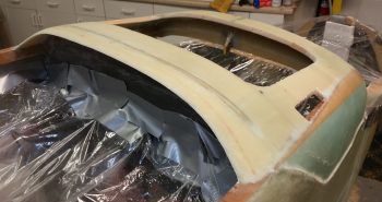
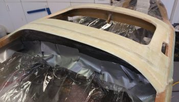
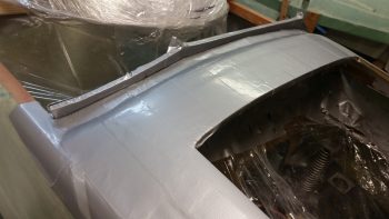
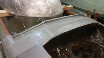
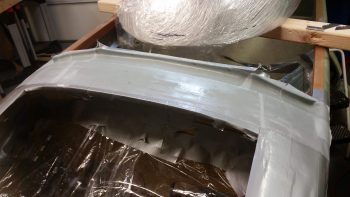
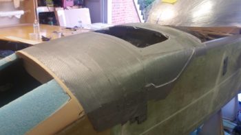
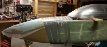
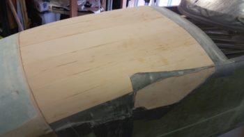
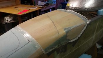
And a wide angle shot showing the profile of the nose after both the aft cover foundation and forward nose were glassed. I really am loving the shape of this nose, and it’s incredible how long and narrow it looks without the canard installed to break it up.
•••
17 June 2018 — As I was having my morning coffee I was thinking about the tasks that lie ahead of me for the canopy build today. I realized that for the very front of the canopy, the front skirt, that if I didn’t have the Aft nose/avionics top deck cover glassed that the skirt on the front underside would be off a bit. But then I reasoned, “How much?” I mean, we’re seriously only talking 2 plies of BID more [so I thought at the time] for the final glassing of the aft nose cover/glare shield . . . that’s not a huge thickness to contend with.
Ahh, but then I thought about accessibility. You see, I need the aft nose cover in place to glass in the canopy front skirt. Conversely however, if I don’t finish the cover first and then proceed with the canopy, then I’m locked out of working on the nose cover since the aft end of it would be covered by the canopy front skirt!
A pickle to be sure, but both issues resolved by simply knocking out glassing the final layup on the exterior of the aft canopy cover. Plus, since around 41 hours had passed since I finished the initial construction/glassing of nose cover, I figured it was plenty cured.
So that’s what I did.
I started by pulling all the tape off that had done its job admirably in holding the thin plies of wood in place and in alignment atop the aft nose structure.
I then got to work cleaning it all up. I pulled all the peel ply right away and then gave the exposed glass parts a good sanding.

I then grabbed the long sanding board and went to work. Since the aft nose cover was due to get 2 more plies of BID, as was the forward nose (1 ply for the entire nose, and 1 extra just for the nose hatch door… which I was going to extend aft) I then gave the intersection line –the now buried but visible intermediate bulkhead– a good working over to get the surfaces aligned with each other.
After a good 45 minutes of sanding and prepping, I was ready to start cutting some glass for the layup. I had been thinking about my layup schedule while I was sanding, so I listed that out and my layup task list in fairly short order.
And then I hit the proverbial brick wall!! Gasp! Ugh! Dammit! I was very, very close to being out of BID! I knew I was getting close, but obviously didn’t realize I was THIS close to being out. The implications on this was significant for today’s tasks specifically since if I had chosen to press forward with the canopy build, I don’t think I would have had enough… well, to do it all cleanly with singly pieces of BID per ply.
I did have enough for one ply to do the aft nose cover, so I simply changed my ply #2 from BID to UNI, so I could still get the cover glassed. I was planning on peel plying the “final” layup anyway just because in an essentially on-the-fly design like the aft nose cover, there may be some unknown variables that crop up requiring extra glass to be laid up over the existing final glass skin. Bottom line, if I need to layup more glass on the cover later on I’ll be poised to do so going the peel ply route.
I then rummaged through my extensive spare UNI bin (who uses this stuff anyway?? … haha!) and quickly cobbled together a ply of UNI for the aft nose cover layup. I chose to run the fibers across the nose to be perpendicular to the grain of the integral Basswood strips that make up the core of the cover.
Then I figured I would just forego the glass and simply varnish the wood… looks nice! Maybe a bit of stain?! HA! I jest…
I then undertook what turned out to be quite a considerably in-depth layup (don’t they all! … we Long-EZ builders are suckers! We always think things are going to get easier… or not take that long! heh)
So many, many hours later I was glad to put the lid on this baby . . . oh, yeah, forgot the peel ply.
So many, many hours later I was glad to put the lid on this baby . . . with peel ply!
Backing up pre-peel ply, I would like to point out that to streamline the contour of the aft nose cover to the maximum extent possible, it meant incorporating the “pointiest” part of the entire nose structure –besides the very front– which is still those pesky F28/front longeron ends that I trimmed down as much as I felt I possibly could!
You may have wondered (or could care less!) about the triangular strip of glass with no wood over it, which is in fact the very front corner of the F28 bulkhead and where the longeron ends. I’m kinda wishing I had taken it down at least another 1/8″, if not 3/16″ on each side. Still, I think these abrupt shifts in the nose contours are common to Long-EZ’s since you’re taking basically a square box and turning it into a long conical nose. So, don’t mistake my woulda, shoulda, coulda for displeasure, because I’m more than happy with this nose . . . yep, hind sight is always 20/20 on these builds!
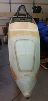
Another front view of the entire nose.
The aft nose/avionics top deck cover final layup really did take up about 5 hours total from start to finish.
•••
29 June 2018 — One thing I’m not overly pleased with on the current nose shape is that the ends of the F28 bulkhead protrude at the middle of the aft nose cover. As I deduced the issue down I realized that it wasn’t that these front fuselage “corners” weren’t shaped with enough ferocity to remove a good amount of material, but rather that the aft top surface of the aft nose/avionics top deck cover was simple deflated a bit in posture and was not at the contour height that it should be.
After mulling it around in my brain these past few days, trying to decide if I was simply going to live with it (it wasn’t a show stopper to be certain) or if I was going to contend with this issue . . . but how? I contemplated using some type of foam, be it pour foam or some standard build foam, but then with no narrow stock in abundant supply, I would have to order some or do a lot of sanding. Yuk on both of these options.
Since I only needed about 1/8″ added thickness, but uniformly added across the top, I again turned to lightweight strips of wood. Only this time just about the lightest wood you can get: Balsa wood. I figured that would be close in weight to say, 1/8″ Divinycell if I had gone that route, and I simply wasn’t going to mess around with urethane foam or pour foam.
I will also point out that my decision to add some thickness and fill in the aft top section of the cover meant that the canopy build would be delayed a day or so as well as I contended with this cover addition. The delay in the canopy build is simply due to the canopy skirt in the front interfacing with the aft nose cover, which must be completed first as a prerequisite task to dealing with the canopy’s front skirt configuration.
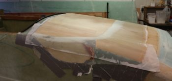
So while I was out running some errands I picked up some 1/8″ thick x 4″ wide Balsa wood strips. Upon returning back home I cut them up and set the strips in place on the top of the existing aft nose cover.
To help with the transition from the 1/8″ to the front side of the cover, I added a step using 1/16″ pieces of wood along the front edge of the 1/8″ thick strips.
My reference to “Tank-EZ” in the blog title is just a little blip on a term I have used in joking with Marco about how his Long-EZ would turn out heavy if he added an extra ply of BID or Kevlar to his aircraft structure. I was thinking about that today, since I did add a layer of glass for these wood strips to lay upon, but as a transition piece of fresh epoxied glass, and also as form of filler to help fill in the lower point across the aft side of the cover. Regardless, it was extra glass, as will be the top piece of glass that will go over all this. Although it’s not a ton of added weight, it is some . . . so I noted to myself that perhaps my Long-EZ is at risk of becoming a Tank-EZ!
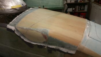
Here are a couple of shots with the new aft side wood pieces micro’d and glassed (bottom side) into place.
•••
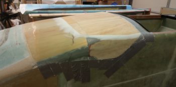
30 June 2018 — I knew that I was going to have to refigure, remark and re-tape my front canopy edge line since I added more height to the Aft Nose Cover on the back side of the cover…. using strips of 1/8″ thick Balsa wood. I was going to have to readjust this line anyway, I just wanted to double check with the new Balsa wood in place.
Since it had been well over 24 hours since I had added the Balsa wood strips, I removed the securing tape.
I then took the long sanding board and did a good amount of fairing in on the added Balsa wood.
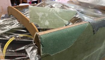
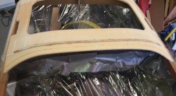
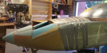
Here we have a wider angle shot showing the newly added foam pieces at the front of the canopy and the newly added 1/8″ thick Balsa wood plate on the Aft Nose Cover.
And a head on view of above.
•••
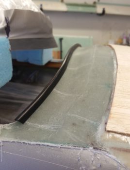
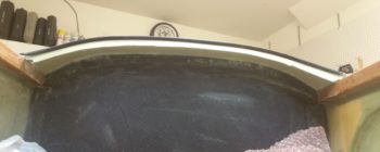
5 July 2018 — In prep for getting the canopy install much farther along than it currently is in order to haul the fuselage down to North Carolina, I measured, researched and then ordered some black trim for the aft vertical edge of the glare shield. The trim will serve two purposes:
- Keep from slicing open body parts that come in contact with the rather sharp edge.
- Compress slightly into a groove on the bottom of the canopy skirt to guard against incoming rain and moisture, wicking it to the outer edges of the glare shield/canopy.
I ordered the trim from McMaster-Carr a few days ago and it came in today. I have to say I’m quite pleased with both the fit and the look of the trim.
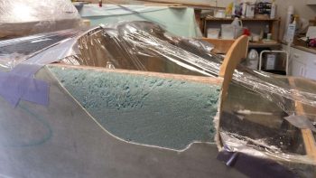
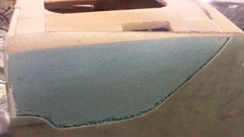
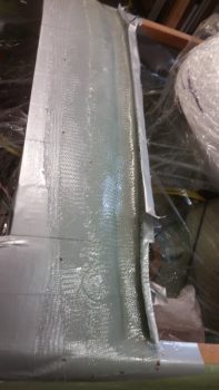
Here’s a bit closer look. When the airplane is finished to paint, the current green area of the glare shield will be a flat black, whereas the Balsa wood area will be painted whatever color the nose and canopy frame is painted (haven’t decided yet . . .).
•••
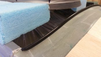
7 July 2018 — I started off today by cutting the glare shield’s aft edge trim/seal to length. I also tapered the ends so that it flows in nicely at the outboard edges.
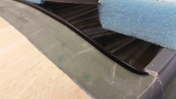
Here’s a shot of the right side cut/tapered aft edge trim/seal of the glare shield.
•••
12 July 2018 — Today I spent some time cleaning up the intersection between the canopy front skirt edge and the aft edge of the nose cover. This was the rough start to this process, but the lines were looking pretty good. I also took about 15 minutes to sand down the flocro transition around the Balsa wood on the aft nose cover.
•••
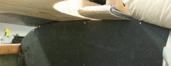
14 July 2018 — Part of cleaning up the fuselage after removing the initial canopy layup involved finally ripping out the foam and tape that I used as a form to create the glare shield. The pic below is the first time I’ve seen my glare shield without any form underneath of it.
And here’s a quick pick of the glare shield with rubber edging in place.
I then proceeded to spend as much time or more than I did removing the canopy on cleaning up the “melted” duct tape (very gummy) from off the top of the glare shield.
I also grabbed a shot of the underneath side of the glare shield structure.
Now, because I was sticking a knife underneath the canopy edge to work it loose, there was some slight collateral damage in that the right aft outboard corner of the glare shield got dinged up a bit…. as did the left side actually!
•••
15 July 2018 — I started off today by doing one final sanding of the aft nose cover –specifically where I added height by installing 1/8″ thick Balsa strips– and prepped it for glassing. I then applied a bit more micro to do one final smoothing of the transition between the added Balsa wood and the originally glassed aft nose cover.
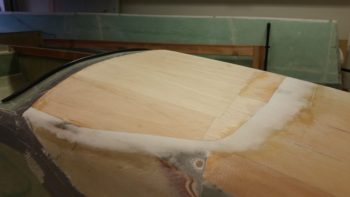
I also added some protective duct tape at the aft end to protect the intersection with the glare shield.
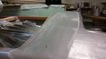
I then laid up the 1 ply of BID on the aft nose cover, which should do it for the major glassing on the cover.
I then peel plied the layup.
One last shot of the peel plied final major layup in the aft nose cover.
Jumping ahead a few hours –to stay on course thematically!– the layup on the aft nose cover was essentially cured. Here it is after I pulled the peel ply.
A view from the nose (always nice!).
•••
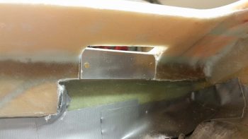
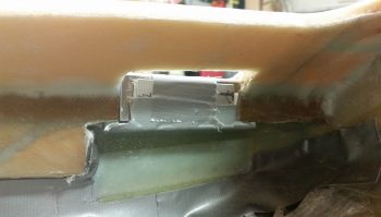
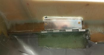
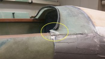
25 February 2019 — As a reminder of my aft nose cover shenanigans, part of the collective securing of this aft cover includes hinge plates attached to the movable/removable aft nose cover itself that are locked in place to longeron-mounted receiving hinge plates… one on each side of the avionics access opening. To be clear, this avionics access opening sits just forward of the instrument panel.
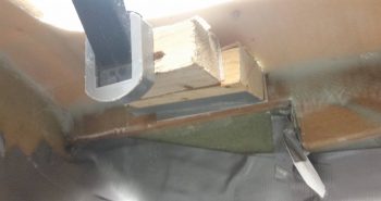
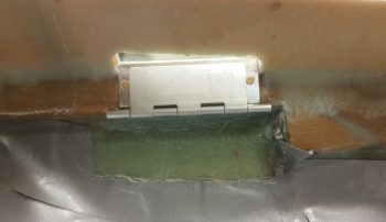
Below you can clearly see the near side and barely see the far side opening slit that allows the aft nose cover hinge plates to traverse through the nose structure to lock the aft nose cover into place to the longerons.
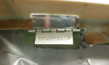
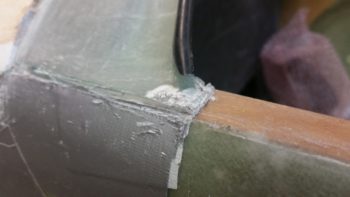
Below is a couple of shots of the mounted hinge plate assembly on the nose/longeron side of the aircraft. The hinge segment with the part # marking on it gets attached to the aft nose cover which obviously allows for the two hinge segments to interlock together.
Again, as just one part of a system [that also consists of CAMLOCs and screws] to secure the aft nose cover to the aft nose substructure, these hinge plates are secured to each other via a removable brass hinge pin that replaces the original hinge pin. This brass hinge pin –one per left & right side– traverses through the instrument panel and is held in place itself by a threaded bung floxed into the instrument panel.
This is my initial CAD-rendered drawing of the aft nose cover hinge pin.
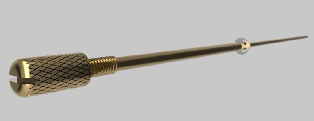
Part of the process to remove the aft nose cover is to unscrew the hinge pin from the instrument panel side and then slide the entire hinge pin assembly aft. The hinge pin assembly is retained both within the instrument panel and the longeron-side hinge plate (the very aft rung) via an E-style retaining ring (visible in both renderings above & below).
Just forward of the E-style retaining ring (to the right in pic below) the pin tapers down to the diameter required to lock the two hinge plates together (0.089 in.).
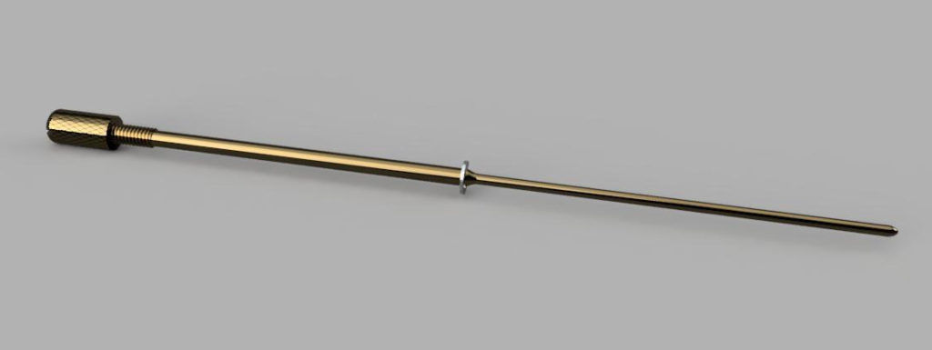
I drew up these hinge pins based off the best information I had available, and again, by using CAD I can fairly easily tweak any of the dimensions if need be.
•••
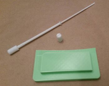
2 April 2019 — This morning I still had the small batch of white filament that comes with the 3D printer loaded. So I quickly 3D printed out a copy of both the aft nose/avionics cover hinge pin, and just the knob itself, to test the fit & function on the panel.
I had designed the knob to be both knurled and with a slot in the top end to use a quarter/coin to tighten/loosen it. However, I was just a hair narrow on my sketched slot (had meant to confirm the thickness of a quarter) so a quarter wouldn’t fit.
With the results of my newfound “test,” I set about working on the arduous 45 sec change in Fusion 360 so that the real one that I make will have the proper slot dimensions.
Tested and confirmed all for ~0.11 cents worth of 3D printer filament!
[Note: the green piece is the NG30 top hole cover/cap].
•••