
Nose Tool Box
The following information describes the building and mounting of a small nose tool box that I mounted in the battery compartment, just aft of the main PC680 battery.
[NOTE: See Chapter 25 for the finishing & painting of the nose tool box.]
11 September 2016 — Today I made the outward shell of the small tool box that I’ll be mounting just aft of the main battery, and just above the small emergency nose gear extension battery. Once I got the IBBS in hand, and figured out where I was mounting it, I then was able to finalize the tool box design that I’ve had in mind to incorporate for some time. Mind you, it’s not a very big tool box… but then again the Long-EZ isn’t a very big airplane!
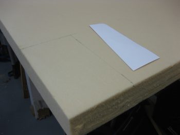
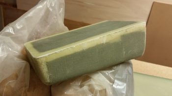
The template below shows the profile view of the tool box. It is 7″ tall, 4″ wide and is 1.5″ thick at the bottom and 2.5″ thick at the top. I plan to mount it with 4 button head screws on the front center face of Napster.
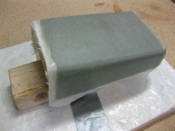
Since i didn’t have any readily handy blue foam for carving the tool box mold, I simply used a piece of the 2″ trash urethane foam.
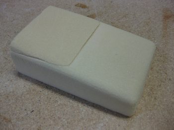
I then added a small 1/2″ (at it’s thickest point) piece of urethane and sanded it into a pleasing shape (as Burt would say!).
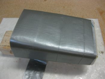
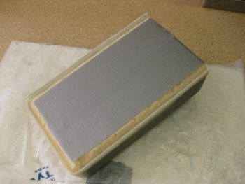
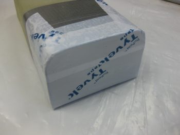
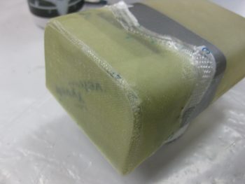
I then covered the urethane foam with duct tape as a mold release.
And then laid up 3 plies of BID on the forward 3 sides of the tool box. Since I want the tool box to have square corners on the back edges, I’ll use micro corners on the aft flat layup that will make up the back wall of the tool box. Then I’ll throw in a corner tape along the inside corners.
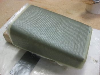
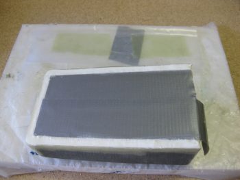
Because I want to have a nice micro finish on the tool box, I went ahead and peel plied it.
•••
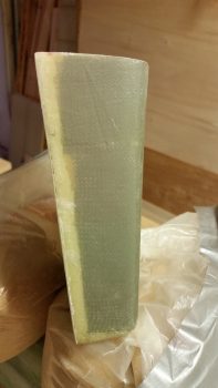
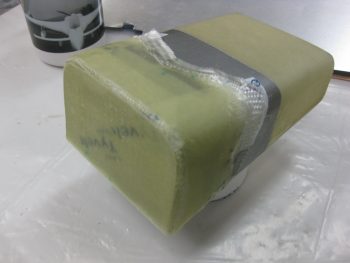
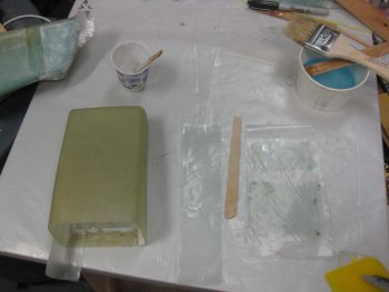
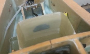
12 September 2016 — Today I work on laying up the aft wall of the tool box with 3 plies of BID. Since I want a square corner on the back side of the tool box (where it hangs on the Napster bulkhead), I need flox corners (actually, I’ll be using Flocro… heavy on the micro). So I marked & cut those out.
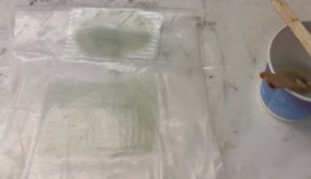
I whipped up some epoxy and some Flocro, with about 70% micro to 30% flox and filled in the wedged Flocro corner troughs. Also, as you can see in the pic below just above the tool box (light green rectangles), I cut up 2 sets of 2-ply BID and pre-pregged them to lay up over the IBBS Clickbonds.
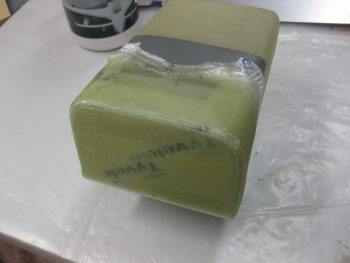
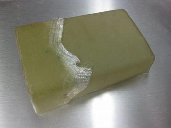
I laid up the 3 plies of BID on the aft wall of the tool box and then peel plied it.
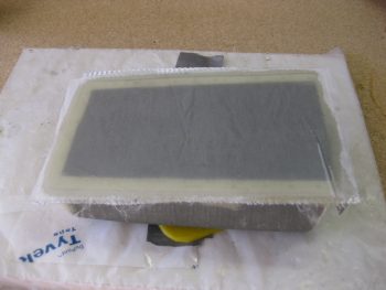
I then trimmed the edges with a Fein saw.
And then sanded them down.
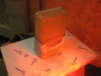
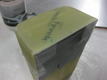
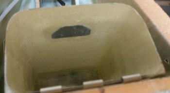
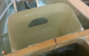
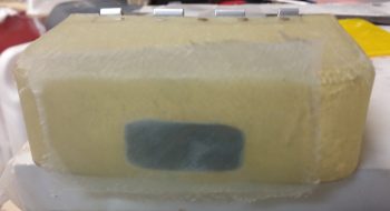
As my last officially task of the night, I dug the foam out of the tool box that I had used for a form. And then I cleaned up the inside just a bit.
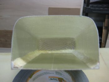
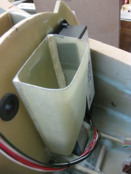
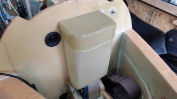
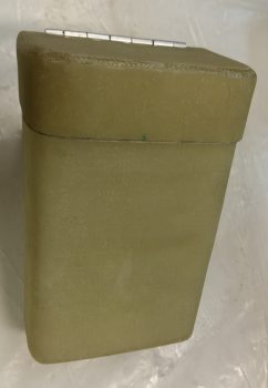
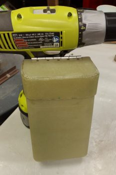
Then of course had to mock it up for a trial fit.
Here’s another shot of the nose tool box mocked up in place!
•••
1 October 2016 — Since I had the saw out, I grabbed a small aluminum hinge that I had set aside a few weeks ago for the battery compartment mounted tool box. I then cut a hinge for the tool box.
•••
6 October 2016 — Today I started back working on the tool box a bit. First, I sanded the micro corners and then glass adjacent to the interior aft corners on both sides. These corners will each get a 1-ply BID tape. I also glassed a couple of spots in the middle areas of the inside on the back wall, since these will get reinforce layups to beef up some areas on the back side in order to mount it.
After taping up the tool box, I tried to use some urethane foam to make a rounded over top cover, or lid, but the foam wasn’t strong enough to handle what I needed it to do.
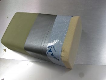
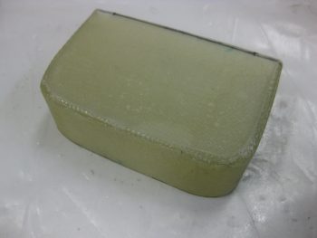
So I punted and simply taped up the top . . .
. . . and threw 4 plies of glass on it. This should work fine, but if not i can always redo it. I set it up to cure upside down so gravity would pull the wet lid glass straight down against the tape on my melamine working board, thus giving me a straight lid (if it works!).
•••
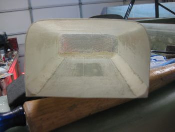
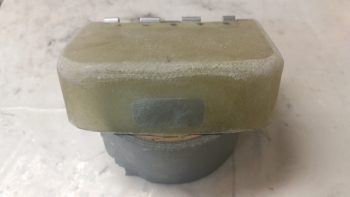
7 October 2016 — Today I started by checking last night’s layup for the nose tool box lid. I then pulled the peel ply and was glad to see that the layup looked fine.
Here are few more shots of the tool box lid at different angles.
It took a bit of effort, and a few choice words to finally get the lid pried off the protective tape I had covered the top of the tool box with. I needed to get the lid off so that I could consolidate my glassing efforts.
Here’s a shot of the big layups in action! In the middle I have a few prepreg setups ready to get laid up on the inside of the tool box. In fact, after these layups, all the interior tool box layups are complete.
The shot below was taken a few hours later after I knife trimmed the internal tool box layups and pulled the peel ply. I did a quick trim job on the tool box lid and wanted to see how it looked installed.
•••
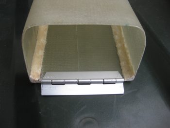
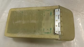
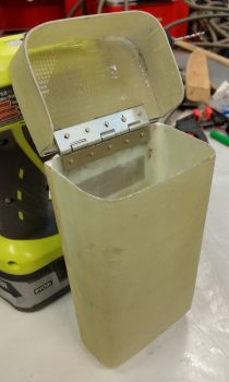
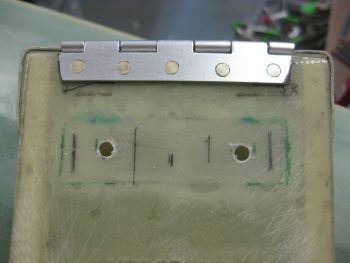
8 October 2016 — Today I went ahead & mounted the hinge for the nose tool box in place, with 5 rivets each side.
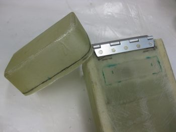
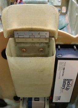
Here’s a shot of the hinge mounted to the lower “box” side of the tool box.
I of course needed to trim down the tool box lid, which I did.
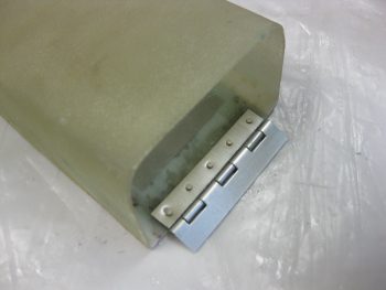
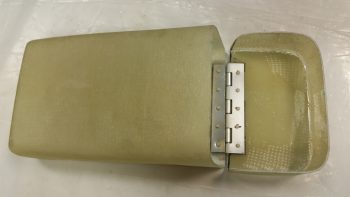
Once the lid was trimmed, I then riveted it to the hinge that was mounted to the tool box. Below pics are shots of the aft and front sides of the tool box lid hinge.
And here’s two “Action Poses” . . . ha!
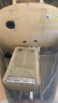
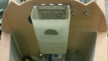
Finally, here’s a shot that shows a good portrayal of how it will look in the nose when opened for access.
•••
13 October 2016 — Today I decided to have a little fun and work on mounting my tool box in the nose battery compartment.
I had originally planned on using button head screws in four (4) places to mount the tool box to the front of the Napster bulkhead. As I pondered the mounting though, I just didn’t want have to deal with “wasting” two K1000-3 nutplates for the bottom mounts… nor did I want to have to try to work at the bottom of the narrow channel immediately behind Napster (made up of the 2 NG30 “goal post” arms).
Since the bottom attach points for the tool box don’t need to be screwed in or out to mount the tool box, and will be essentially forever stagnant in purpose, I decided to simply use Clickbonds as my attach points and even more simply just flox them in place into holes drilled into Napster. Now, the top two button head mounting screws will get K1000-3 nut plates and will be removable.
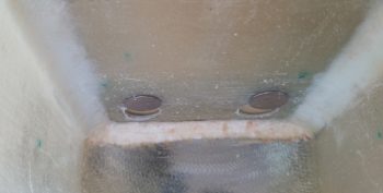
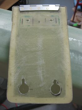
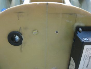
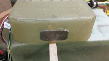
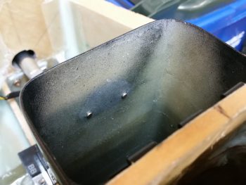
With my plan devised, I moved forward to set it in motion. I marked off the perimeter of the Clickbonds on the aft lower side of the tool box. I then drilled out the holes so that the Clickbonds could slide into the interior of the tool box. I then took a small drill bit and made notches for each actual Clickbond threaded shaft (albeit not as straight as I wanted them!)… as symbolized by the small black dot looking things at the top of the circles in the pics below.
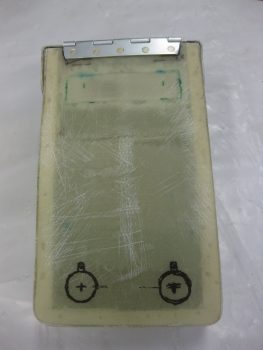
I then placed packing tape on the back side of the tool box to protect it from wayward flox. I also taped the Clickbonds into their respective notches using duct tape on the inside of the tool box.
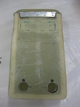
I sprayed black spray paint onto a stick and while wet applied it to the tips of the Clickbonds. I then carefully & gently lined up the tool box into its final mounting spot and pressed the lower tool box –and the Clickbonds– against the face of Napster. I then had 2 marks to identify my drilling points. I used the long 1/4″ drill bit to make my initial holes, but at an angle since space is tight in the nose. I then cleaned up & straightened the holes using another bit, by hand.
I then whipped up some flox and filled in the 2 drilled mounting holes. I also slathered some onto each Clickbond and set the tool box in place. I taped it in place with duct tape and let it alone to cure.
•••
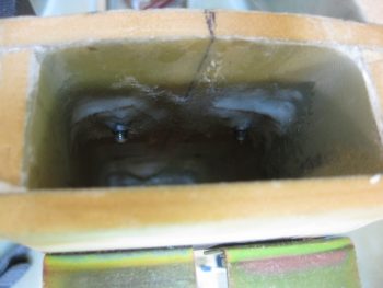
14 October 2016 — Today I removed the tool box from its lower mounts. To do so, I removed all the tape from the inside of the tool box that had kept the Clickbonds in place, and then I very slowly worked the box back & forth to free it from some of the cured flox. After wiggling it back and forth with a very slight prying action it popped free after about 20 seconds.
I then removed the protective packing tape from the back side of the tool box, and cleaned up the holes just a bit. Then I remounted the tool box to see how it fit. Ahh, nice & tight against the Clickbonds that were pressed into service as mounting tabs!
The fit is so tight the tool box stays in place mounted onto jus the lower tabs, even when I open & close the lid. Obviously once I get the upper 2 button head screws drilled & mounted it will be nice & secure. I’m extremely pleased thus far on the way this tool box is working out!
•••
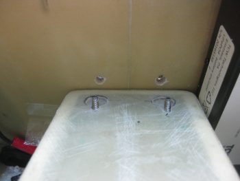
15 October 2016 — Today I decided to knock out the mounting of the nose tool box. I drilled two #10 mounting holes through the upper tool box mounting hardpoint. I had to ensure to drill the holes inboard just a bit more than I had originally planned to make sure the nutplate assemblies could be mounted properly on the aft side of the Napster bulkhead.
Here’s a shot of all 4 tool box mounting holes.
I then made up a couple of K1000-3 nutplate assemblies using 1/16″ phenolic as a base.
I then mounted the tool box on the lower mounting tabs, finalized its position, and marked the upper mounting hole positions using a scribe. Then I drilled the mounting holes through Napster using a #10 bit.
I floxed the nutplate assemblies in place using two AN3 bolts to hold them in position. Then I added a ply of BID over each nutplate assembly.
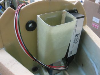
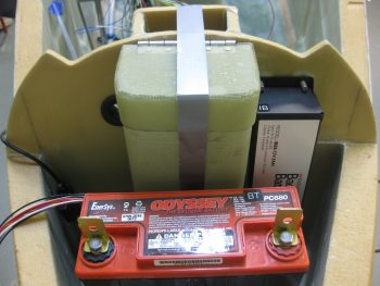
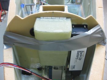
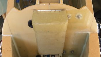
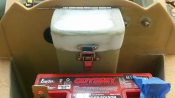
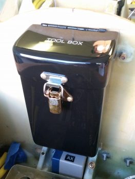
So… here it is. My tool box is officially mounted! I included the IBBS in the pic to show how tight the quarters are in the nose, but so far it all fits.
•••
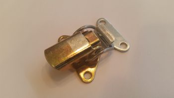
13 April 2017 — Since I like to consolidate my epoxy & glassing endeavors, today I figured I would layup some reinforcement plies of glass on the nose-mounted tool box to allow me to mount a latch on the lid and body of the tool box. I have a couple of styles of Dzus cowling latches, and decided on the most diminutive style of the ones I have on hand to allow better clearance of opening the tool box with the least chance of scraping knuckles on the main battery, which resides immediately forward of the tool box.
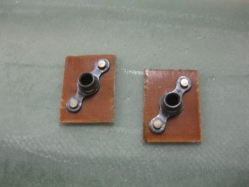
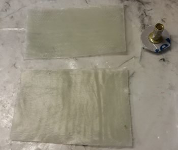
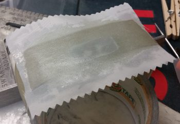
After figuring out my tool box latch, I decided to use 2 plies of BID for reinforcement on the tool box. For a bit more oomph, in addition to the 2 plies of BID, I cut some latch reinforcement plates out some of 0.5mm aluminum that I still have left over from Germany. Once I cut the reinforcement plates (shown below) I could then determine the size of my BID plies. I cut the BID plies, and per my norm I put them in plastic to prepreg them. I then whipped some epoxy and wetted out the 2 sets of 2-ply BID in the prepreg setups.
Here’s a shot of the 2 sets of 2-ply pre-pregged BID and the RivNut Adel clamp threaded insert hardpoint that will get floxed into the sidewall.
Then, using the flox I had just mixed for the Adel clamp RivNut, I floxed the aluminum latch reinforcement plate to the INSIDE of the tool box (I previously sanded the inside face of the tool box and the outside edge of the lid).
Since there’s not much clearance between the inside of the lid and the outside of the tool box body, I then floxed the lid aluminum latch reinforcement plate to the OUTSIDE of the lid flange.
I then laid up the 2 plies of pre-pregged BID inside the tool box onto the aluminum latch reinforcement plate.
And did the same for the lid. These layups were just a tad squirrelly in that for some reason the reinforcement plates really wanted to slide off their marks when I applied the glass. My thinking is that my flox wasn’t thick or sticky enough to keep them in place, since I used a bit more wet flox early on as I was mixing it up. I got them set in the end, but with a bit more fiddling than I would have preferred.
I then added peel ply to inside tool box reinforcement layup.
And the lid reinforcement layup.
Jumping ahead a number of hours, here’s the inside tool box latch reinforcement layup after I pulled the peel ply.

You can see, with the glass so clear it was fairly EZ to work the glass on the inside of the box while looking at what I was doing from the outside of the box. This shot is after the reinforcement layup had cured.
I pulled the peel ply on the tool box latch lid reinforcement layup and then did some much needed sanding on the lid.
•••
17 April 2017 — Today I spent about half an hour mocking up the location and configuration of the nose tool box Dzus latch. I started with the bottom latch assembly, got it situated and then drilled the rivet holes. With the bottom latch assembly set in place, I then determined the “exact” location of the top latch assembly, got it set up and drilled the holes for it as well.
With the latch parts ready to be riveted into place, I then pulled them off and started prepping the tool box parts for eventual paint. I want to get the surface painted before I mount the Dzus latch onto the tool box. Now, if I can just finalize a color choice!
[NOTE: Again, see Chapter 25 for the finishing & painting of the nose tool box.]
•••
13 May 2017 — Today I headed over to my EAA Chapter 186 buddy & RV-10 builder, Jeff Karrel’s place for some help riveting the lower latch to the tool box, since he of course has all the big gun riveting tools required to do such a job. The rivets on my lower tool box latch are just too low for me to get to with my hand rivet squeezer.
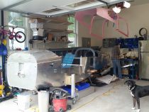
Jeff showed me his beautiful RV-10 build (that thing is HUGE!) and after about an hour of shooting the breeze we actually got to work. Jeff pulled out a deep-necked pneumatic rivet gun and asked me if I wanted to do the honors. I did, but I wanted him to do it so I could have yet another builder’s “mark” on my build as well!
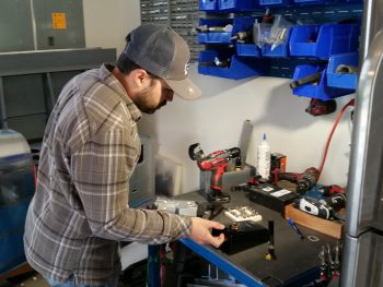
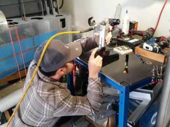
Here’s some action shots of Jeff driving the rivets on my lower tool box latch. Also, you can see his incredibly clean RV-10 build in the foreground. He is just finishing up riveting the tail section to the front fuselage… exciting stuff.
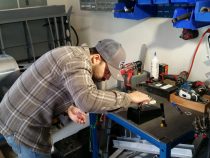
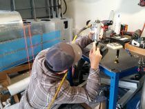
One more shot of Jeff driving home the rivets on my tool box . . . huge thanks Jeff!
After another couple of hours talking shop with Jeff, I then drove home and set the tool box back in its proper spot. I then grabbed a shot of the rivets Jeff set in place. It’s all coming together!
•••
14 May 2017 — Today I gathered up my tool box lid, located the upper latch piece and the requisite rivets. I then drilled out the half-painted-over holes and proceeded to rivet the upper latch piece in place.
Before assembling the tool box for good, I taped up all of the lower tool box body to protect it from paint except the hinges. The hinges required a bit of touching up since I had previously broken through to gray primer while wet sanding the lower tool box. I then prepped the hinges by sanding them lightly (again) and then cleaned them for paint. Finally, I took it outside and hit the hinges with a couple coats of gloss black paint. [No pics for this task].
•••
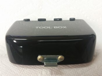
15 May 2017 — Today I finally assembled the tool box and put it checked it out.

I then made a video that discusses not only the tool box operation.
•••