
The Long-EZ N916WP project officially begins on 24 April 2011!
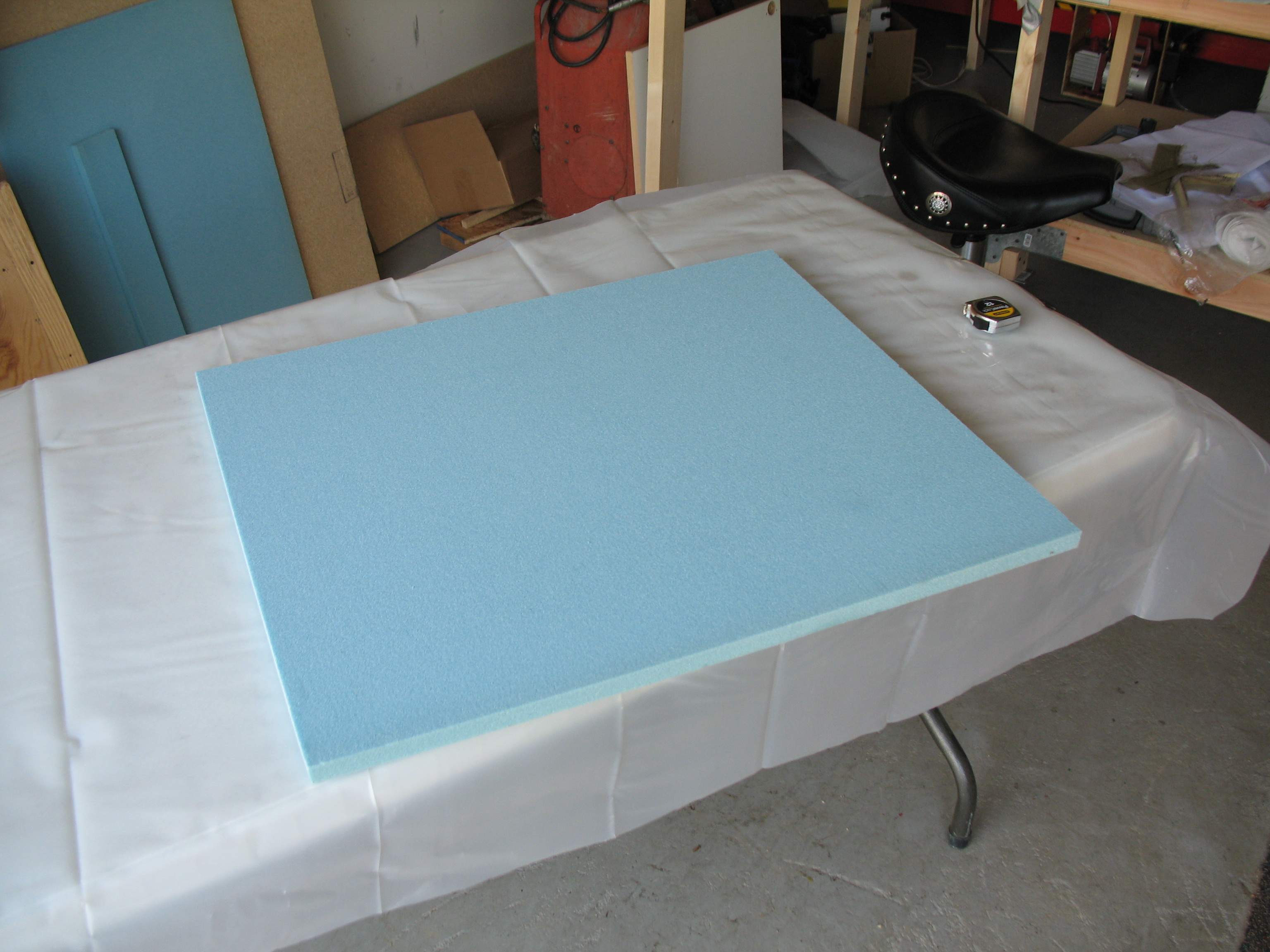
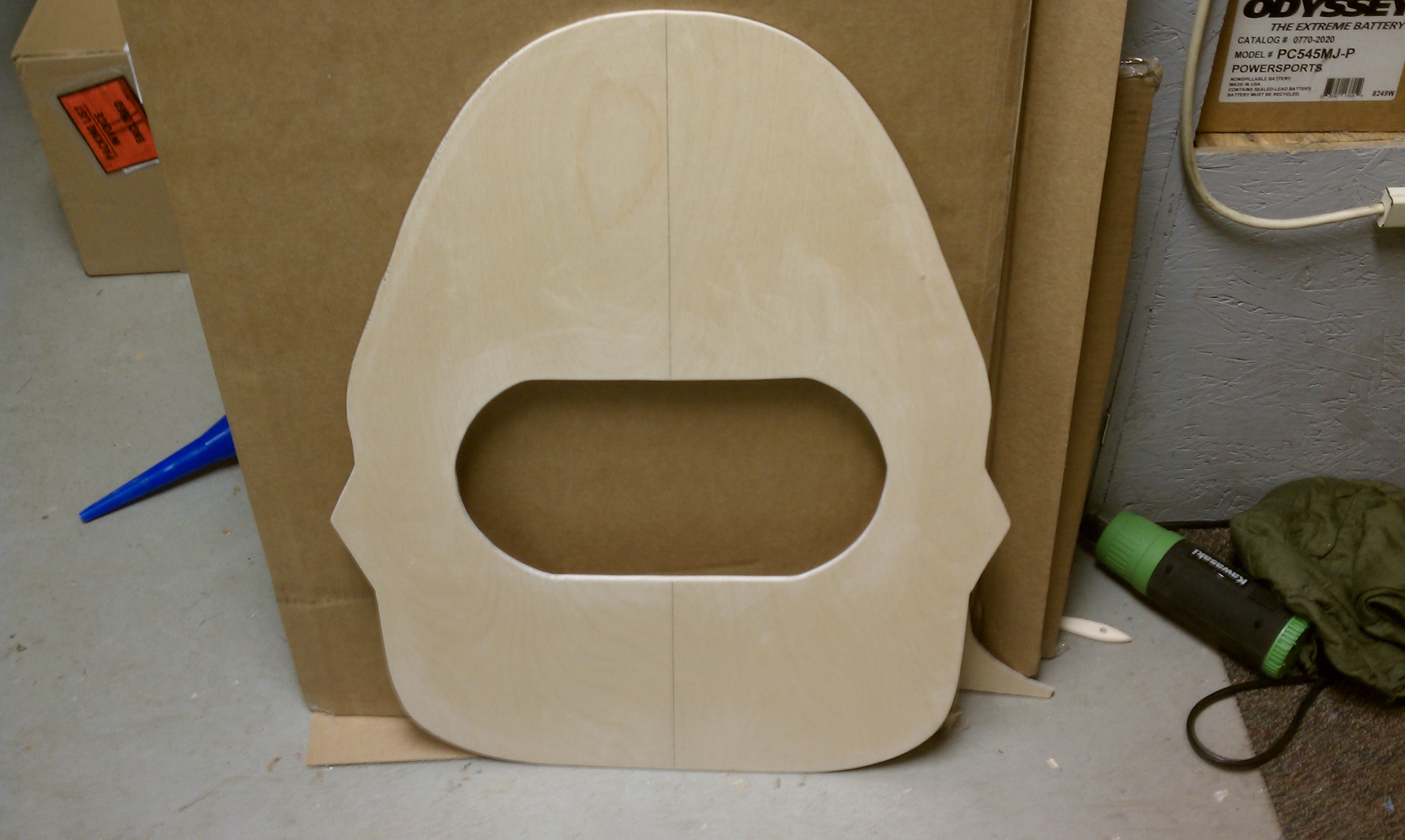
The first chapter in the plans for actual aircraft component construction is Chapter 4, which covers the building of all the bulkheads that will make up the structural cross-sections of the fuselage. Below is the first bulkhead to be constructed: the front (Pilot’s) seat back.
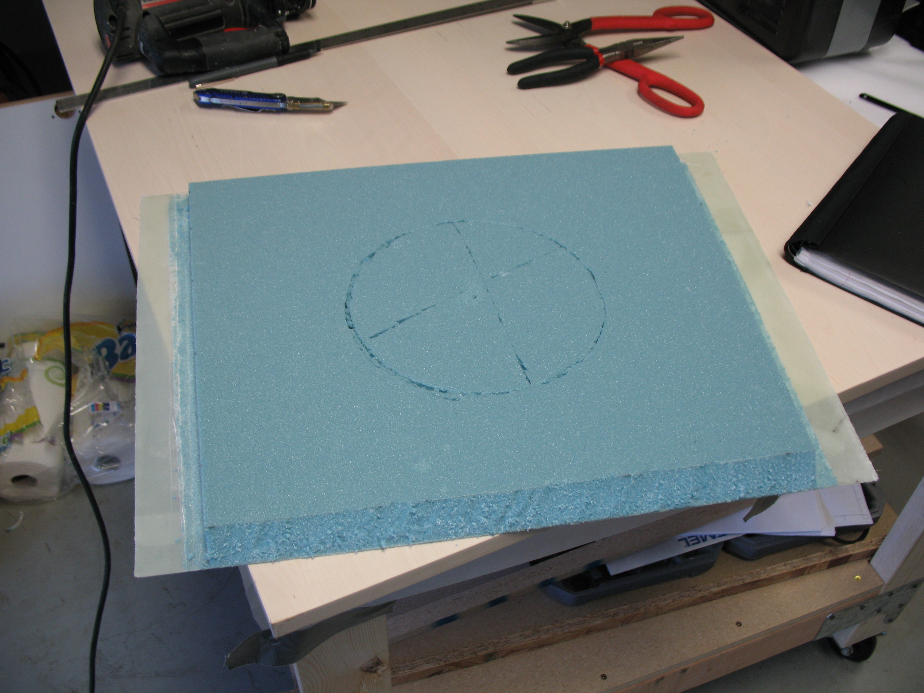
Chapter 4 — Step 1 of 4: Front Seat Bulkhead

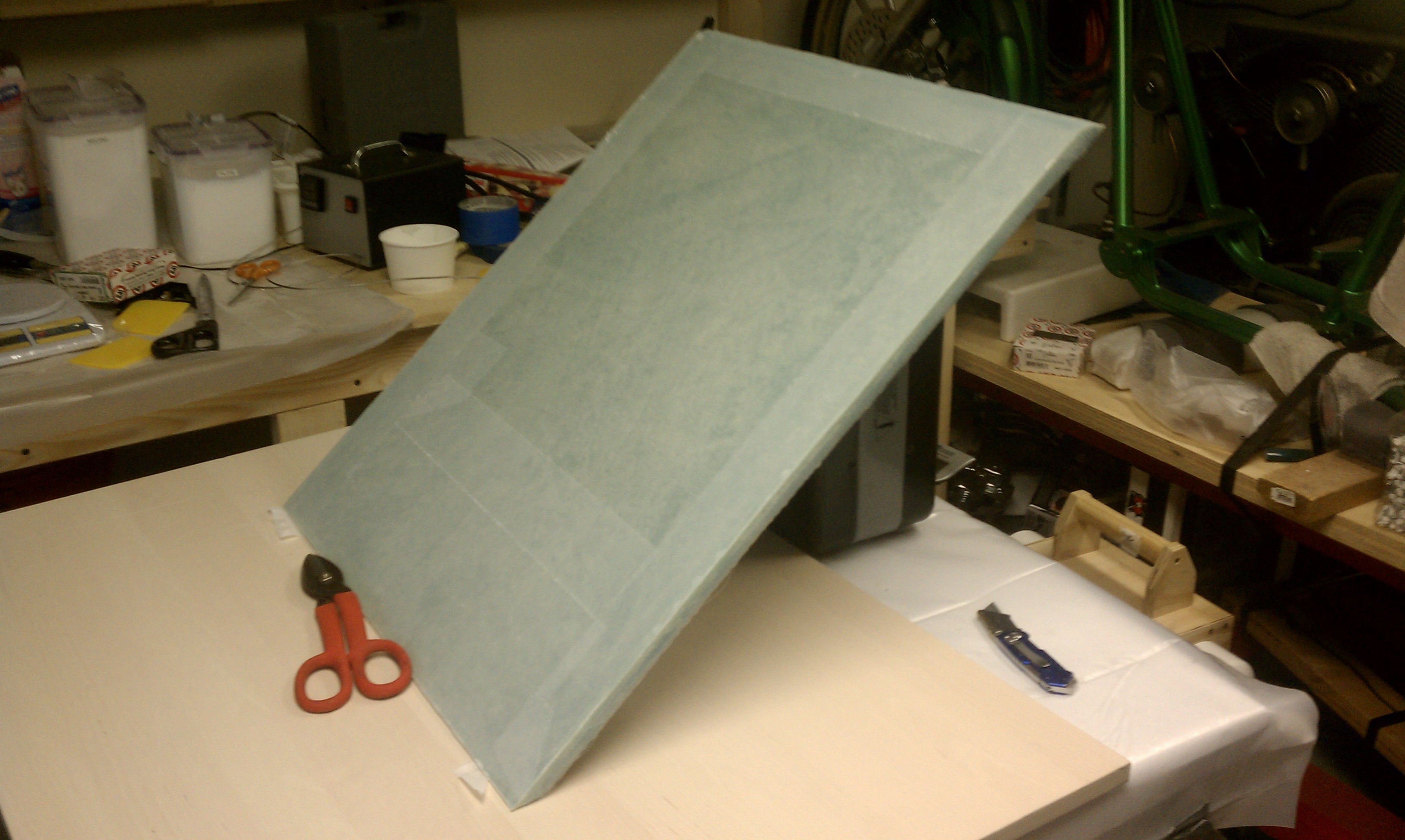
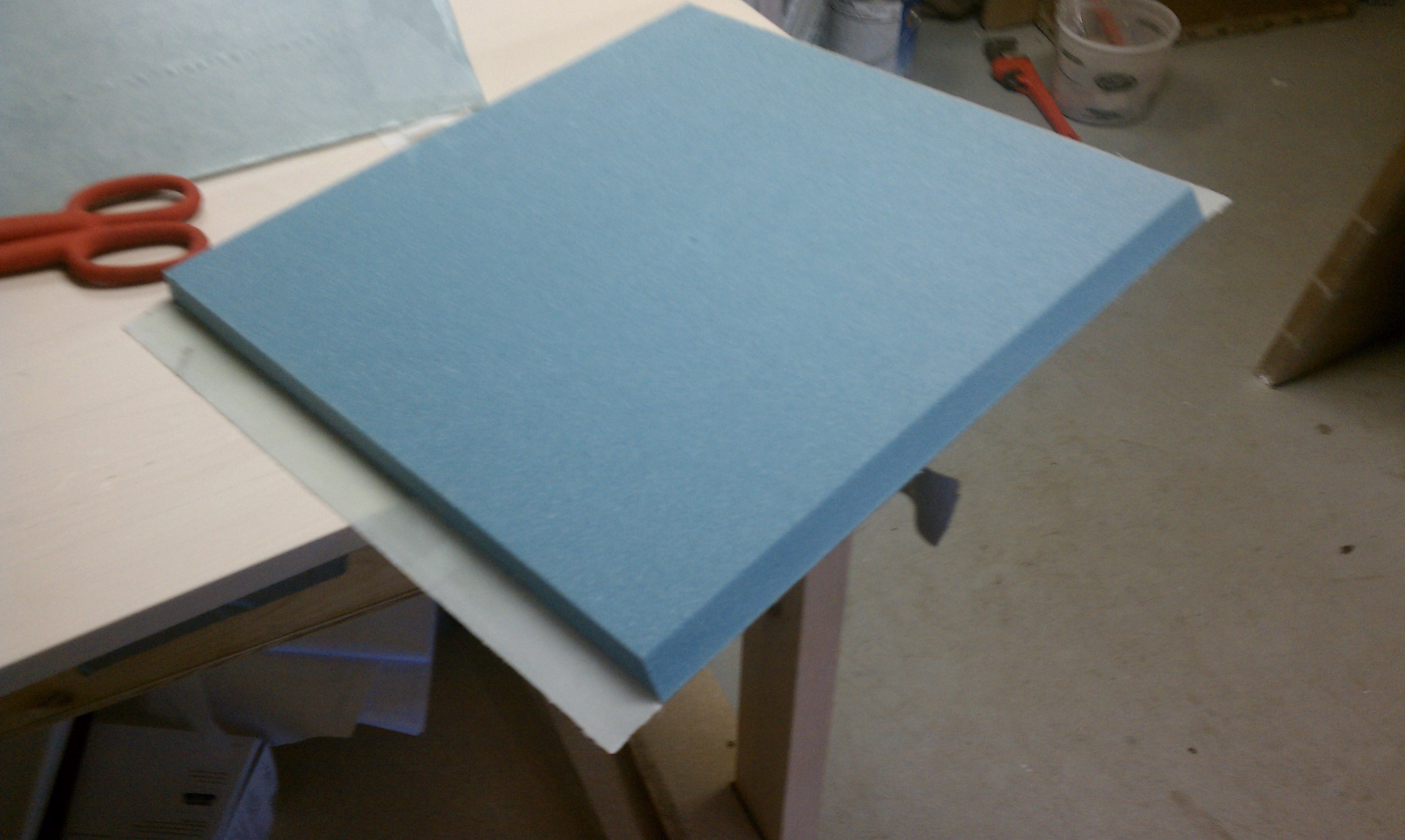
Front seat foam cut & shaped
Front seat back bulkhead
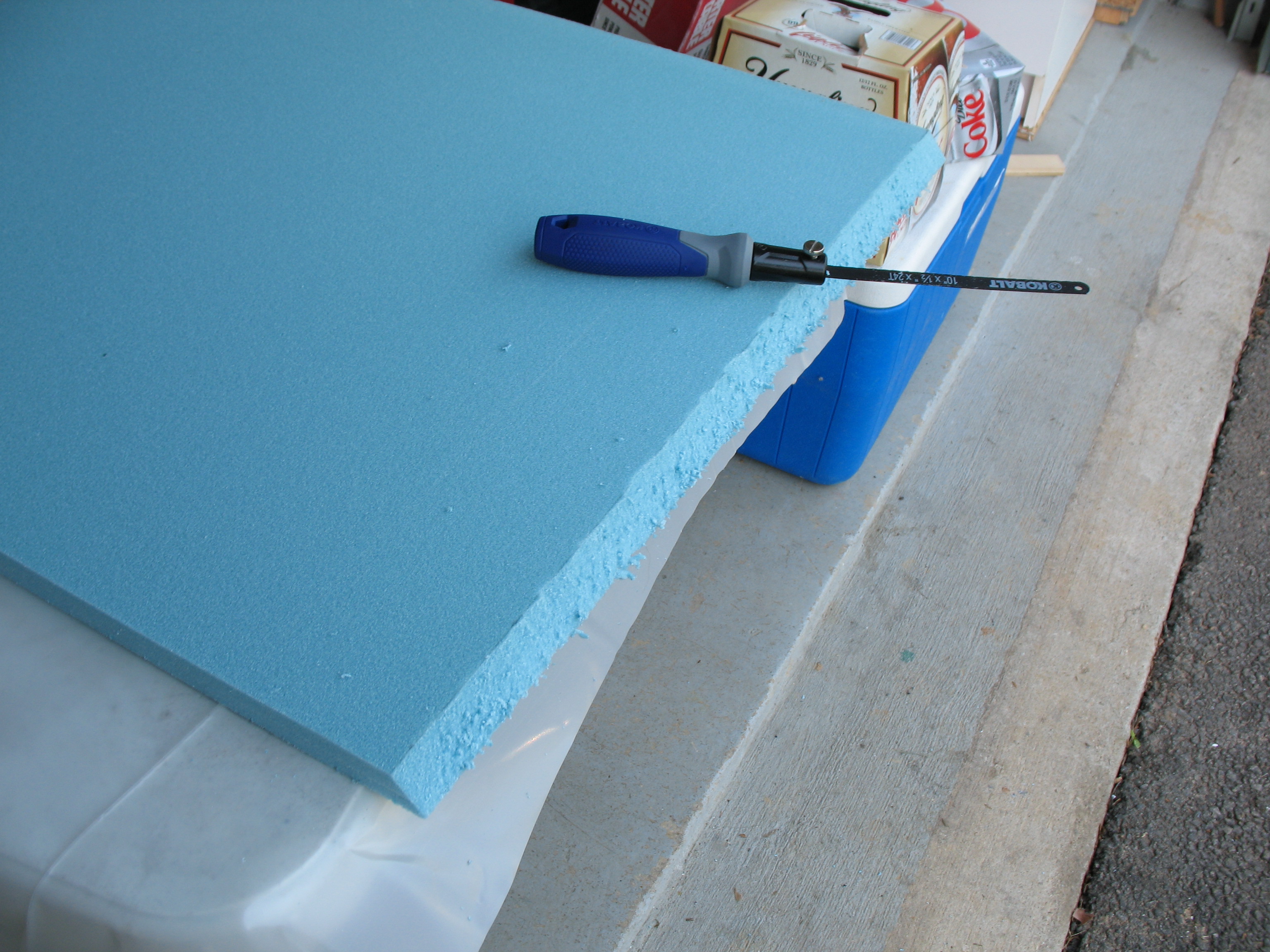
Angling front seat back edge
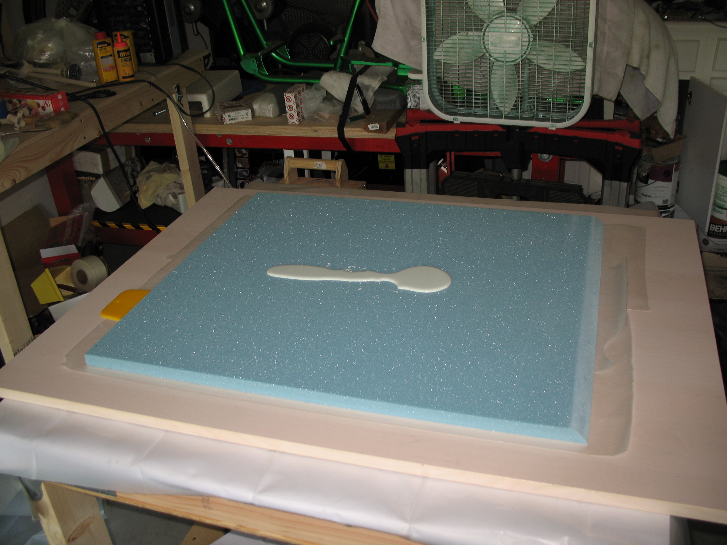
Micro’ing front seat back bulkhead
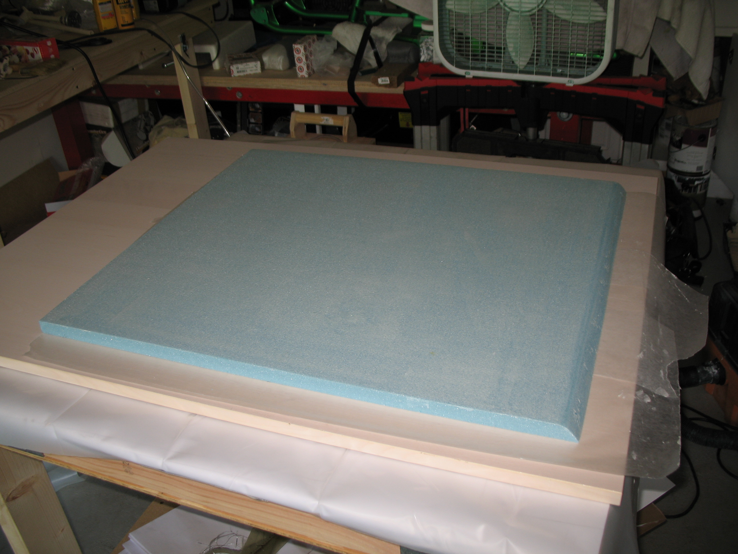
Micro applied & spread
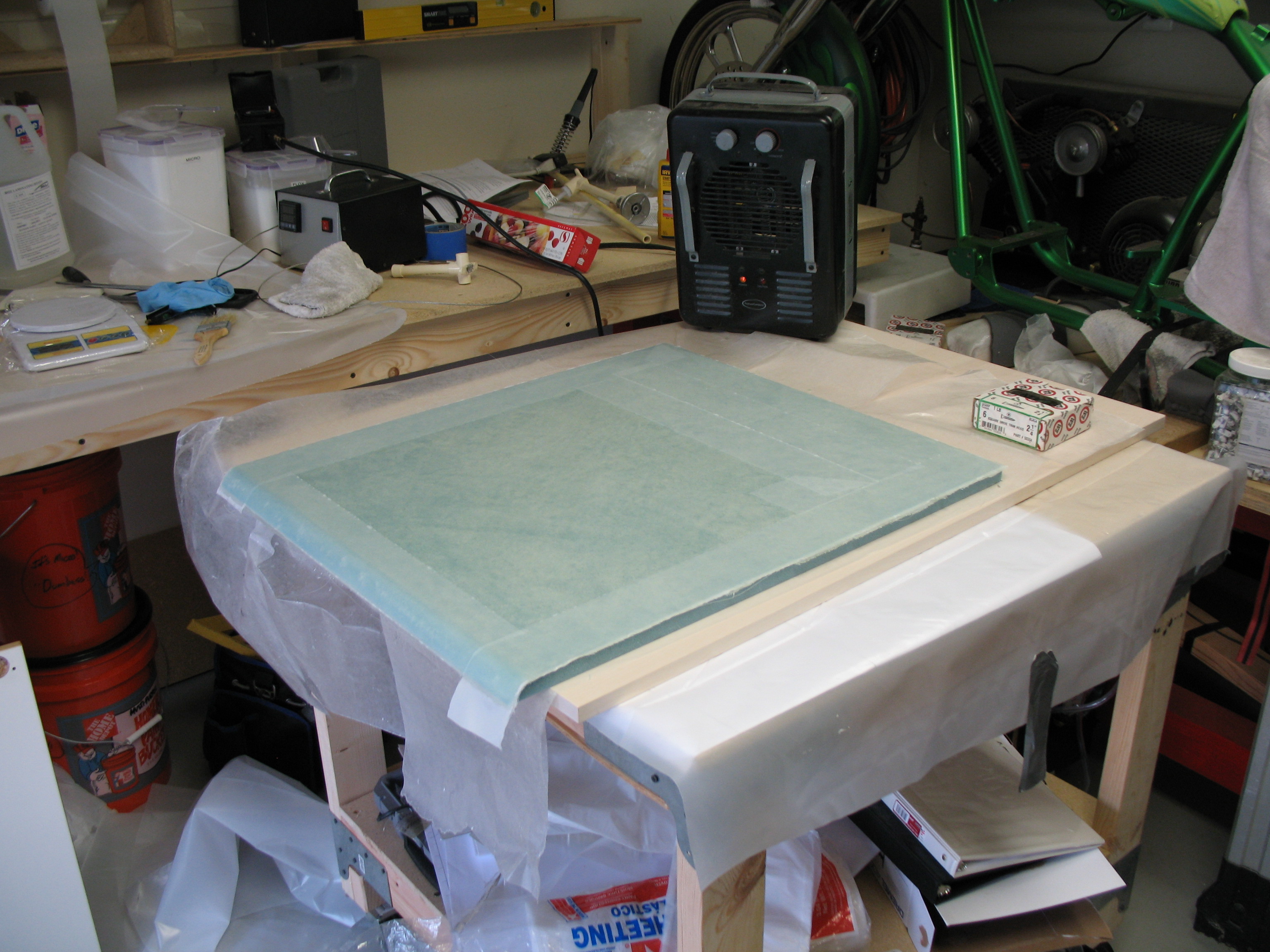
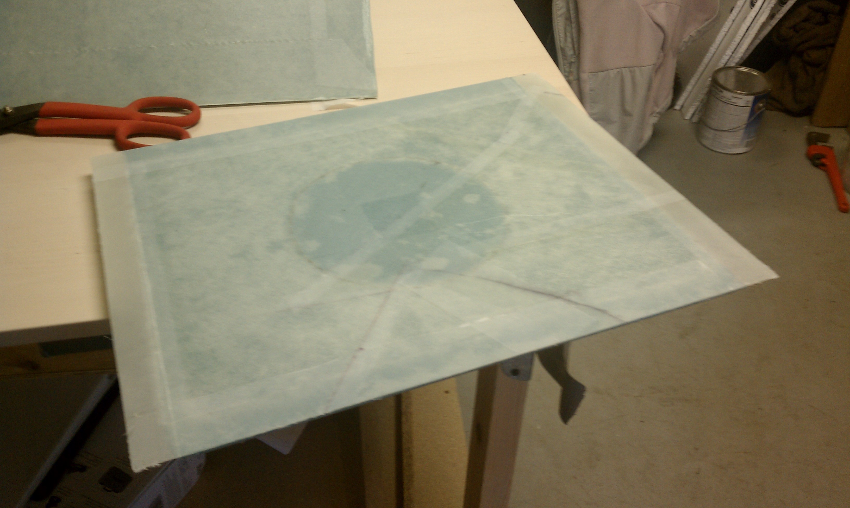
Front seat back glassed & peel plied

Glassed side #1 of front & rear seat bulkheads
Chapter 4 — Step 2 of 4: Rear Seat Bulkhead
25 April 2011 – The cured first sides of the front seat and rear seat bulkheads. →
26 April 2011 – The work continues on the front & rear seat bulkheads. ↓
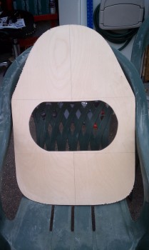
#1 – A shot of the front seat bulkhead, glass completed on both sides.
#2 – Start of the foam prep on the backside of the rear seat bulkhead.
#1 Front Seatback Bulkhead
#2 Rear side of Back Seat Bulkhead
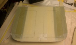
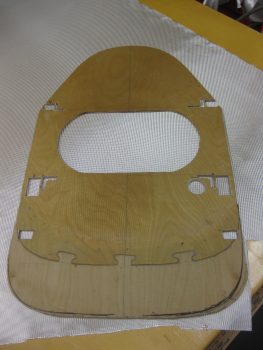
Below is the front side of the rear seat bulkhead. It doesn’t look like a very nice glass lay-up on the front because it wasn’t! I started out trying to save as much glass as I could, so I was piecing together remnants to save glass. Boy, did I ever grow out of that in quick order!
#3 Front side of Back Seat Bulkhead
•••
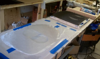
27 April 2011 — I shaped the rear side of the back seat bulkhead, and then vacuum bagged the fiberglass layup on the back side of the rear seat bulkhead, which was the second and final layup on the rear seat bulkhead. The vacuum bagging worked really well. The only down side is that with the hole in the middle of the seatback, it caused the plastic to wrinkle and that transfers some to the layup and leaves some epoxy ridges that have to be sanded down later. Again, I was very happy with the outcome.
Prepping foam shape on rear side of back seat
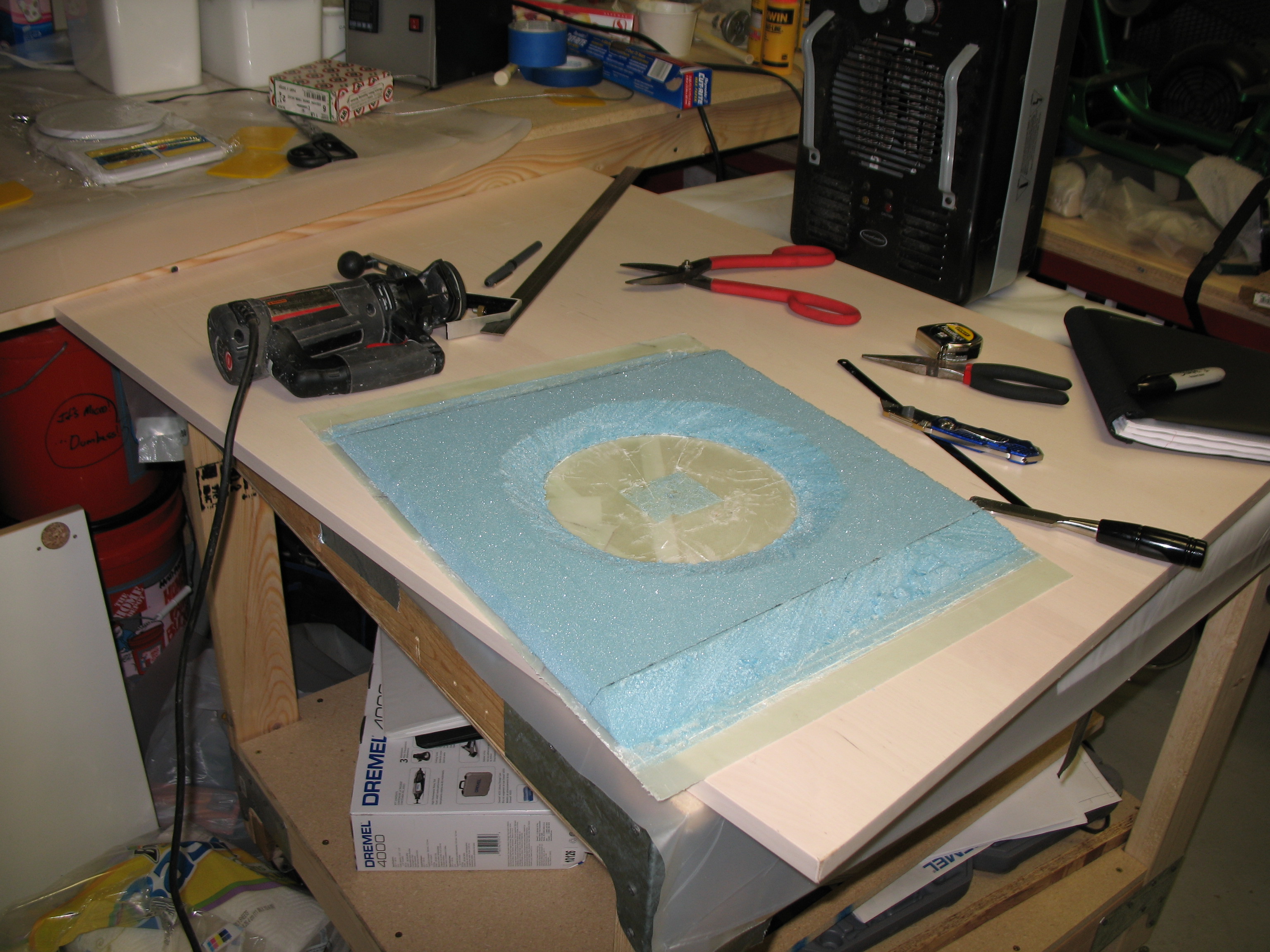
Rough stage of foam contouring on rear seat
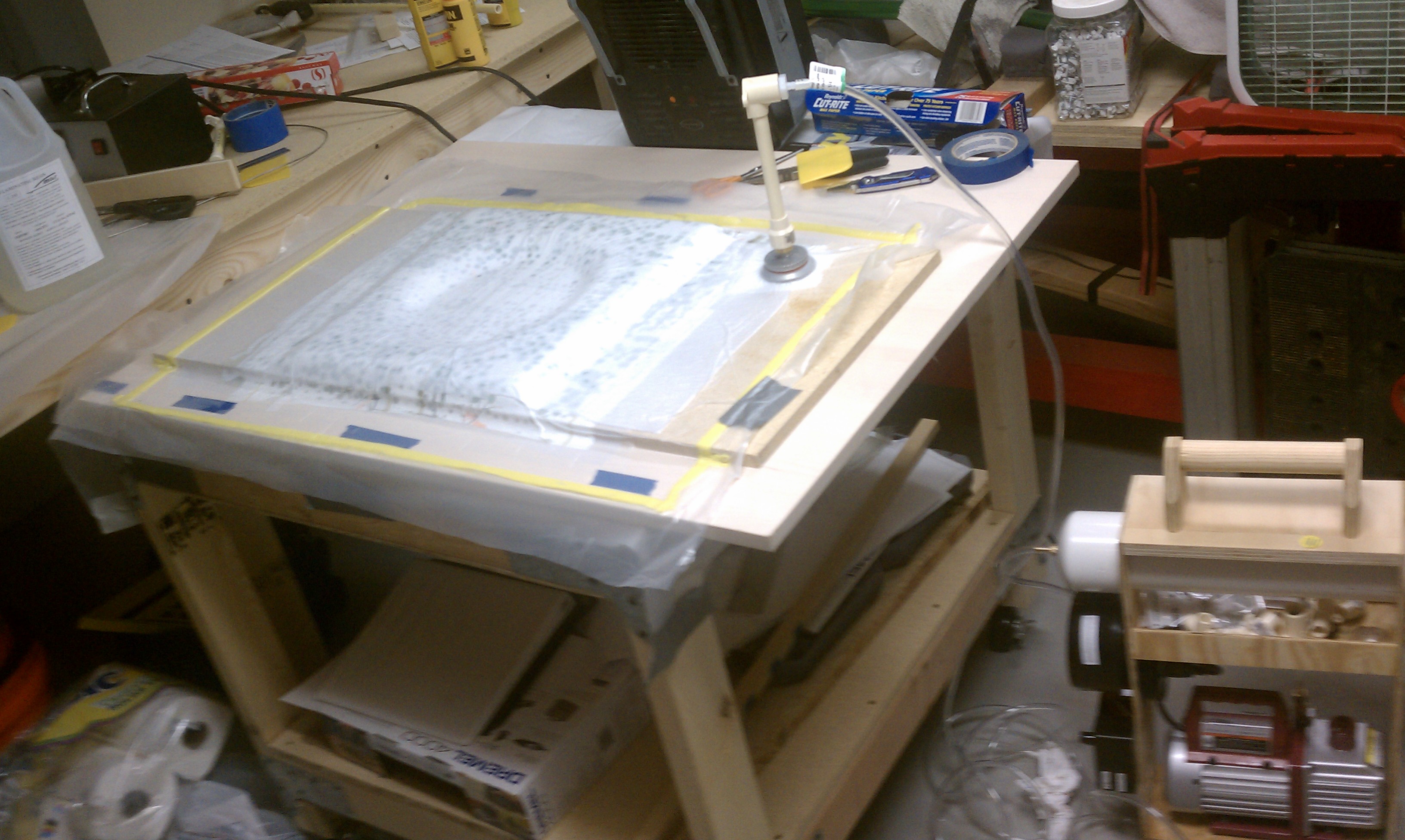
Vacuum bagging rear seat final glass layup
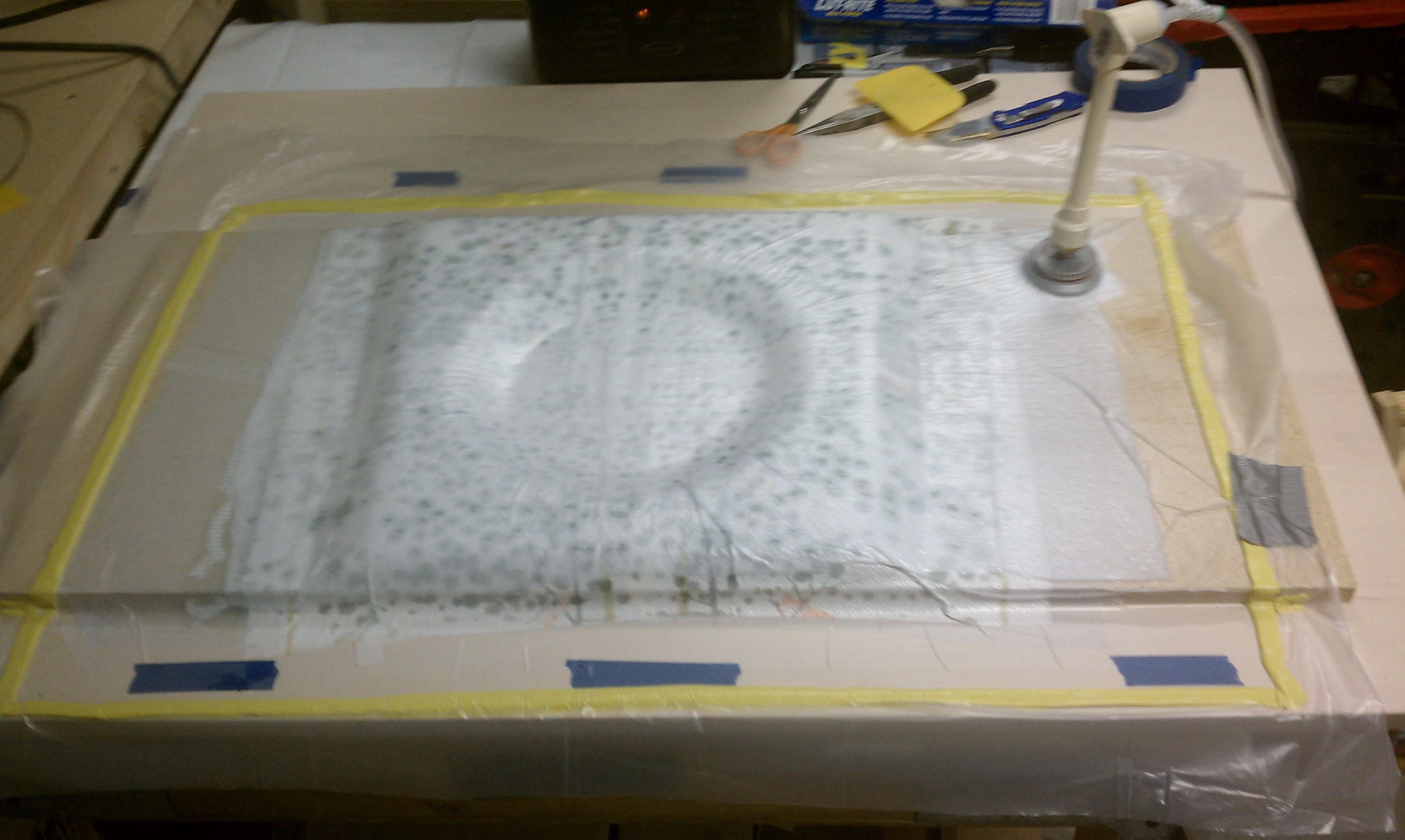
Spots excess epoxy being sucked out of layup
__________________________________________________________________________________________________________
28 April 2011 — Here’s a shot of the rear seat bulkhead after the vacuum bagging materials were pulled off. I understand there is wax paper in the vicinity, and that I will burn in hell for using it, but honestly that’s what we were taught in our EAA composites course. After being soundly thrashed by a few seasoned Canardians, I stopped the heinous practice of using wax paper!

Rear seat after vacuum bagging
A shot of the two finished seat bulkheads: front & rear.

Done! Front & Rear Seat Bulkheads
•••
Chapter 4 — Step 3 of 4
30 April 2011 — I only have this one pic of glassing the instrument panel bulkhead. As you can see, I vacuum-bagged the instrument panel. Vacuum bagging really does suck out all the extra epoxy and produces a much lighter part.
•••
Chapter 4 — Steps 1-3
3 May 2011 — The F22 bulkhead before the leg holes were cut out and the F22, F28 and Instrument Panel Bulkheads.
F22 Bulkhead
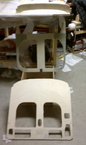
F28, F22 & Instrument Panel Bulkheads
___________________________________________________________________________________________________
12 June 2011 — Ok, obviously by just that fact that I’m building an “experimental” airplane I like to experiment, at least a bit. I thought quite a lot on how I wanted my instrument panel to look. I wasn’t sure exactly, but I figured I would make the top layer Carbon Fiber on the front face of the panel to A) Add stiffness and B) Add coolness. I ordered some CF in my last Aircraft Spruce order and after it came in, I assessed it one last time and decided to pull the trigger! ↓
•••
Chapter 4 — Step 4 of 4
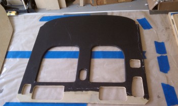
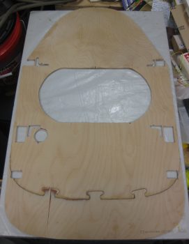
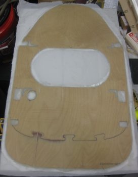
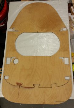
4 May 2011 — Firewall after cutting out of 1/4 in. Finnish Birch plywood:
11 June 2011 — After another few discussions with some experienced Canardians familiar with the old glory days of the Cafe Races, I decided on another modification. Now I’m sure this may very well elicit some groans and ha-rumphs, and maybe even a few mutterings of how crazy I am, to put it politely, but I decided I was going pulley-less and running my rudder cables from Point-A (the rudder pedals) through a curved conduit that traverses through the centersection spar, makes a semi-shallow bend and heads to Point B (the rudders). No fiberglass strands will be hurt in the making of this modification, just merely slightly separated at the holes in the foam so that glass strength and integrity is still in tact on the centersection spar. So, no pulleys means that I don’t require the pulley brackets, and thus no “ears” on the firewall.
BACK UPDATE: I had ordered my Carbon Fiber cowlings from Feather Lite, but with a twist: Mike & Larry were going to put a joggle down the center of top and bottom of the cowling so that I could adjust the cowling widths to my new wider fuselage. Unfortunately, as they played around with the original plugs and molds— [these were the exact same molds that Mike Melvill designed for his armpit scoop cooling design that he installed before his round-the-world trip with Dick Rutan] —they realized that it was just too problematic and difficult to put the joggles down the center of the cowling halves. Plus, it would add significantly more weight, minimizing the benefits and increasing the cost, thus nearly negating the reasons for using CF on the cowlings to begin with.
Thus, I would have to go with the original cowling size, meaning I had to trim my firewall down to it’s original plan-sized dimensions. Of course, the firewall being back to its original size does nothing for me if I can’t mount it to my top & bottom longerons… which was the case since my rear seat was widened by 1.2 inches. So I recalculated everything, and not wanting to have go after my front seat (read: cut) I compromised (the art of engineering, eh?) and narrowed my existing modified rear seat back by 0.4″ to only 0.8″ over stock. Which still is a decent amount of extra room in this narrow of a cockpit.
The one effect it did have was that it accentuated the curve of my cockpit to make it even more football shaped (fatter at the center, and narrower at the ends). I’m not an aerodynamicist, but I have had some folks say that my shape is less desirable and less efficient than the original design. Regardless, I think it will still fly even with a potential small increased drag penalty.
Once I finished cutting the ears off the firewall, I could get to glassing it (and laying up CF on the instrument panel).
•••
28 October 2016 — Today was kind of a slow build day, but I did get a couple of things knocked off the list: I backtracked to finish a step in Chapter 4 that is about 5 years late in the making: glassing the front face of the firewall with 1 ply of BID. I had held off initially to wait to see if I needed to added any screws, etc. and just never got around to glassing it.
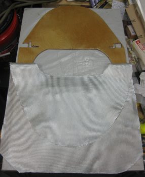
I used the firewall as a template to mark & cut the BID at a 45° bias.
I then took the firewall outside and sanded it down with a DA sander to prep it for glass.
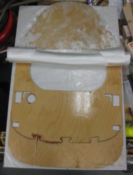
I set the BID in place on the firewall then pulled it down and wet out just the top side of the firewall face.
Then I set the BID in place on the top side of the firewall, rolled the BID up towards the top and wetted out the bottom of the firewall face with epoxy.
I then wet out the entire BID on the firewall face.
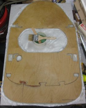
With the BID wetted out on the face of the firewall, I then peel plied the entire layup.
•••
29 October 2016 — Today I spent a good half hour between removing the peel ply off the firewall front face 1-ply BID layup and then razor trimming the edges. The firewall looks good and is very close to getting mounted. I do have to do some minor sanding along the edges and a couple places on the front face, and quite a bit on the aft side since I didn’t peel ply it for some odd reason (that was back in 2011, so my memory is foggy on why I didn’t peel ply it! . . . )
•••