
Chapter 14 – Centersection Spar: Final Steps
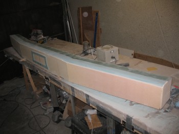
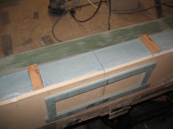
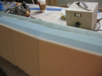
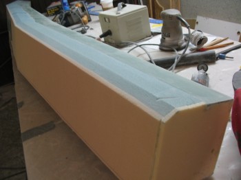
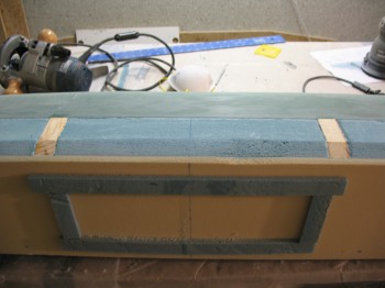
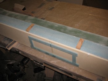
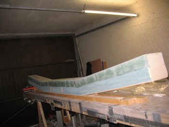
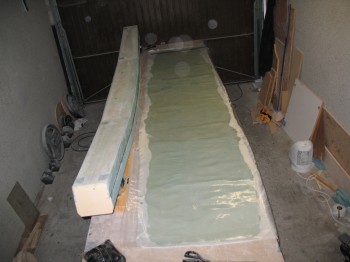
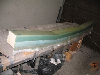
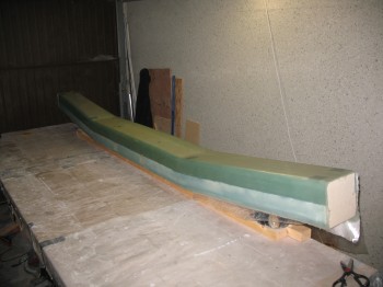
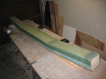
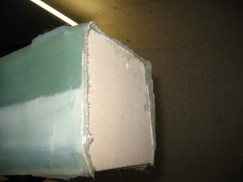
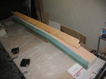
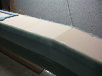
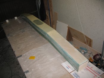
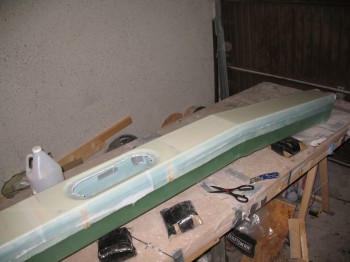
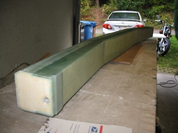
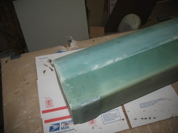
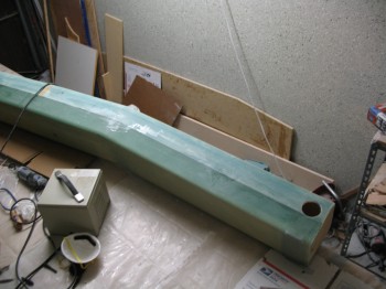
13 September 2012 — Since sanding is so fun, I continued on in my material removal quest by starting in on removing the front corner wedge. This wedge is removed to create an angled corner “LE” on both the top & bottom that will eventually receive the also-angled glassed foam top & bottom skins of the strake. In fact, the front Outboard faces of the CS spar makes up the aft wall of the fuel tanks and are forever hidden (hopefully) within the strakes once everything is all glassed up.
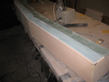
I’ve mentioned it before, but it’s amusing to me how a number of steps spelled out in the plans look so benign, simple and minimal in effort . . . until you start the step. These front corner angles look simple enough to remove the material, but it took quite a while and a fair amount of work. It probably didn’t help that I used the much tougher blue PVC vs the easily-carved Urethane foam in my construction of the CS spar. Even still, I’m happy with my choice to use the blue foam.
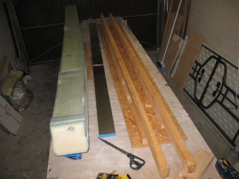
I took a break from shaping the corner angles & grabbed my Spruce wood hard points that get embedded into the CS spar for the engine mounts to bolt to, as well as the fuselage longerons. I had cut those hard point inserts a while ago, so installing them was simply a matter of marking & removing the foam from the hard point locations.
Also, a week or so ago on a slow build night, I had measured out the new locations of my hard points compared to the stock plans location since my fuselage is wider. And, although my fuselage is wider, so too are my longerons. Thus, my hard point locations were only about .2″ off from the original plans location.
•••
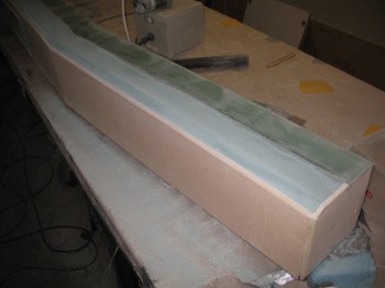
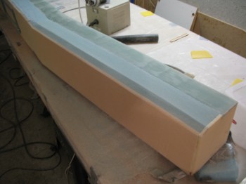
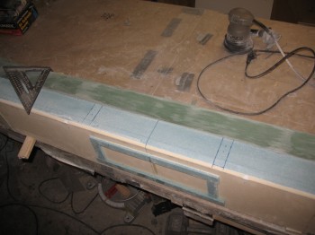
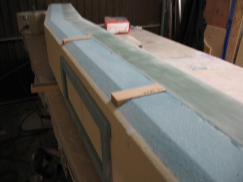
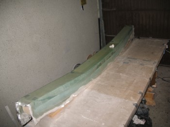
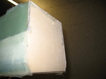
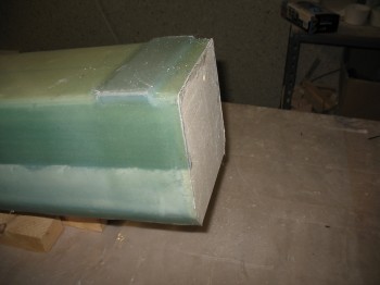
14 September 2012 — I used a coping saw to cut off the remainder of the 1/2″ x 1″ wedge-shaped angle on the front corner of the CS spar. I then sanded to shape the angle on the front corner to finish it.
I shaved just hair off the length of the top Spruce wood hard points so that they were just under 3″ in length.
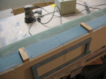
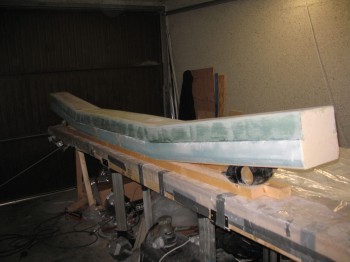
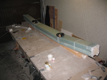
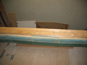
After I mocked up the Spruce hard points for a good trial fit on the spar top side, I flipped the CS spar and belt sanded the spar cap “steps” to smooth out the spar cap surface. I also hit the bottom spar cap with the orbital sander just to smooth it out a touch more. I then sanded the foam of the bottom side just in front of the spar cap to match the foam & spar cap to each other & smooth out the entire bottom spar surface.
I Dremeled all along the joint between the spar cap & the foam on both the top & bottom side of the spar, down the entire length of the spar caps to remove dead micro, flox, epoxy & glass.
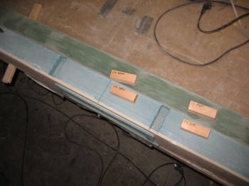
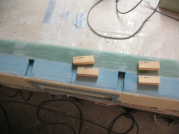
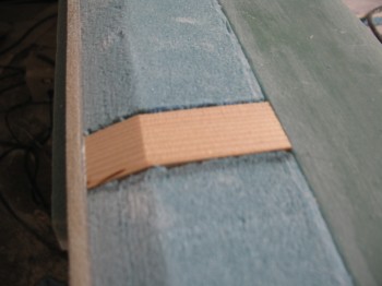
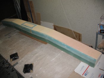
I made a trial fit of the Spruce hard points on the bottom side of the spar after marking, cutting out & removing the foam. I trimmed the bottom Spruce hard point blocks by almost 0.1″ in height to allow room for the micro that would be used to bond them in place. I then mitered the angle on the front of each Spruce hard point to match the angle on the spar face foam.
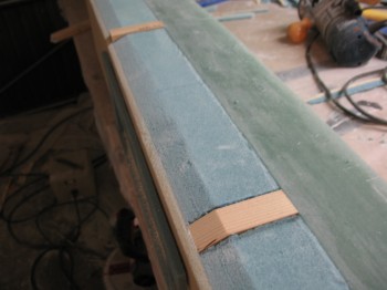
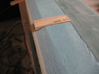
After all the prep was complete, I micro’d in the 2 bottom Spruce hard points.
I then cut the 4 layers of UNI for the final wrap of the top, bottom & back faces of the CS spar (layup #6). The front face of the spar is left to glass until last and accounts for the access hole in the front of the spar and also overlaps onto layup #6.
•••
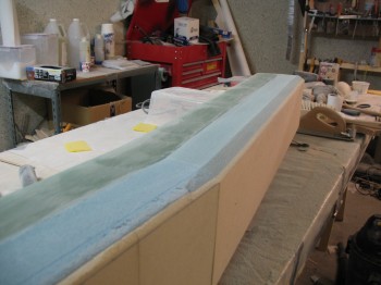
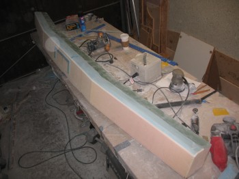
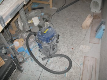
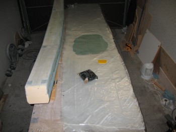
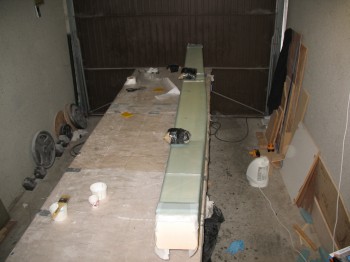
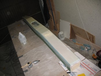
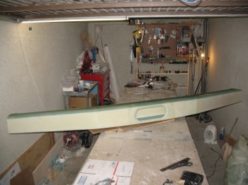
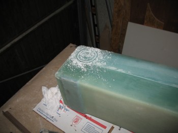
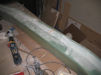
21 September 2012 — Today I started by cleaning the shop. As you can see the sanding to knock down the steps and get the spar surface smooth has left the shop a complete fiberglass & foam dusted mess.
After I got the shop cleaned up, I measured, cut, fitted & micro’d the top 2 Spruce wood hard points.
I also sanded the spar cap corners so they would be radiused when it was time to glass the spar skin.
After the micro cured, I cleaned up & Dremeled the edges of the Spruce hard points top & bottom to clear out any wayward micro, etc.
•••
24 September 2012 — Today I cut 2 sets of the Outboard UNI extrusion caps: 3″ wide x 12″, 14″, 16″ long.
I also cut 2 sets of the Inboard UNI extrusion caps: 3″ wide x 8″, 10″, 12″ long.
Finally, I cut 2 sets of BID for the final Outboard extrusion layup glass ply (5″ x 6″) and 2 sets for the final Inboard extrusion layup glass ply (5″ x 8″).
•••
25 September 2012 — I set up the heaters today to get the garage/workshop ready for the big layup #6 glassing, but I couldn’t get it heated past 62°F.
So I pre-deployed the cut glass to the garage & decided to wait until Saturday to do the big layup (so I could do during the day while the weather is obviously the warmest).
•••
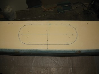
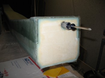
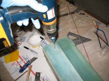
29 September 2012 — I started off today by mounting two long 2×4’s to the middle of the 5″ x 14″ oval access panel.
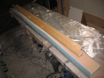
I used 3″ long drywall screws & the nice part is that it’s drilled to glass that will simply get removed and chucked.
I laid out the plies of UNI & cut plastic for the pre-preg.
I micro’d the foam with both dry micro & microslurry. I then wet out the pre-pregged UNI.
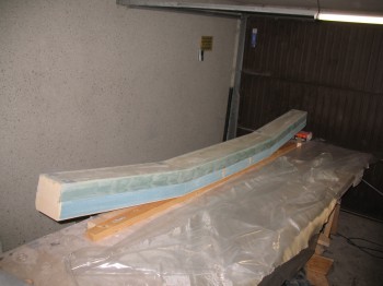
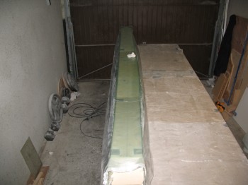
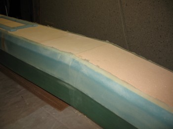
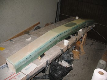
I then laid up the pre-pregged UNI glass onto 3 sides of the spar: top, aft & bottom. This is the plan’s Layup #6.
I cut the edges on each side close to the 1/2″ x 1″ wedge cutouts on the front corners of the spar.
I then floxed 2 each LWA3 aluminum extrusions & 2 each LWA3 aluminum extrusions on top of the existing Inboard & Outboard extrusions. I covered the LWAs with the UNI & BID plies that I cut on 24 Sep.
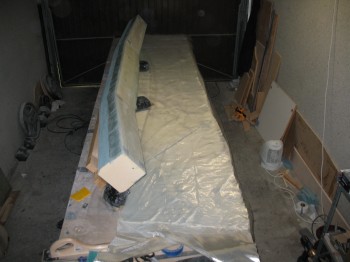
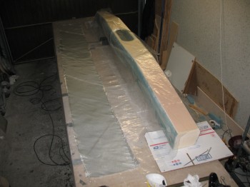
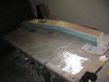
I then peel plied the entire layup & weighed down the Inboard extrusions.
•••
30 September 2012 — I started today by refilling the slow hardener bottles & cleaning the Dritz scissors.
I then removed the peel ply from the CS spar, cleaned up & removed the peel ply strings & goobers from the layup.
I used the Fein saw to cut the glass flush at the CS spar end.
After cleaning up the end glass on the spar, I removed it from its 2×4 mounts.
I again used the Fein saw to trim the glass along the top & bottom edges (at the angled/wedged corner) so it was close to the foam. I hit the edges with a hard sanding block as well.
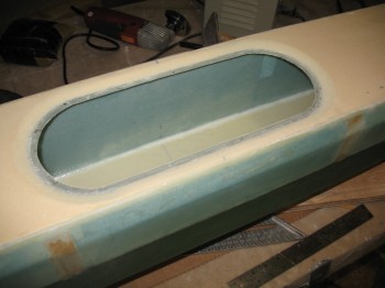
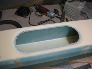
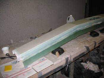
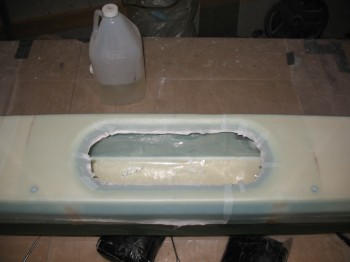
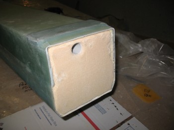
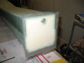
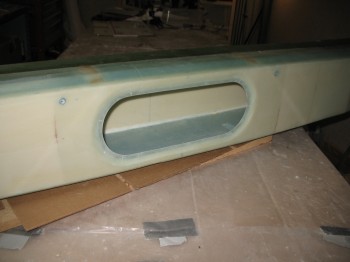
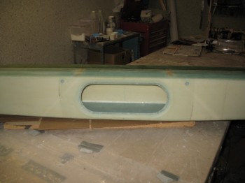
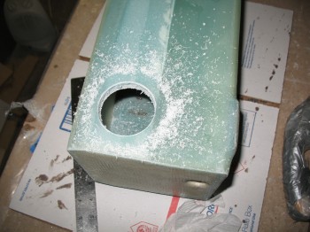
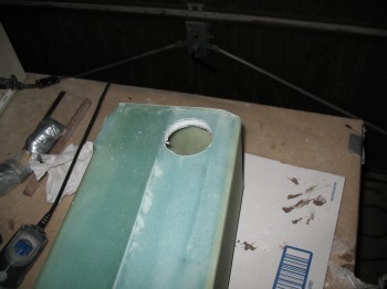
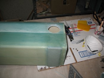
I cut the 5″ x 14″ oval access hole on the front face of the CS spar.
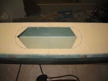

I removed the peel ply at the edge of the oval hole & sanded a beveled transition around the cutout.
I then sanded the entire front face & Dremeled out any dead micro & epoxy.
Finally, I vacuumed the entire spar & the surrounding work bench.
•••
1 October 2012 — I started off today by refilling some more hardener & consumables.
I cut 11-1/2″ wide UNI strips across the full length of the roll at 45° . . . enough for a 2-ply layup across the front face of the CS spar. I also cut an 11″ x 22″ 1-ply BID piece at a 45° bias for reinforcement around the center spar access hole.
I had a couple delams right along the edge of the angled/wedge corner … apparently I didn’t squeegee it well enough and gravity did it’s work & it separated just a hair. I quickly gave it an injection of epoxy.
I used a flox/micro mix for the edge & edge divots. I also added some flox around the edge of the hole as a base layer since the glass was thin but still a bit rough from how it had cured before.
I glassed Layup #8 (2-ply UNI ± 45° … so 90° angle to each other). As I laid up the glass, I very carefully separated the glass fibers around the holes for the rudder cable conduit, just as I had done with the glass on the back of the spar.
I glassed the 1-ply BID around the the oval access hole & then peel plied the entire layup.
•••
2 October 2012 — Today I started by using the Fein saw (again, I call it that for ID purposes, but mine is actually a cheapo version from Harbor Freight… but it works great!) to remove the overhanging glass on each end of the spar & on the straight runs of the oval access hole.
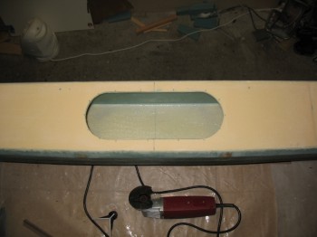
I then focused on the oval access hole with the Dremel tool. I knife trimmed it as well to remove all the excess/overhanging glass. I also used my Perma-Grit tool and sandpaper to smooth out the access hole edge and surrounding glass.
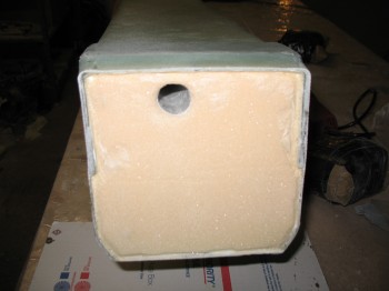
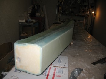
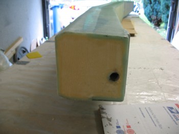
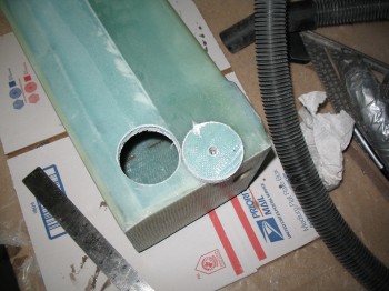
I used a 7/8″ bit to drill out the foam covering the electrical wire/antenna cable conduit at each end of the spar. I sanded it to round over the edge of the hole for a nice radius.
I then Dremeled out a narrow wedged-shaped channel into the foam at each end of the spar around the inside edges of the glass. I removed the foam on the inside of the glass to maybe 1/4″ deep max.
I sanded the foam faces at each end of the spar, vacuumed the end bulkhead surfaces & prepped for glass.
First, I cut 2 pieces of 7.5″ x 7.5″ of BID at a 45° bias.
Then I floxed the edges of the glass into the channels I had just created in the foam. What this does is create a fillet in the corner between the existing 4 sides of the glass & the newly laid glass. Once it cures, there will be a very solid “triangular” (as best possible) corner bead that will greatly increase the strength of the corner, and also the bulkhead’s glass ply covering.
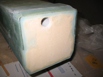
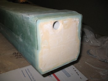
I micro’d the remaining foam in the middle of the end bulkheads. I then wet out the pre-pregged 1-ply of BID…. which is hard to see with only one ply. I then glassed each end of the spar with the 1-ply BID pre-pregged layup.
I trimmed the excess glass with my Dritz scissors (still awesome!) & then made an X-cut in the glass over the hole and plugged each one so the glass would wrap around the radiused edge of the hole and cure securely onto the interior of the channel conduit.
•••
3 October 2012 — Today I started by knife trimming all the edges that needed it, including the newly glassed end bulkheads.
I also sanded down all the edges that required it & removed peel ply boogers.
•••
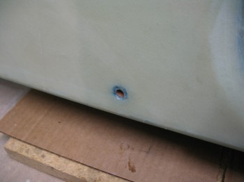
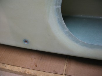
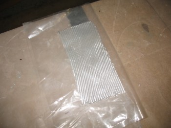
5 October 2012 — I started off today by installing & floxing into place the phenolic tubing that will be the conduit for the Nylaflow rudder cable conduit as it traverses the CS spar front & aft walls.

Again, I’d like to reiterate that these holes were created in the glass layups on both the inside & outside walls by carefully separating the glass fibers so that they went AROUND the holes. No glass (or shall I saw the minutest amount) was cut or drilled to install this phenolic tubing.
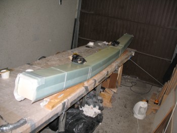
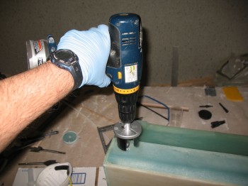
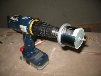
I then measured out & drilled a 2-1/4″ hole (approximately, I was using German hole saw bits so it was ~57mm) on each end of the spar on the bottom to allow access to the wing spar bolts.
After I drilled the holes, I Dremeled out the foam just a bit along the edge of the holes, cleaned everything up, and then dry micro’d the edges of each hole.
•••
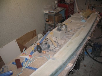
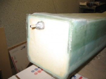
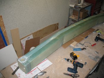
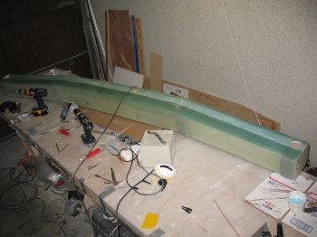
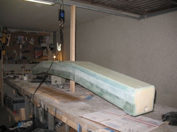
15 October 2012 — I started off today by lightly sanding the CS spar to remove all the excess epoxy that was all over the outer skin of the spar from the various layups & me handling it with sticky gloves at times.
Once I finished sanding it, I vacuumed the entire spar, inside & out.
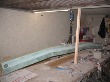
I threw a piece of scrap wood in as a support strut underneath the garage door crossbar & then attached a hanging “fish” scale to weigh the spar.
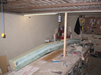
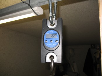
Mike Melvill, in CP 25 (maybe 26?) listed out the weights of his Long-EZ components. His CS spar was 29.5 lbs. So my spar is about 2.5 lbs heavier than his. Not bad, especially since I used the heavier blue foam. But I did use the new UNI layup as well, so it should have probably equalled out. Oh well, one thing I definitely didn’t have helping me out were the Aliens that obviously he, Burt & Dick had helping them out! . . . ‘cuz their low build weights are definitely alien to me! yuk, yuk!
I’ll comfort myself with a quote that is oft heard in the US military, and oddly enough was actually credited to Soviet Admiral Sergei Georgievich Gorshkov:
“Perfect is the enemy of good enough”
(Yes, it’s come down to me quoting Soviet Admirals to justify my shoddy workmanship! Ironic? Or just time for me to take a break from building?! ha!)
•••
25 April 2013 — Today I had to go pick up some more items at the BX on base & Praktiker to prep for the canard build.
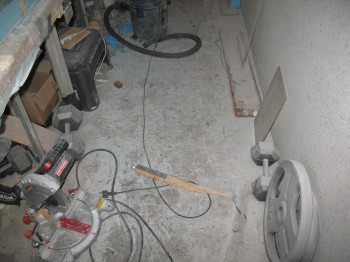
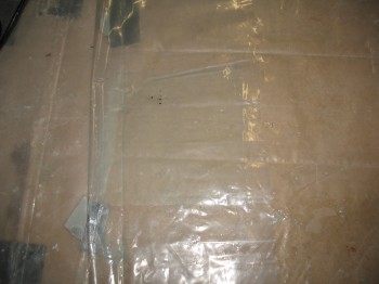
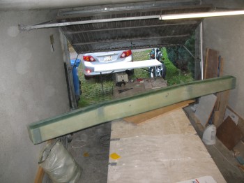
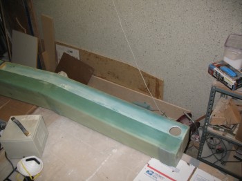
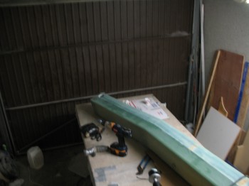
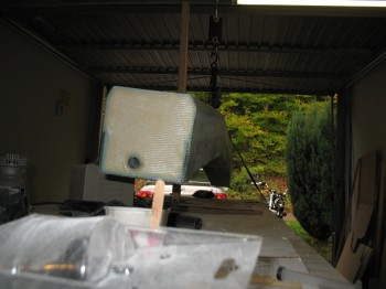
It had been over 6 months since I stepped foot into my garage workshop, and this was what it looked like:
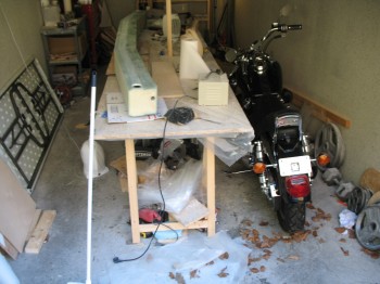
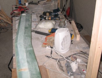
I was in a mad dash when I left here trying to get on with my deployment to Tampa, so I took a fair amount of time cleaning up the garage work shop to get it back into build shape.
My first order of business was glassing in the 1-ply BID corner tapes at the corner junction between the interior bulkheads and the interior surface of the front face of the spar. The CS spar is of course a torque box in many respects, so it’s made to carry & handle twisting and other various loads, so I’m not trying to make these corners solid immovable forces, I just want to add another solid attach point to the front face of the spar, which is merely bonded on via micro to the foam edges of the top & bottom surfaces. To be sure, there’s glass that wraps around the outside of it, but there’s no interior glass-to-glass attachment along the interior front face of the spar.
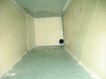
This is an interior shot looking towards the right side of the spar. The inside front face of the spar is to the left.
← Front
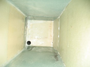
This is an interior shot looking towards the left side of the spar. The inside front face of the spar is to the right.
Front →
Again, the goal here is to glass a 1-ply BID tape layup into the corner of the bulkhead and front interior face (opposite the antenna & electrical cable conduit hole). Also, this is not per plans. Adding these two 1-ply BID corner tapes is an additional mod to the plans.
I cut 2 pieces of BID, set them up into 1-ply BID pre-pregs. I then started by filleting the corners with a small amount of micro, that had just a dash of flox and Cab-o-sil mixed in to give it some umph.
The actual order went along like this: I mixed the micro first, holding back some epoxy to wet out the pre-preg setups. Once the micro was ready to go, I wet out the 2 separate plies of pre-pregged BID. Then I filleted the corners, with my 1-ply BID tapes at the ready once the filets were in place.
Now, the challenging part of all this was that I couldn’t see anything that I was doing. These two layups were done completely in the blind & only by feel, having to reach my arm way up into the interior of the spar on each side. One of the reasons I had the camera on hand was to use it to check my work.
I laid up a 1-1/4″ x 5-1/4″ 1-ply BID tape into each corner on the left & right side of the spar.
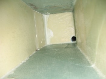
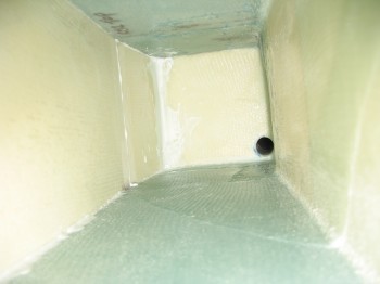
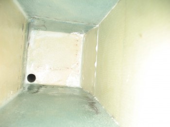
The first two pics above show the right side corner BID tape, while the pic immediately above shows the left side corner BID tape.
Once the interior corner BID tape layups were glassed, I set the spar aside and started building the jig for the Roncz Canard build.
•••