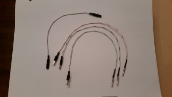
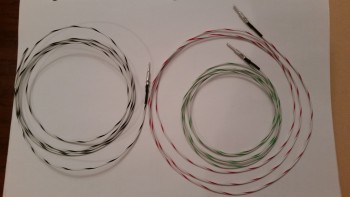
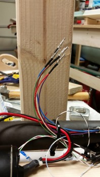
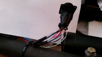
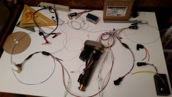
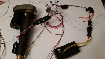
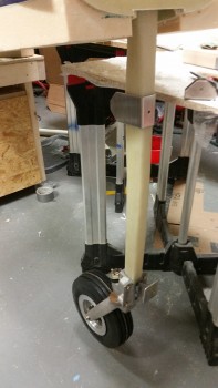
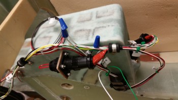
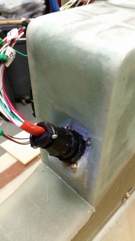
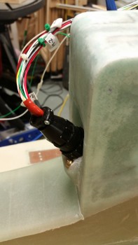
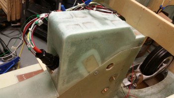
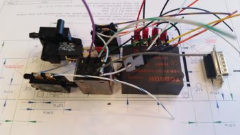
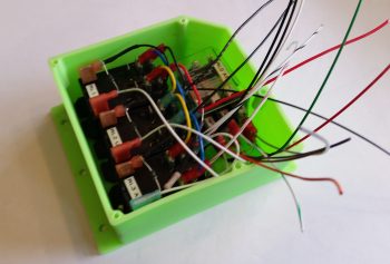
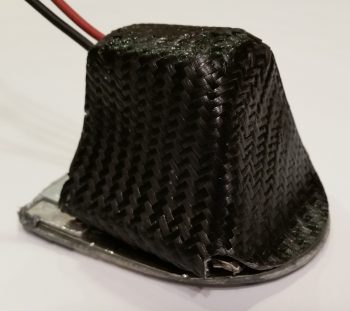
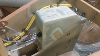
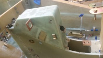
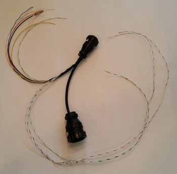
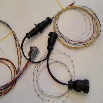
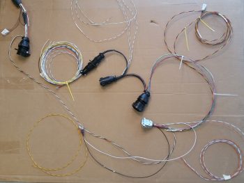
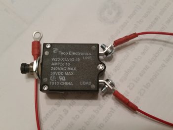
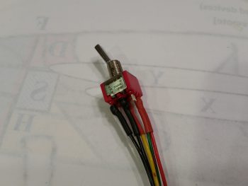
Nose & Nose Gear Wiring
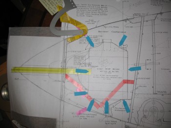
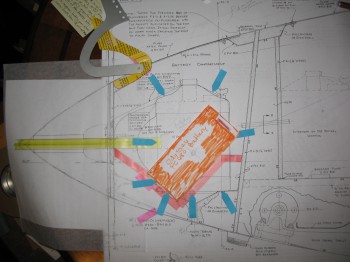
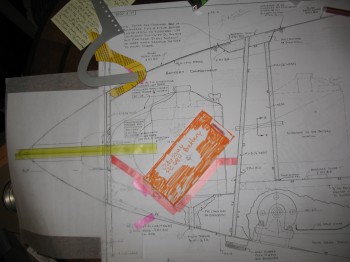
19 May 2013 — Today I decided to act on yesterday’s vow to figure out my build plan for the Davenport extended nose. I broke out the Davenport extended nose plans, figured out a myriad of details and made a template for my NG-30s.
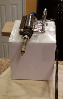
One thing in specific I was looking at was the battery position & its installation configuration in relation to the heated pitot tube, and how it effected the capability of retracting the pitot tube.
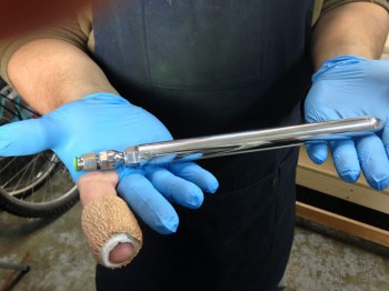
Now, let me backtrack to February 2013. I may have been a little remiss in the reporting of my project progress since I overlooked an extremely important component: my retractable heated pitot tube made for me by my good friend Marco, a fellow Canardian and Long-EZ builder . . .
Yes, Marco–being the excellent & talented machinist that he is–machined me this beautiful retractable heated pitot tube. Of course this wasn’t just a simple ‘throw some metal on the lathe and here it is’ endeavor, it took literally a couple months of research and discussion, and quite a bit of engineering and design. And countless hours of machining work by Marco. Marco describes the first part of the process here on his Blog What have I gotten myself into!
In addition, Marco covers the features of my Pitot Tube in this awesome video he made:
•••
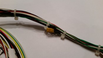
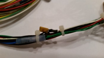
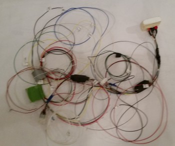
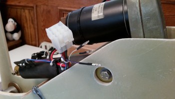
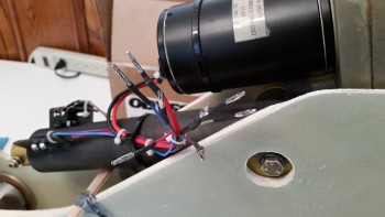
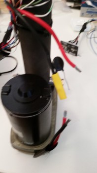
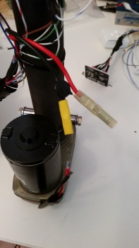
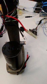
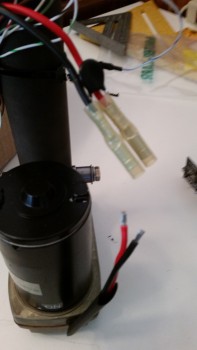
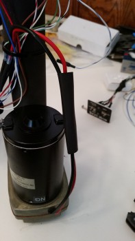
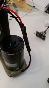
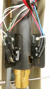
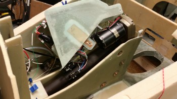
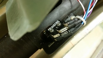
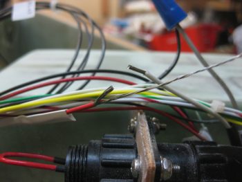
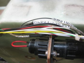
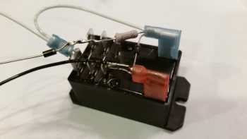
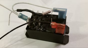
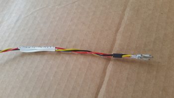
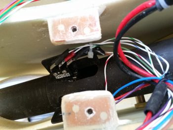
27 October 2015 — I sat down to fix a design flaw in the Nose Gear Actuator wiring before it became a problem. There is a small electrical component (diode? capacitor?) that was soldered in the wiring line with one of its two tiny legs soldered to a wire on each side. If you look at the second pic you can see daylight between the component and the wiring bundle.
Now, my Long-EZ building buddy, Capt Meatballs, pointed this out to me after his broke and he had to find it via troubleshooting. The connection legs were so fine, that when the one side broke he had to buy an entire new component & solder back into place to fix it.
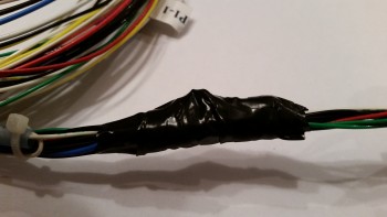
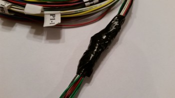
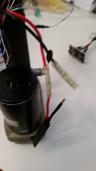
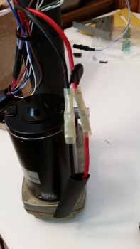
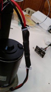
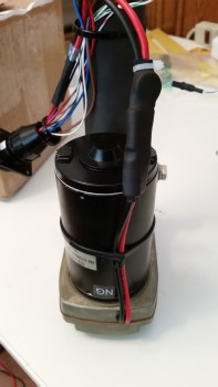
To avoid this issue I employed the “poor man’s electrical potting material” solution to this situation. I took electrical tape that I had folded over a couple of times and wedged it underneath the suspended wire legs on each side to secure them from any pressure coming through the tape and still snapping off one or both of the legs. I then wrapped the whole assembly in electrical tape. May not be the prettiest fix, but with a big clump of relays just down the line I wasn’t able to get some tubing shrink wrap over it. So this fix will have to suffice!
Now that I have the base of the fuselage dolly built, I’ll start incorporating it into the build schedule. Thus, while any part, epoxy, or primer is curing I’ll take a few moments to get this dolly built. My plan is that when I start in seriously on the nose & nose gear that I’ll have this fuselage dolly underneath the fuselage and ready to go.
•••
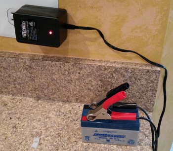
28 October 2015 — I grabbed a battery tender from the garage & put the small emergency back-up battery for the nose gear on a trickle charge to get it ready to go when I eventually wire up the nose gear to test it out.
•••
2 November 2015 — I spent the first half hour this morning finalizing my wire tracking & matching endeavor on the EZ Noselift Actuator wiring harness. I got down to 2 unclaimed wires, but wasn’t sure & couldn’t tell by the wiring diagram if they were supposed to be spliced together, although I suspected they were.
I fired off a quick e-mail to Jack Wilhelmson to verify a few things on the wiring and he e-mailed back shortly later to set me on the straight & narrow path! So all is good thus far in the wiring department for the nose gear actuator.
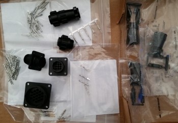
After I got everything straight with Jack, and as I was waiting for his e-mail, I was finishing up some research on Amp CPC connectors on Mouser.com. I ended up calling Mouser to confirm that I was ordering the correct stuff. After cracking the code on the various pins & sockets for the Amp connectors, I fired off my dorder to Mouser for Amp connectors to replace the Molex connectors currently used in the nose lift actuator system.
•••
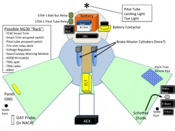
7 November 2015 — Today was about research and getting reacquainted with my electrical system. My specific interest was in figuring out what components, electrical & otherwise, that I was going to put into the nose.
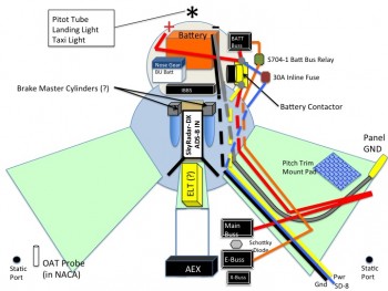
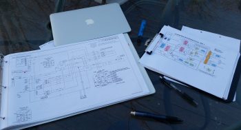
Now I know a lot of my contemporary building buddies would whip up some awesome looking CAD diagram with exact dimensions down to 3 decimal places that looks like an engineer’s dream, but me being a former military “Powerpoint Ranger” and certified neanderthal, I simply added a slide depicting my thoughts on this matter onto the end of my ongoing notes for the nose build.
Again, this stuff is really just a mental thought jogger on what will most likely go into what areas in the nose, and get me thinking if there is any pre-actions or prep I can do as I build the nose. Some of the components I ID’d will be in the nose area, but aft of F22: OAT probe, static ports, buss fuse housings, etc. In addition, on many of the components I had to look up in my notes, emails, websites, install manuals, etc. to either confirm or research further why and how they were getting installed where.
Now, I mentioned CAD earlier, so speaking of CAD: The CAD program I was using to create my electrical diagrams was NanoCAD, as recommended by Bob Nuckolls in the AeroElectric Connection online forum. This was a great CAD program for electrical diagrams primarily because A) it was what Bob used to create all of them, and B) it was FREE! Unfortunately, my version of NanoCAD is no longer supported and apparently NanoCAD is now on Version 7, which costs a decent amount of money now to buy.
Well, no worries since I have TurboCAD, which I happened to purchase while I was in Tampa, Florida. But I didn’t have it loaded up on my desktop so I ended up spending a good half hour loading up TurboCAD and familiarizing myself with its features before I could open up any of my electrical diagrams. Why? Well, in a series of typical events, I had taken all the hardcopy printouts of my electrical diagrams down to my buddy Marco’s house while I was on leave from Qatar in March 2014, forgot them there, and haven’t been back to retrieve them yet . . . mainly because every time I go to visit him he puts me to work building HIS Long-EZ! HA! (Click here for the real story . . . )
Thus, to be able to make my annotations on my electrical diagrams on an actual sheet of paper, I had to be able to open the darn files to print them, which I am happy to report that I am now able to do.
In line with my reviewing my nose electrical components, my main preparation is in getting the nose gear actuator wiring sorted out to test it. I had planned on going over all my electrical stuff today since the epoxy was still curing on the canard and also, in part, because my AMP CPC connector order from Mouser was scheduled to be delivered today, which it was.
I checked out all the goodies from Mouser and pretty much solidified my plan for the wiring & connections for the nose gear actuator system.
Next I plan on wiring up the nose gear actuator & testing it out.
•••
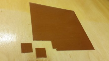
8 November 2015 — Today I cut out the 2 phenolic support pieces that will be embedded in the NG30 cover for the AMP CPC connectors.
•••
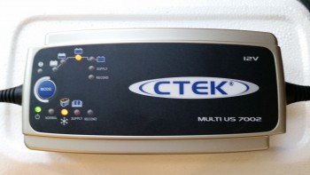
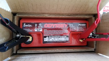
11 November 2015 — Today the UPS guy showed up with the battery charger I ordered from Amazon last week. I ordered this battery charger because in reading the manual for the Odyssey PC680 battery it stated that if the battery charge fell below 12.65 volts, than it needed to be charged before using it. When I checked the battery, the multimeter showed 12.57 volts, clearly below the threshold required to be able to use the battery as per the instructions.
Of course I knew I would need a battery charger eventually since the Odyssey PC680 is an Absorbed Glass Mat (AGM) type that is immune from acid spills and gas venting, and thus has some unique charging requirements to ensure the battery is maintained in an optimized state before it’s actual use in the Long-EZ. An interesting side note to this battery is that it can be mounted in any position.
Currently, the main reason I want to use the battery is to test the nose gear actuator. So when the battery voltage tested low I checked the Odyssey website for approved battery chargers. After assessing a few battery chargers online, I decided on this one and ordered it.
I hooked up the battery to the new charger before heading out to a meeting I had at the office. Before I left for my meeting I went upstairs and changed clothes –about 5 minutes– and when I did a final check before walking out the door the charger had already completed its first 2 phases and was in the basic charging phase. This was a good sign since the initial phases are conditioning cycles that bring a battery back to the point where it can simply be charged in phase 3, where again, my battery was before I even left the house. By the time I returned about 2 hours later, the battery was fully charged and was at 13.87 volts. Not bad!
I’m discussing the battery at this point since the short term use of the battery is to test the nose gear actuator (Chapter 13) while of course the long term use will simply be as the aircraft’s primary power source (Chapter 22).
•••
13 November 2015 — Today I worked on the nose gear actuator wiring.
My first task was to pull off the motor side Molex connector, since I’ll be replacing it with an AMP CPC connector.
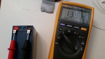
I then double-checked the charge on my nose gear back-up battery. At 13.11V it looked good and seems to be holding its charge well.
While tracing out & connecting the wires for the nose gear actuator I was able to integrate & plan out the wiring for the gear & canopy warning module. Basically, I figured out that I can use the up & down limiter “micro-switches” on the nose gear actuator to drive the warning signals to my gear/canopy warning module. Of course the only issue is that I’ll need to order another AMP CPC connector. No worries really, since I was going to have to do some finagling with the thick power wires to get them into the 9-pin AMP CPC connector. A larger connector will be able to accommodate bigger wires.
•••
15 November 2015 — Today I ended up working on the electrical system for about a total of 6 hours.
Although I didn’t add it to my log entry, I had actually spent a couple of hours Saturday diagraming out the circuit for my canopy & gear warning module. I thought I was looking for a DPDT microswitch to match the one Jack had mounted on one side of the gear actuator housing for the down limiter. The other side only has a single switch. I even sent Jack an email asking for the part number, since all the info for the microswitches were hidden from me on account of how they were mounted with the nomenclature, etc. facing the mounting flange. I didn’t want to move these suckers unless absolutely necessary since they’re “factory” set initially for the correct up & down limits.
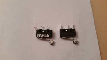
Well, right before I left the house for the evening I took a much closer look to see what type of roller the microswitch had and the length of the lever arm. Upon closer inspection I realize it had two rollers?? Wait a minute! This wasn’t one switch! It was two switches stacked one over the other! Doh! I remembered I had a microswitch included in my accessories for the speed brake, which I also bought from Jack. I pulled that switch out, saw that it was the same switch as those mounted on the nose gear actuator, and so was able to get the manufacturer and part number off of that one. I then quickly sent Jack an email saying that I apparently need glasses and to disregard previous transmission! All of this hassle for a $3 switch! BTW, the switch is an Omron SS-10GL2T.
With the switch issue settled yesterday, and with the added wiring the new switch circuit will add, I was armed with the info I needed to order a new 14-pin AMP CPC connector from Mouser. I assembled my order which included a whole lot more pins & sockets, a pin/socket removal tool and of course the Omron microswitches.
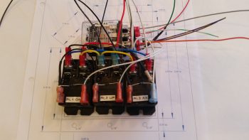
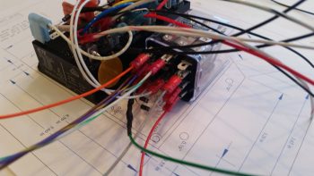
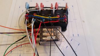
I then spent a few hours on virtually organizing the components of my electrical system. Yes, in true neanderthal fashion I pulled them all out, traced their profile on a sheet of graph paper, and then identified which bus they were wired to, and looked at the length & destinations of the wire runs. Again, since so much of this business occurs in the nose, and that’s what I’ll be building next, I don’t mind taking a few hours to get better educated on just what the nose will house before I start building it.
•••
20 November 2015 — I (finally!) went ahead and finished wiring up the nose gear actuator to test it out. You can see the test in the video below:
Getting closer!
•••
21 November 2015 — I mentioned that I had updated my electrical component placement plan for the nose. I finished the final mods this morning and figured I would post it for you all to see.
•••
27 November 2015 — Today I prepped a microswitch for mounting on the nose gear actuator as a part of the nose gear warning system.
I crimped up some 22 AWG wires for the nose gear warning system. These wires will be ran through the bigger AMP CPC connector that I recently ordered from Mouser.
These wires are also for the nose gear warning system, but they mount into the opposite side AMP CPC connector and will terminate at the gear & canopy warning module.
I also took the opportunity to re-terminate the socket connectors that come from the nose gear actuator side of the P1 connector.
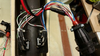
Here’s a shot of the P1 connector. After I confirm that all the connections are good I’ll zip tie the wires and permanently mount the cable clamp.
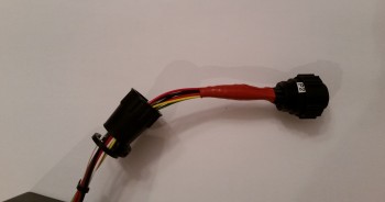
Also, the two power 12 AWG wires (Red & Black) coming from nose gear actuator motor in the end were just too big to fit into the back connector plate. I tried slightly expanding a couple of connector holes with a #29 drill bit to start out with, which worked well. In the end though, I finally threw in the towel and ended up chopping off the last 3″ of the power wires and replacing it with a 3″ piece of 14 AWG wire. You can see the connectors in the picture below where I spliced the new wires into place. After messing around with the unruly wires, it was great to work with wires that simply went where they’re supposed to!
•••
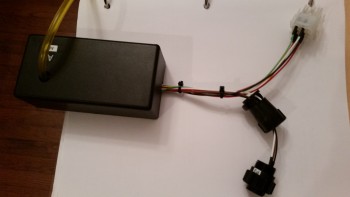
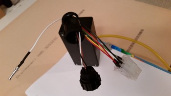
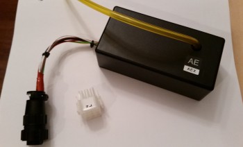
28 November 2015 — I worked on converting the P2 connector on the AEX from a 9-pin Molex to a 9-pin AMP CPC connector. Below are a couple of shots mid-mod.
I then wrapped the wires with self-amalgamating (“centerline”) tape.
And finalized the conversion by mounting the cable clamp.
•••
30 November 2015 — Today I worked on the nose gear electrical system to finalize the conversion of the connectors to AMP CPCs. I finalized converting the switch side (vs motor side) main connector P1 while concurrently cleaning up the wiring by zip tying the wiring. I also cut all the terminated wires to the same length.
Here’s a shot of the P1 connector (motor) and P2 connector (AEX) connected together.
•••
1 December 2015 — I had meetings and appointments today so I didn’t get back to work on the project until after 1700.
The first thing I did was to test out my new wiring connectors on the nose gear actuator. I double checked the connections, checked the battery voltage (12.86V) and then hit the switch. Ah, the motor came alive and down it went. Good deal. Then came the inevitable gotcha. I threw the switch the other direction to raise the actuator arm and heard . . . nothing. I double checked my wire connections, A → B, C → D, n → ∞, and all looked good.
So I tried it again. Nothing.
What ensued was about a 4 hour troubleshooting session where I did continuity checks on every single wire connection point, every run from starting terminal, through connectors, to the end connector and everything toned out perfectly on the Fluke. I checked the internal contacts from the P2 connector to the internal contacts on the AEX board. All good. I recharged the battery while I went out to the grocery store: fully charged at 13.23V, and still no up travel.
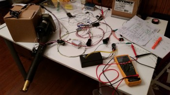
I reread Jack’s directions and happened upon a point of note about damaged microswitches. Since I now had extra I figured it wouldn’t hurt. When I started removing the microswitch on the right side facing the front of the unit, after marking its location of course, it literally crumbled in my hand. Not sure why that happened, but I replaced it. The good news is that I was able to reuse the lever arm from the newly deceased switch on the first switch body that got sucked into the ‘actuator of destruction’ and lost its lever arm. So I’m still down only one micro switch, but unfortunately the switch replacement still had no affect on the actuator being able to return to the up position.
Having exhausted every troubleshooting technique, and checking, double-checking and triple-checking every connection and continuity of wiring, I figured it was time to punt.
I’ll call Jack to figure this thing out.
•••
2 December 2015 —Later this evening Jack Wilhelmson returned my call. After telling him the symptoms, he diagnosed the problem as me mixing up some wires on the switch side of the AEX P2 connector. Sure enough, after we got off the phone I checked the wiring and had wired up the connector in the mirror image of how it was supposed to be.
Thinking that I had indeed found the problem, and then remedied it, I wired it all back up. It just so happened that the last step was to connect the AEX hot power wire to the battery. Well, when I did I was met with a distinct & resounding “POP” sound. Initially, I thought (and hoped) it was the 5-amp inline fuse that sounded off. But alas, it was something on the AEX board. I couldn’t see any physical damage but when I cracked the case I certainly could tell that I had let the smoke out of one the components by the smell.
Ok, so during our discussion Jack had told me that if no AEX unit is used then pins 5 & 6 on the P2 connector require a jumper across them. I disconnected the AEX and then rigged up a jumper across pins 5 & 6. I rechecked the rest of wiring, connected power and then hit the up switch.
Nothing.
It was late in the evening so I’d have to wait until the next day to give Jack a call back and confirm both the AEX status and how to fix the persistent issue with the nose gear actuator wiring.
•••
3 December 2015 — I think the following account should be titled, “The Anatomy of a Repair”
I had committed two grave sins in the wiring of the AEX P2 connector, one on each side. On the switch side I found pin 1, inserted that wire and then started filling in the wires per color from pin 1, first across and then down. The only problem was that my first direction was as it should be if I was looking on the FRONT of the connector face, versus the mirror image it should have been on the back plate of the connector. Ooops. Well, as I said yesterday, I caught that after my discussion with Jack and remedied it.
What I didn’t catch was the wiring mistake I made on the AEX side of the P2 plug. When I had original diagrammed out the connector pins for that side, I realized that I hadn’t made the diagram in the normal top row=1-3, middle row=4-6, bottom row=7-9 pattern. If you took the diagram and flipped it 180° from the upper right corner down to the lower left corner, that is what I ended with: column A= pins 1-3, column B= pins 4-6, column C=pins 7-9. Thus, when I wired it up (mistake #3 actually, since it was LATE at night) I had the mental picture of the initial diagram (left below) in my head, not the correct one (right below).
I got ahold of Jack later in the afternoon to figure out the wiring issue with the electrical nose gear actuator. With the AEX presumably Tango-Uniform, I thought that perhaps I needed another jumper on pin P2 along with pins 5 & 6. I wasn’t sure about the jumper situation due the fact that since I ordered the AEX with my initial order of the gear actuator, I never received a jumper plug.
After some discussion Jack told me that if P2 pins 5 & 6 jumpered wasn’t getting the nose gear actuator to go back up, then I should try a jumper across pins 1 & 4. Ok, I had the plan and was ready to execute. I got off the phone ready to throw a jumper across pins 1 & 4. Uh, the only problem was there was no pin 1. The switch side of the P2 connector has 9 pins, and pins 1 & 2 are empty!
I called Jack back a few minutes later and gave him my report. With that knowledge in hand, along with my trusty Fluke, Jack began to guide me through checking voltage readings from points A → B, X → R, etc. I checked the relays by holding them up to my ear as I flipped the switch and was pleased to hear an audible springy click. We checked the up-travel microswitch since this was the primary culprit: 12.86V on both sides. All good. Then I checked the main power wires going into the actuator motor. 12.86V on the red and .005V on the ground… all good.
We were both stumped and Jack concluded that it appeared that the motor was bad. The problem was that these motors are amazingly robust and have an extremely low failure rate. Jack asked me to locate the heat-shrinked power connectors inches from where they exit the motor housing. I did. He then asked me to give all the wires a good tug to make sure they were connected nice & snug. They weren’t. The wires closest to the motor came out with the slightest pull.
That, my dear friends, seemed to be the real issue.
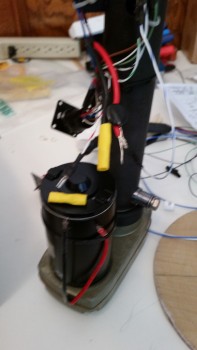
I asked Jack if I could run power straight to the motor with the inline fuse on the power side and he said yes. When I did, I was pleased to have the motor jump to life. Issue found!
(Thanks Jack, for such a great job talking me through the troubleshooting!)
[Note: Some of these pics are blurry since I’m using my phone camera … sorry. I guess phone cameras are made these days primarily for taking selfies to post on FaceBook!]
As you can see in the pic below, the yellow butt splice wire connectors are more automotive grade, which should have done the job ok, but for whatever reason here they didn’t.
Since the butt splice connector on the black wire was firmly in place, I started with replacing the one on the red wire. I was able to pull it off with a firm pull.
I then spliced on a higher grade butt splice connector that came in an electrical connector kit that I bought from B&C. You can tell the difference between the two immediately in the pic below.
With the red wire butt splice in place, I then pulled the old connector off the black wire and crimped a new butt splice connector in its place.
With the switch side completed, it was time to crimp the motor side wires into the butt splice connectors. I had already found an appropriate sized piece of heat shrink and slid it into place before completing the butt splicing.
I crimped the red wire butt splice first, and then finished with the black wire. It’s not easy to see in the pics, but the space that I had between the wires and the motor housing was fairly tight to get my crimper in place while still ensuring that the wires were fully seated into the butt splice connectors.
I pull tested all the wires to ensure they were securely crimped in place, then proceeded to cover my work with the good sized piece of heat shrink that I had pre-installed. I used my heat gun to shrink the heat shrink in place.
I secured both ends of the heat shrink with zip ties.
And then zip tied the newly spliced wires to the motor housing. As I was doing this the lower (in these pics) zip tie slid off the heat shrink so I simply cut it off.
Here’s a comparison of the butt splice connectors: old left, new right.
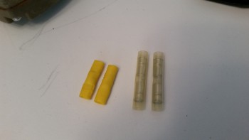
With my repair completed, I hooked up the wiring harness, sans the AEX and with a jumper wire in place between AEX P2 connector pins 5 & 6, and hit the switch.
Ahh, sweet success! The actuator motor came to life and up it went!
I reattached the gear strut in place to the NG8 pivot hard points on the NG30s.
Lastly, I installed the nose gear actuator into the NG30 nose gear box and wired it all up. I ran the gear up the first time I stopped it just below the F22 channel and then raised it a few bursts at a time. This was to ensure that A) the gear strut fit the F22 channel and cleared the sides, and B) the gear wasn’t going to crush the floor of the fuselage.
[Note: For specifics on the nose gear strut actuation, mechanical configurations, etc. please visit Chapter 13 – Nose & Nose Gear page].
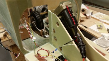
Although the gear troubleshooting was a real PITA, in hindsight I’m glad it all happened. Besides upgrading a critical failure point (apparently), I learned an immeasurable amount of information about my nose gear actuator system wiring. Instead of just barely getting through the wiring to get it to work and then moving on to the next task at hand (to be clear: I’m speaking about me here, and in no way mean this to slight other builders!), I feel like I have a really good solid working knowledge of the nose gear actuator wiring now.
•••
5 December 2015 — Today I made the requisite nose gear test video to make it official!
•••
6 December 2015 — I also spent about an hour doing some digging around online for information on my electrical system. Really, I was focusing on a lot of the little bits n’ pieces that will be required to finalize the mounting of various stuff in the nose area, such as Adel clamps, and hardware to mount those Adel clamps: screws, nuts, bolts, washers, etc.
I also ordered two different sizes of heat shrink tubing for my shrink wrap label maker. Now I have at least the first round of wire labeling for my wires ranging from 4AWG to 22 AWG.
I also updated my nose component diagram again and included it here.
•••
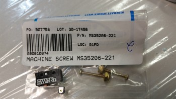
8 December 2015 — I set about today to add the second microswitch (for the gear up/down alarm) to the gear actuator housing. I pulled one of the screws from the current microswitch and when I went to put in a longer screw it was then that I realized that the set of screws I just ordered where the wrong size!
Here are the incorrect screws shown with the CORRECT microswitch. Well, it looks like there’s a bit more research in my future!
•••
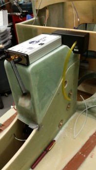
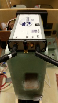
10 December 2015 — Today I mocked up the AEX module and the SkyRadar ADS-B receiver on the NG30 cover.
•••
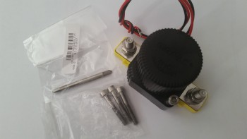
11 December 2015 — I thought I’d start out today showing a couple things I just received that will be used for the nose build. The first one is the shrink tube for making wire labels.
The other is the titanium metric M5 bolts and an M5 tap for mounting my battery contractor in the nose.
•••
12 December 2015 — Today I ran to a mom & pop neighborhood hardware store that my buddy Greg told me about during his Christmas tie project. Again, although I should have my order in hand from ACS on Monday, I wanted to get the gear up/down warning microswitch in place if possible. Well, I ran over to the hardware store and hit the mother load. Not only did they have the microswitch screws that I needed, but a lot more hardware for mounting the electrical connectors, etc.
Here’s a shot of the installed gear up/down microswitch! Yeah!!!
You may have noted that on one side the of AMP CPC connectors that I’m installing there’s a flange to mount the connector quasi-permanently to the whatever bracket, mount, etc. to which it will get mounted. I wanted to mount the P1 connector with the flange on the inside of the NG30 cover so that it could be removed by simply unscrewing the opposite half of the P1 connector, then removing the 4 screws to allow the connector to be removed. Otherwise I would have to literally remove the wire connectors from the backside of the connector housing.
However, to mount the connector in the way I wanted, I needed the connector mounting base with the phenolic insert to be thin enough to allow the outer side of the connector to screw on & lock into place. Since the angled mounting base was about 0.060″ too thick, it meant I had to get busy sanding it down on both the inside and outside. This took about 30 minutes all told, but I finally locked in the correct width.
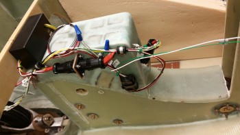
I then reinstalled the cover and mounted the P1 & P2 connectors into place. I also routed a bunch of the wires through a couple of mounted Adel clamps. I also mocked up the AEX to check its spacing. Admittedly, there’s still a lot of wires, but I’m really happy with the organization of all the wire runs. I’ll of course still continue to tweak these wiring configurations, but it’s a good starting point.
Since I’ll be sending the AEX back to Jack for repair in the next few days I made up a jumper plug for the AEX side of the P2 plug & installed it, as you can see in the pic below, so that I can run the actuator motor.
Here are a couple of shots of the installed P1 connector.
•••
13 December 2015 — Here’s another shot of the installed & wired NG30 Aft Nose cover.
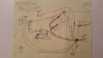
I also thought I would throw this up on the site before I threw it away. It’s my original chicken scratching diagram of the EZ Nose Lift nose gear wiring.
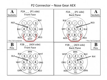
Finally, as for diagrams, I spent a few hours last night and a couple hours this morning making sure that I had my connector pins diagrammed out on paper. As of right now, I have about 7 AMP CPC connectors planned for use in my electrical system: the Infinity stick grips, throttle handle switches, etc. Each of those will have a pinout page depicting information on what wires are where & wire colors, and what connectors are being used, pins, sockets, notes and any pertinent info. Below is the first iteration of the P2 connector. Also, in addition to the P2 connector diagram, I finished the P1 diagram.
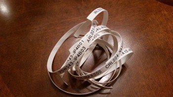
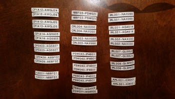
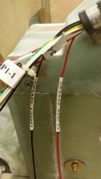
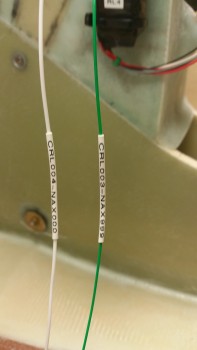
I took my list of wire label codes that I spent a couple hours last night researching & building to use to print out a bunch of wire labels. I’m fairly certain that I’ve already spelled out my code schema in detail here on this site, but after I work any wrinkles and kinks out of the system, I’ll touch base on my wiring code again.
In essence, I have two 6-digit codes separated by a dash that make up a wire label and then heat shrunk to the wire in an oriented sequence to depict where the wire is coming from & going to component-wise, and what location in the aircraft the wire is coming from and going to.
Here are the wire labels cut and ready to heat shrink onto the wires. I have them in pairs because my standard is to place a label about 6-8″ from each end of each wire. On longer wires there may be a third label thrown on approximately halfway the length of the wire.
Since I have the nose gear wiring harness mocked up, I didn’t heat shrink some of the wires in place. I merely shrunk them down to a significant degree, maybe 80-90%… enough that they wouldn’t easily slide off, but that I could still slide them in their final locations (past the Adel clamps) later and then do a final heat shrink to keep them in place.
Below left is the pair of AEX power wires with incompletely shrunk wire labels, while in the right pic those labels were heat shrunk down to their final position.
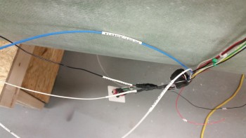
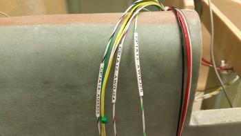
Here’s another couple of pics of my wire labeling endeavors this evening. The labels in the top pic are in their final location, whereas in the bottom pic those labels will be moved into their final position and given a final pass with the heat gun later.
•••
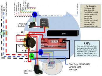
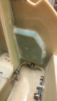
19 December 2015 — I spent a good 3-hour chunk of time at the end of this evening going over the nose electrical system. As I started looking at the battery compartment area to figure out my foam requirements: size, quantity, cutting angles, thickness, etc., I of course was mocking up the components that would reside in that space. As I was figuring out how & where things would go, taking into account wire runs & access, I kept coming back to the fact that I really had no one single account for the shear number of wires flowing in & out of my nose battery compartment. Intuitively, it only seemed like a half dozen or so, but it started turning out to be quite a lot more than that . . . quickly. It was clear to me that I couldn’t really plan out my foam requirements until I had a good account of where my components would go, and I couldn’t account for those devices without a finite accounting of the wire & cable flow.
After physically mocking up the main battery, nose gear back-up battery (which I’m now fairly certain will go forward of the main battery vs aft), battery contactor, battery buss, battery buss relay, and Integrated Backup Battery System (IBBS), I understood that I had to account for literally every wire and cable traversing Napster’s domain to finalize the foam plan for the battery compartment.
Once again, I know my CAD brothers will cringe (and possibly puke a little!) at my Neanderthal PowerPoint notes depicting the battery compartment area. I worked on this and researched my components for a few hours, and it finally got so late I just listed out the remaining items that I need to research/diagram and called it a night.
I did come out of this process with some good finds, which are listed in my RFI (“request for info”) block. The biggie is the realization that with so many wires coming into the battery buss, I’m strongly considering mounting it on the aft side of Napster vs the front side of Napster/inside the battery compartment.
•••
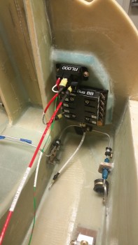
23 December 2015 — I started today by pulling the peel ply from the Battery Buss & the E-Buss control relay mounting pad 1-ply BID layup that I did last night. The layup turned out fine without any issues, so I cleaned it up and then drilled out the saran wrap plastic in the 6 embedded nutplates. I’ll tell you, this small stuff is the stuff that turns into time busters, since there’s so many little steps. And at the risk of sounding obnoxiously repetitive, that’s why I want to knock it out during the build –as well as for component planning purposes– so that I don’t end up with a completed airframe with no idea what I’m putting where!
Clearly I’ve been giving my electrical system a fair amount of attention. The main effort here with this mounting pad was to get the battery buss on the aft side of Napster (the F1-3 bulkhead) to minimize the number of wires going through Napster. In addition, it utilizes space that up until this point was unclaimed, but some good real estate. Finally, with the battery buss installed, I get a much clearer picture of where my holes need to go for the multitude of wire heading to the north end of the nose.
To get a minor jump on my electrical system, I went ahead and wired up the foundational wire runs between A) the battery contactor & the battery buss, B) the E-bus controlling relay to the battery buss/switch/E-Bus.
The work on the Battery Bus area included labeling the buss and the wires, crimping on the correct terminals, and confirming wire sizes and wire lengths. Speaking of wire size, I committed a sin against Bob Nuckolls’ teachings since after reviewing my electrical wiring requirements I finally realized that I have a lot of long 14 AWG wire runs. The feed from the Battery Buss to E-Bus is ID’d as a 14 ga wire, but since I had an extra 10 ft or so of 12 ga red wire, I used that instead. That frees up my 14 ga wires for the really long runs where it would be a heck of a lot heavier to sub a higher gauge wire for the length of the fuselage, compared to the 2-3′ that I just did.
Below is the Battery Buss ATC fuse holder (bottom) and the B&C S704-1 relay mounted above the buss. The large red wire heading back toward F22 is the power wire from the relay to the E-Bus, which is normally unused unless the scenario I described last night plays out where the main alternator is cooked, fried or somehow otherwise inop.
The white wire on the bottom center post of the battery buss is the 10 ga power feed wire connecting to the battery contactor just on the other (fwd) side of Napster. This white 10 ga power wire will traverse Napster through one of the 2-3 holes that will all get drilled either below or to the right side of this new mounting pad.
Also, just an FYI for those folks not familiar with this system. The Battery Bus is so named because it is the only buss that is always hot with live power.
•••
2 January 2016 — Today I wanted to get to figuring out the taxi light, and to do that I needed to take out the gear strut so I could get a good look at the NG6B pivot assembly. Since I was working in the NG30 gear box anyway, I popped the aft cover off to reset the up-travel limit microswitch. Since I’m none too bright, a few weeks ago I meant to set it so that it wouldn’t raise up so high into the wheel well, went the wrong direction with the microswitch, and ended up making it go too high … where if I didn’t stop it, it wanted to make some minor crunching noises. Not good. Plus, I needed to add locknuts onto the new long screws I put in since when I bought those screws they only had the standard ones.
When I took out the gear strut and gently lowered the actuator gear tube down to the mount cross strut behind I couldn’t raise up the gear when I flipped the switch just a few minutes later. I checked the battery because my buddy Marco had an issue that he discussed with Jack where he didn’t have enough juice to power the thing. My battery was down to about 12.65 volts, so I put it on the charger and grabbed my bench top 12V battery and tried it. No joy.
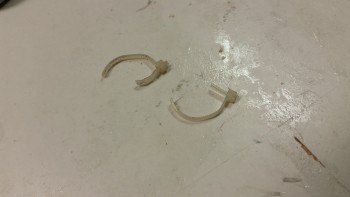
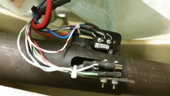
Ok, something was up. Well, it took me less than a minute to see that a couple of wires had pulled off of the gear up limit microswitch, as you can see in the pic below (behind the blue wire to the right). Obviously this happened when I lowered the actuator down to its lowest point, but why? As I started messing with the wires I saw that the zip tie holding the wires in place (the white one visible in the pic below) was really loose. I then checked the other side and it was just as loose. So in the immortal words of Steve Urkel, I said, “Did I do that?!” . . . well, the answer was yes. Apparently, I forgot to tighten them full tilt after I wired up the added gear up/down alarm wires.
But I learned something about this system, it’s critical that you have a 0.15 cent zip tie secured correctly or mayhem may ensue. I don’t think those small fast-ons have a ton of gripping strength, so putting a zip tie behind the connector flanges and into the heat shrink works as a failsafe to keep those wires where they’re supposed to be . . . on the tabs.
Anyway, problem solved.
Here are the culprits:
And here’s the new zip ties in place and secured correctly.
•••
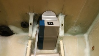
4 January 2016 — Today I mocked up the nose gear backup battery in its mounting position with the 1/16″ thick 6061 angled aluminum (delivered today from McMaster-Carr) mounting tab that I cut & shaped earlier. Here’s pretty much how it will look, only with about a 1″ high lip that I’ll glass in which will cross in front of the bottom section of the battery to keep in nice & secure in the pocket.
Here’s a wide angle shot of the battery compartment and nose gear back up battery.
•••
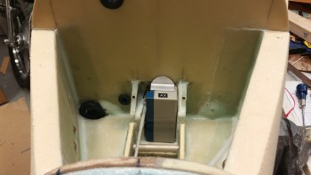
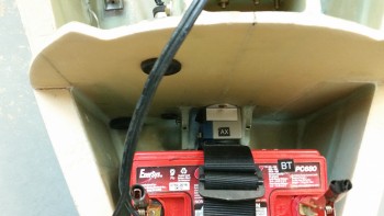
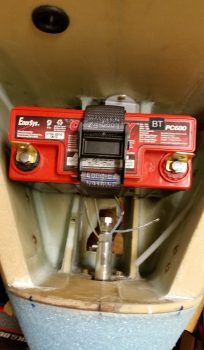
9 March 2016 — Today I got the battery installed into the nose battery compartment and the power cables clamped into place. Note in the pic below you can see the nose gear backup battery immediately aft of the main battery.
•••
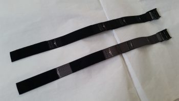
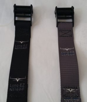
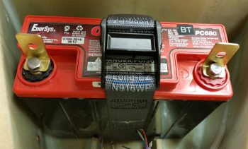
11 March 2016 — Today I received my custom battery straps to secure the main battery in the battery compartment. The strap and buckle are military grade that will easily hold a 15-pound battery in place.
Since the main cost was for prototyping up the first strap, I went ahead and ordered a second one in black.
I got these from Strapworks out of Oregon, and for the most part I’m pleased with them. I will say however that I think they could have done a little better job with the placement of the images, which for some reason seemed to be quite the challenge for them. Oh well, a minor issue in the grand scheme of things!
•••
15 March 2016 — Here are a couple shots of the battery strap in place.
It works as designed, keeping the battery in place nice and secure!
(Update: after playing around with this a bit I decided I’m going to glass in a small tray for just the bottom of the battery to keep it from sliding from side to side. The clamping pressure of the strap is great for keeping the battery from coming out, but since the battery case is so slick & smooth, it can slide a bit to each side)
•••
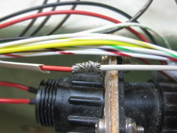
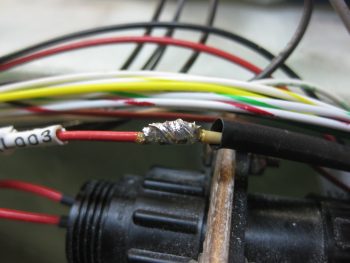
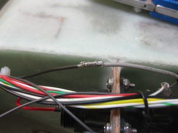
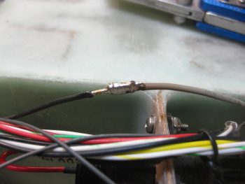
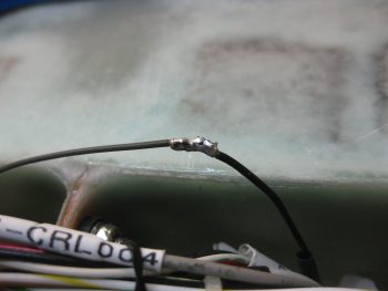
21 November 2016 — Today I started off with a little cleanup action on the nose gear wiring harness. I’ve had a bundle of excess wires sitting on top of the NG30 cover for eons now and decided it was time to clear them off. Also, instead of using butt connectors I opted for a more “elegant” solution and spliced the wires using a pigtail to secure the stripped ends of the individual wires together before soldering them.
Here is the first set of 3 that I did this morning. You can see the long 3-4 wire pigtail that I teased out of the stripped red wire on the left before cutting the rest of the stripped wires short in length to match the white wire on the right.
I then used the pigtail to secure the 2 wires together. I could have used a wire or two less on the pigtail and also cut it a bit shorter, which added to the slight excess in the wrap. No worries though, it still worked great.
I then soldered the wires together. I actually added just a tad bit more solder after I took the pic below.
Here’s wire set #2 getting spliced . . .
. . . then soldered.
And wire set #3 completed in the same fashion.
Here you can see all 3 wire sets spliced & soldered together. I used shrink tubing over the joint for added joint strength, then simply used the label as a second layer over the shrink tubing for even more added strength. After I finished with the shrink tubing & labels, I then hooked up up the battery leads and ran the nose gear up & down a bit to ensure the splices were carrying current, which they did.
•••
28 February 2017 — One good thing about not getting this plane built on schedule is that it allows for me to implement really good upgrade mods that would normally mean downtime & increased complexity on a flying bird. In other words, I can take just a scant bit of extra time and roll these new mods into the build plan in whatever area before I ever start in that specific endeavor. Two such mods that I’ll discuss below are the electric nose gear system and the heating system.
My build buddies apparently understand that I like bright shiny objects and will take off after them with aplomb if any catch my fancy. Well, Dave Berenholtz from OZ obviously understands this too well and sent an email asking me if I was aware of what Marc Zeitlin was cooking up in his evil lair. Apparently Marc was dissatisfied with the standard operations of the Automatic Extension (AEX) feature of Jack Wilhelmson’s EZNoseLift electric nose gear system. The AEX simply provides an automatic feature of retracting the nose gear after takeoff once the airspeed is above 90 knots, and conversely, will extend the nose gear if the airspeed is less than 90 knots. Short and sweet.
Well, Marc undertook about a year-long project to refine the AEX system, not just for Jack’s system, but any aircraft actuator-centric system (I’ll note for clarity that in Marc’s quest, apparently the “X” got lopped off the end of “AEX” and now it’s just the AE system). IMO, Marc’s system is fantastic in that by adding another airspeed switch, a throttle “microswitch,” and a laser altimeter, it provides a comprehensive set of parameters that must all be true for the Auto Extend to activate and deploy the nose landing gear:
1: Throttle less than 10% open
2. Speed greater than 40 knots (user programmable)
3. Speed less than 90 knots (user programmable)
4. Altitude at or below 350 ft. AGL
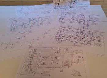
Ok! Wow, this is truly fantastic news for us Canardians! I printed out Marc’s description of the system and the electrical diagram and got to work since I wanted to assess how this would integrate into my system.
Initially, this all seemed too good to be true! Where was the catch? Well, as always seems to be the case there were two specific problems with this new system: the first in relation to my build and the other, a general operational requirement that I desired, which was offered in Jack’s original system but removed in Marc’s modification.
First, the operational requirement: Marc’s version offers no backup battery capability since Marc personally uses the ratchet drive backup system to extend the gear in case of an electrical failure. Jack sells his EZNoseLift systems with the option of the mechanical ratchet drive backup -OR- a small 1.2A backup battery that will lower the gear sans ship’s power if the electrical system fails. Hmmm…. Since I have the backup battery, this was not a good thing in regards to my system.
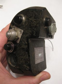
Next, as for the integration into my build? Marc’s version requires a 3PDT switch to control the gear up & down. My already terminated and installed throttle-mounted SPDT nose gear switch is in the “done” column and is perfect for driving Jack’s EZNoseLift system. Moreover, since this is an F-15 throttle handle, how this rare switch is mounted and its metal hat switch form factor make it very difficult to just pull, plug and replace with another switch. Moreover, I really have to say that I love my throttle handle just the way I’ve now configured it! On the pic of my throttle handle below you can see (mid-side handle) the stepped-hat nose gear up/down switch.
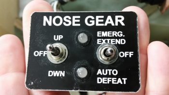
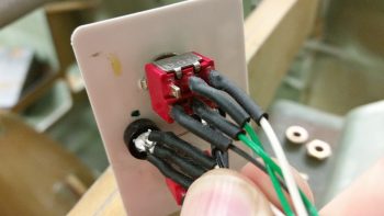
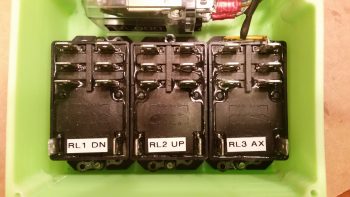
Also, one thing was clear as I stared down this road of integrating the new parts of Marc’s upgraded system while keeping the best part of Jack’s current system, and that was I really needed to truly understand and have comprehensive knowledge of how both these systems worked. To be honest, with so many versions of Jack’s system out there, I wasn’t even sure what my switch panel looked like! I went down to the shop and snapped a pic of the switch panel face . . .
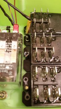
. . . and the actual wiring of the switches on the backside of the panel in order to identify the correct switches and wiring circuits.
After pondering my gear switch issue for about a day, out of the blue I had a Eureka moment: Duh! just swap out Marc’s required 3PDT switch with a 3PDT relay… right? Problem solved. Uh, but wait a minute sports fans. With this being a CANARD gear switch, a problem is presented in simply swapping a switch out with a relay since there’s that pesky “-OFF-” position on our gear switch that doesn’t translate over to a “middle position” between N.O. and N.C. on a relay. Obviously, on canards we don’t simply use a binary, all-the-way up or down gear position (except for TOs/landings), but use the gear switch to position the nose in a myriad of heights off the ground when parked. Thus, my requirement was to be able to hit the nose gear up/down position, have it run up/down for a few seconds and then move the switch to the “OFF” position to stop the gear from moving any forward. Again, with most aircraft you simply have an up or down gear position, but we Canardians apparently like to be eccentric!
I was at the juncture of simply knowing that I wanted to replace Marc’s required 3PDT switch with a relay that I could then subsequently control with my throttle mounted SPDT switch. But how? Not smart enough in the ways of electrons, I posted my dilemma onto the AeroElectric Connection forum. Within an hour Charlie England started off his response with a question that gave me my answer: “How about 2 separate 3 pole relays?” Yes, one relay would control up and the other down. When my throttle-mounted switch was in the middle OFF position, neither relay would be powered on to do any action so the system would be “at rest” . . . or OFF. I had found my middle position!
[Just as a point of note, since Marc’s 3PDT switch positions were wired to create 2-N.C. states and 1-N.O. state in the up position, and opposite in the down position, it allowed me in the end to only need one DPDT relay and one SPDT relay to replace the 3PDT switch.]
With the switch issue taken care of, now it was time to tackle probably the biggest electrical challenge I’ve ever faced. I had asked Marc & Jack, et al, on the Cozy forum if there was a way to wire back in the 1.2A backup battery into Marc’s design to provide a means of getting the gear down if a total electrical failure were to happen. I had some back and forth on a type-of-relay question I had, but nothing on the backup battery except an expressed desire by some to see that “put back into the system.” With no real response, and having one solved problem (the new AEX system) creating a new problem (no backup emergency gear extend feature), I figured it was time for the proverbial: “Well, if’n you want somethin’ done yer gonna hafta do it yurself!” (Said in Ken Curtis’ Festus voice from “Gunsmoke”).
I spent a day and a half deconstructing both Marc and Jack’s respective systems, and then ala “Tony Stark” (without the flare, billions of dollars, Hollywood CGI or Jarvis) I melded the backup battery feature from Jack’s system into Marc’s new design. Thus, after chasing imaginary electrons around on paper over a couple of days I was finally able to meld the backup battery and emergency gear extension feature back into this promising new & improved system!
After verifying that my new combined design worked, I then cleaned off all my specific extraneous system info to then submit a generic copy onto the Cozy forum. I received word back from Marc Zeitlin that it would work as per my (actually his & Jack’s) design, with a number of “why-didn’t-you-use-this-component-vs-that-one” type questions, which is great since that’s how system designs are optimized. So now I have some system design “homework” from Marc that I will attempt to iron out.
Regardless, doing nothing else from this point on (besides buy all the required components!) results in a new baseline electric nose gear system that provides a very usable AEX system and allows me to incorporate the backup battery feature/emergency gear extend feature.
If you’re curious, here’s a final thought on reasons I chose the battery backup system vs. the mechanical ratchet wrench backup gear deployment system: the battery weighs considerably less, takes up no panel space as does the mechanical unit, and most importantly –for me– if I’m working any non-standard issue while in the process of landing, I don’t want to be messing around with a ratchet (which itself weighs as much as the small backup battery) and spending time getting the gear down when the flick of a switch will do it for me. Finally, a very important thing to consider that I learned while flying in Marco’s Long-EZ is that IF YOU DROP SOMETHING on the floor, it is no longer something of use to you! And unless you tie off that ratchet handle, it may end up being nothing more than added weight in your airplane while you WISH you had a means to get your nose gear down [just saying . . . IMO!]
•••
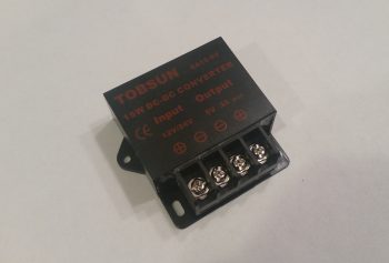
3 March 2017 — I’m starting to receive my component orders to implement that Marc Zeitlin’s new AEX system. I have yet to order the actual Laser Altimeter, but pretty much everything else is on its way. Below is the 12V-to-5V converter that I just got that is needed to drive the 5V laser altimeter. I wasn’t sure which one to get so I just bought the same exact one that Marc has since his system is working. Hey, if it works, don’t mess with success . . . right?!
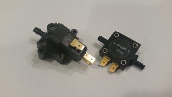
The other components I got in (as if I didn’t have enough of these things!) were 2 different airspeed switches. The one to the left is a Normally Closed airspeed switch and used to sense when the aircraft is less than 90 KIAS. The one to the right is a Normally Open airspeed switch that senses when the aircraft is traveling 40 knots or faster. These will be installed in series so both parameters must hold true for the AEX to function (along with the throttle being retarded to <10% power and the laser altimeter reading less than approximately 350 ft AGL).
Marco had a question on my last blog post regarding Marc Z’s system that I wanted to clear up here. Here’s Marco’s question:
This is an excellent point, and I should have clarified this in my last post. The answer is NO, the gear will not go back up because the AEX circuit latches. Only by cycling the gear switch all the way down and back up will it then raise the nose gear on the command of the pilot to very specifically override the AEX system. Otherwise, the AEX will keep the gear deployed until the pilot either lands the plane or cycles the gear switch toggle to intentional raise the gear. I’m glad Marco asked this question so I could clarify this point!
•••
10 March 2017 — Today I received an order from Mouser with everything but the Laser Altimeter that I’ll need to implement Marc Zeitlin’s new nose gear system AEX mod, combined with Jack Wilhelmson’s original emergency backup battery feature. After sorting through a myriad of revisions on the melded, morphed version that falls between Marc’s new system with Jack’s old system, I think the new AEX with battery backup and emergency extend is about the best version it can be.
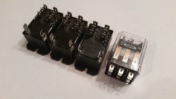
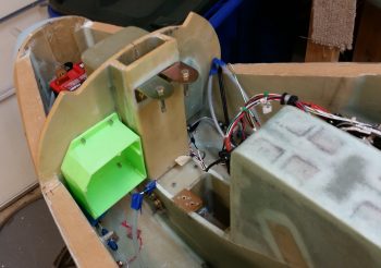
There are some tradeoffs of course with this new system, and some of that will be in weight. Although I guesstimate it’s not huge, I’m thinking this new system will be a bit heavier with the required laser altimeter and beefy relays in the mix. To offset some of the added weight effect, I’m mounting these new monster relays in an enclosed box on the left, aft side of the Napster bulkhead. That should help a tad with moving the CG ever so slightly forward.
•••
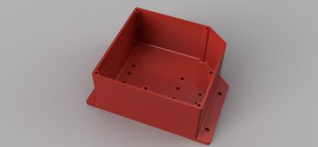
19 March 2017 — Over the past couple of days I’ve been designing what I have come to term the Relay Control Unit (RCU) box in CAD [prior to this multi-day endeavor I spent a day and a half rewriting & reconfiguring John York’s CSA article on installing FeatherLite’s strake & strake leading edge kit specific to my build, and adding in all my past strake construction notes from Mike Beasley, Bernie Siu, Wayne Hicks, Dave Berenholtz … just to name a few].
With the incorporation of Marc Zeitlin’s new wiring for the nose gear Auto Extension System (AEX), which is essentially a redesign of Jack Wilhelmson’s entire electrical scheme for the nose gear, I wanted to get this new system as organized and compartmentalized as possible. In short, I wanted the rats’ nest of wires gone and out of my nose compartment.
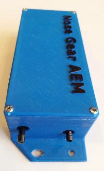
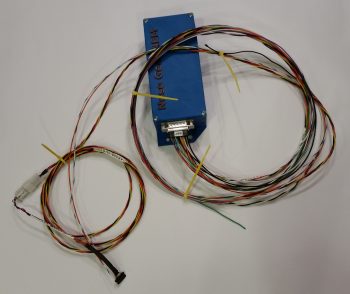
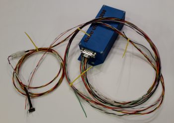
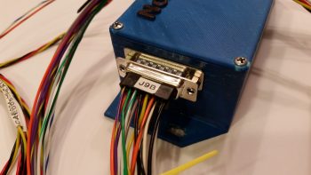
Now, the 3 main components making up my new electric nose gear system is still Jack’s electric nose gear actuator at it’s core, with the actuator motor and limit switches all tucked away under the NG30 cover. The wiring exits the NG30 cover via a 14-pin AMP CPC connector and heads in two directions: 1) the new Relay Control Unit (RCU) that will reside on the left, aft side of the Napster bulkhead, and 2) the new Auto Extension Module (AEM) which is simply a replacement unit for Jack’s AEX box. The AEM will sit in the same spot on the front CL of F22 in the top, aft notch in the NG30 cover. The RCU will tie into the system via a 19-pin AMP CPC connector while the AEM will be connected via a 15-pin DSub connector. Beside the larger backup battery and laser altimeter, there are minor few connections to the Triparagon, P4 Throttle Connector, and panel switches. But for the most part, the lion’s share of the actual nose gear electrical system is contained within 3 major components: NG30, RCU & AEM.
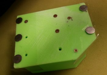
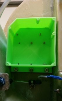
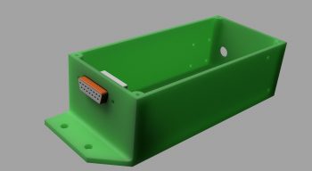
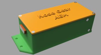
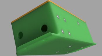
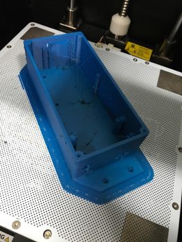
I was drawing up a version of the box I wanted in my antiquated TurboCad system, when in a discussion with Marco he graciously offered to 3D print the boxes for me (maybe not quite understanding that my CAD kung fu wasn’t up to par with his!). He had to redraw my neanderthal CAD drawings into Fusion360 but in the end came up with the awesome box rendering you see below (note: the angled corner is the top left box corner and is specifically shaped to allow it to fit with the curvature of the Long-EZ’s nose at its install point).
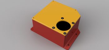
After some further discussion we came up with the lid design that will also be the attach point for the AMP CPC connector, since –YES– space is tight!
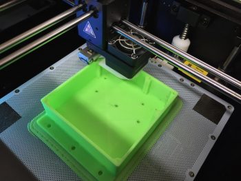
After confirming the myriad of little details on this box, Marco pulled the trigger and made our RCU box collaboration a reality. Pretty cool, eh?!
With the RCU box design complete and construction underway, I then got to work on designing the AEM box.
•••
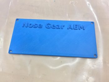
20 March 2017 — With the Nose Gear AEM box designed in CAD and sent to Marco for final collaboration and then 3D printing, I got organized to start wiring the internal components of both the RCU and the AEM. Since the weather is getting better only sporadically, with the seemingly incessant high winds as the norm, I figured I would trudge on to finish up as much of my electronics as possible until good weather allows me to fly & glass.
The first order of business was implementing the $1.49 clamp I picked up at Michael’s to allow me to employ the fixed iron method that is detailed in a Youtube video that Marco sent me, and also as I had seen prior in an EAA soldering video (featuring one my local Chapter 186 members, Dick Koehler). After using this method a bit without the clamp, I really liked it so I bought the clamp and made up my poor man’s version of it:
And here’s the YouTube video on the fixed iron method:
Ok, let’s talk about box configuration. For mainly external reasons, I needed my RCU box to be no more than 2.1″ tall internally. This meant the space for wiring connectors would be tight, and might have meant a fair amount of soldering, which as you can see above, I was fully prepared to do! ha!
Well, late last summer I had disassembled a friend’s dishwasher to get rid of it and recycle the parts. I threw the wiring harness in the garage to use for test wire (vs Tefzel) any time I needed “trash” wire. Well, I had it upstairs since I was cutting off pieces of this wiring harness to test circuits, and low and behold I found some 90° right angled 0.25″ FASTON connectors on the harness. I cut them off and inspected them closely and was able to pull away the wires’ outer insulation from the plastic retainer to reveal bright shiny copper underneath. Since the clamp part of the connector was spotless, I decided these would work great for the 22AWG ground side of the relay coils and pressed them into use. Since I didn’t have enough, I bought a few more for the relay coils’ positive terminal sides.
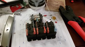
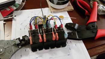
Here I’ve laid out the components further so the wiring flows in accordance with the wiring diagram. I crimped the normal FASTON terminals in place on the relay interconnect wires, first bending the terminals very slowly & carefully at a forward angle to give me just a bit more clearance under the lid. Also, you can see on the blue flag connector on the right relay that besides the 18AWG power wire, I crimped the flyback diode and 56.2 Ohm resistor into the terminal as well.
[NOTE: my relay interconnect wires came out too long –meaning too tall to fit under the RCU box lid– so I need to cut the wires shorter & re-terminate the terminals on the outside relays].
I then focused on relay #3, which is the heart of incorporating the small 1.2A backup battery into this system, as Jack has in his original nose gear system (Note: Marc Z’s version doesn’t have this relay since he uses the mechanical gear down backup system). I soldered the flyback diode in place between the relay coil tabs, then soldered the 22AWG black ground wire in place, with all this soldering taking place at the red terminal. I then soldered a Schottky diode (middle left) to the resistor going to the positive side (blue terminal) of the relay coil. This Schottky diode & resistor make up the backbone of the charging circuit for the 1.2A backup battery.
I then covered my solder joints with heat shrink tubing.
•••
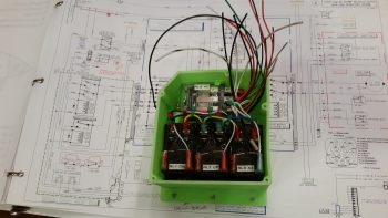
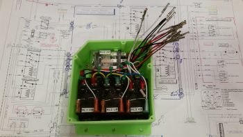
21 March 2017 — Today I finished wiring all that I could on the Nose Gear Relay Control Unit (RCU). My first task of course was to trim the lengths of the cross connect wires to the outboard relays (#1 & #3). I then re-terminated the wires with new red FASTON terminals and double checked that all was good with those.
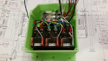
I then started cross-connecting wires from the 3 lower relays (black) to the top AEX relay (clear). One of the big challenges, which I think is a bit analogous to solving a puzzle, is to take the logical wiring diagram on paper and determine how the wires and components actually hook together in real life.
What looks like a long wire on the page can of course be no wire and simply a lead to a diode or resistor. Such is the case with the RXEF250 Minifuse that looks like a brown wafer overhanging along the top side of relay #3. Although on the diagram this shows up in the middle of wire run, in fact this Minifuse IS the wire run. The diodes at the bottom of the relay connections in the pic below is also pretty much the same way. On the diagram it looks like 3 diodes suspended mid-point in wire runs, when again they are the wire runs, all starting out at the AEX relay coil’s negative post. Out of 3 diodes hooked to the coil post, only one them is physical attached to a wire, while the flyback diode is terminated with the positive power wire, and one is simply a loner heading off by itself to a Common terminal.
The wires going every which a way again will get corralled, secured and terminated into the 19-pin AMP CPC connector.
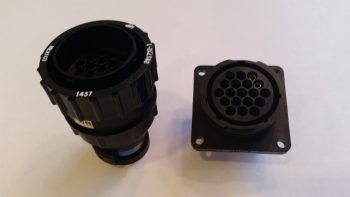
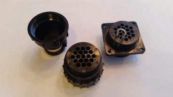
Speaking of connector, here is the AMP CPC connector for the gear RCU.
And a shot of the aft side of each connector half.
•••
22 March 2017 — Today I finished wiring all the components of the Nose Gear Auto Extension Module (AEM) as far as I could without having the physical box in hand. As I’ve mentioned before, the AEM is simply an upgraded replacement of Jack Wilhelmson’s Nose Gear AEX system that utilizes Marc Zeitlin’s design to incorporate a few more parameters into the Auto Extension system to pretty much eliminate annoying false-positive situations and ensure that really the only time the AEX will deploy the gear is on final approach when you actually forgot to put the gear down. To make the magic work, Marc added another airspeed switch (for a total of two), a throttle mounted “microswitch,” and a laser altimeter.
I decided to cram all this new stuff into a box approximately the same size as the original AEX box. Since Marco is 3D printing this one as well, it will have holes ready to go for mounting the internal components and some external mounting flanges for attaching the box to the forward side of F22 with Clickbonds.
The laser altimeter operates on 5 Volts, so it requires a 12V-5V converter. However unlike Marc Z. I chose to mount the converter up front versus the way he did right next to the laser altimeter (which is on the belly near the main gear). There is no right or wrong here regarding the location of the voltage converter, I just simply wanted to drive the weight forward and also hide the converter away in the AEX box.
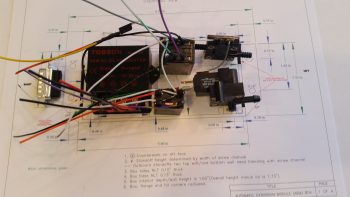
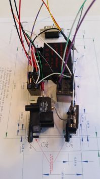
In between the voltage converter (right, below) and the airspeed switches (left, below) are two relays. These relays are unique to my specific system since these are the ones I needed to wire into the mix if I wanted to continue to use my throttle-mounted toggle switch to control the nose gear up/off/dn. These relays are fairly small and light, although robust, so the weight penalty is negligible.
Finally, in each pic I show the 15-pin DSub connector. In the very top pic, and the one below, you can make out the black bar that depicts the hole for this DSub connector on the actual-sized box CAD diagram lying below the components
•••
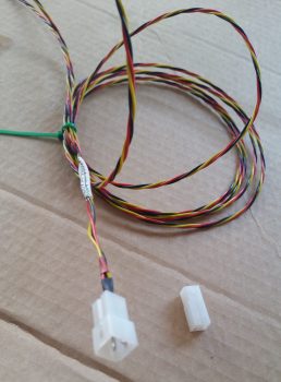
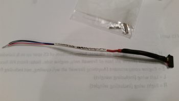
23 March 2017 — Today’s post is just a quick update showing the 3-wire braided cable build for the Nose Gear Auto Extend laser altimeter. These three 22AWG wires will provide power, ground and signal path from the laser altimeter into the Auto Extend Module (AEM).
After terminating the wire ends with mini-Molex pins (above) I then inserted the pins into a connector body.
•••
25 March 2017 — Today I received the Nose Gear RCU box in the mail from Marco. He did a great job and the relays fit perfectly! A little too perfectly actually . . . The holes are aligned exactly as I designed them in CAD, except I put them in a little too close to the end wall of each relay so that I won’t be able to fit a normal aviation/MIL-SPEC nut on the screw.
After thinking about this issue a bit I realized that the answer was fairly simple: nutplates. Nutplates are narrow enough that they’ll fit and even though a bit higher cost solution than normal AN nuts, they’ll definitely do the trick.
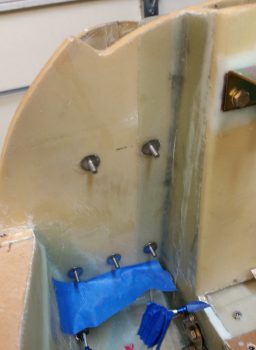
With the relay mounting issue out of the way, I prepped the box to be mounted with 5 Clickbonds. The mounting holes’ diameter were just slightly narrower than designed, so I spent a few minutes drilling those out to size. I then taped the back side of the box with clear packing tape. After roughing up the back sides of the Clickbonds with sandpaper, I cleaned them with Acetone. I then mounted them in the box, whipped up some 5-min glue and put a good dab on each Clickbond face.
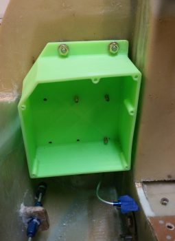
I then mounted the box on the aft side of the Napster bulkhead aligned with some position marks that I had previously made. I held the box in position for a little over 5 minutes to let the 5-minute glue cure.
With the 5 Clickbonds attached to the aft face of Napster I pulled the RCU box off of the bulkhead. The Clickbonds set well and the attachments were solid. I cleaned up some of the 5-min glue gunk and left the Clickbonds alone to fully cure.
While the Clickbonds cured, I measured out the dimensions I would need for the BID tapes for the top and bottom row of Clickbonds. I wanted at least a good inch from each Clickbond stud to hold it securely in place. I cut 3 plies of BID 2″ high and with a slight angle for the outboard side of the upper row, for a total of two sets of 3-ply BID. I then configured the BID plies in plastic for pre-preg setups and called it a night.
•••
26 March 2017 — I didn’t get the intermediate steps documented, but here is the final result of the Clickbond mounting for the Nose Gear RCU box. Again, I used 3 plies of BID along the top row (2 Clickbonds) . . .
. . . and 3 plies of BID along the bottom row (3 Clickbonds). After curing, I pulled the peel ply and cleaned up the goobers.
The RCU box is officially mounted.
•••
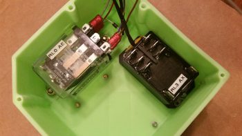
27 March 2017 — Today I started in on mounting the 4 beefy relays into the gear Relay Control Unit (RCU) box . . . fitting name, eh?! The first relay to go in was the clear cased 3 pole Auto Extension (AE) relay, RL000. It handles the actual engagement of the gear Auto Extension feature and also is a pass-thru for all the major electrons running the gear up or down.
I ordered this relay specifically with bottom mounting tabs, with the corner of the left tab needed trimmed diagonally just a hair for it to fit properly. It mounts with a 4-40 screw on each side, each coming in externally from the back. All the mounting screws coming in from the back side are countersunk to allow the back surface of the box to remain flat, which facilitates ease of mounting the box to the aft side of the Napster bulkhead.
Next relay up to get mounted inside the box was RL003, or the AX relay. This relay is the one I added back into the mix that charges the small 1.2A backup battery that was provided in Jack Wilhelmson’s original design. Relay #3 takes control of the system in case of a power emergency to drop the gear down using the 1.2A backup battery for power. In Marc Zeitlin’s new gear wiring design he doesn’t use this relay since his system incorporates a manual (ratchet) drive for emergency gear extension.
Finally, as for relay #3, I mounted this guy first since it has a unique feature that needed to be dealt with that the other two black relays don’t: down along the top side of the relay is the RXEF-250 wafer style fuse soldered into place that’s used during backup battery charging. Getting under this fuse to install the K1000-6 nutplate would have been a lot more difficult if I couldn’t get in from the side (where the other two relays sit) to mount the nutplate. After I mounted this relay, I put some double sided foam sticky tape underneath the wafer style fuse to keep it mounted to the front of the relay for anti-vibration. I also tipped the box right side up and glopped some E6000 adhesive (yep, the stinky stuff) onto each edge of the fuse to keep it secure to the relay, banned the box outside on the deck for a few hours while it cured and I took off to run some errands.
Upon returning from my errands (which included buying parts for the flexible sander Nick Ugolini describes how to build on his blog) I installed the last two relays: RL001 & RL002 [Note: Simply for space I truncated the relay IDs and labeled them on the actual relays with RL0, RL1 … etc.). As you can see, these two relays simply control gear up and gear down, respectively. All went well except for the life of me I couldn’t find a 6th K1000-6 nutplate to use on the top side flange of RL002. After searching for a good while, and simply not finding the pack of 23 I show having on hand (simply maddening!), in order to get this thing wired up tonight I improvised, adapted and overcame by using an aluminum binder stud, cutting off the top and then quickly Dremeling a not-so-pretty slot for a bladed screwdriver. I doused it with a good measure of blue Loctite and in it went… Voila!
Here’s another shot of my mounting improvisation . . .
Over the next couple of hours I confirmed & verified the wiring in this box matched exactly what was on the diagram. Having had to pull all the terminals off their posts, I used a pair of channel lock pliers to compress the terminals just a bit to ensure their clamping pressure was nice and tight. I then slowly replaced all the terminated wiring back onto the relay posts, performing a continuity check as each set of wires went back in. After all the wires were back in place, I zip-tied them into place to ensure no wires would be vibrating and wreaking some future electrical havoc by gnawing through a neighboring wire, etc.
Here’s just a closer shot of the internal RCU box wiring . . .
I then cut & terminated all the wires with AMP CPC sockets. Again, as I finished each wire I performed a continuity check to ensure all was electrical good on that wire circuit from source to connector.
With all the RCU box wiring set to be terminated into the AMP CPC connector, I called it a night.
•••
31 March 2017 — Here’s the Nose Gear Auto Extension Module (AEM) that will replace Jack Wilhelmson’s original AEX feature. I sent the pic below to Marco to help show him why I had a requirement that the AEM box be 1.8″ or less: since the AEM box will be mounted in the old AEX box spot, where I have a notch in the top aft side of my NG30 cover that is just a hair wider/deeper than 1.8″.
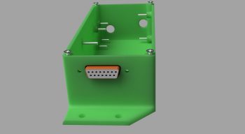
After a number of discussions back & forth with Marco on the particular specs of the AEM box he was able to generate these fantastic renderings of the box.
Here’s the initial rendering.
Then one with the lid and raised letter labeling.
One of the aft, left and top side.
Finally, one showing the internal standoffs for the two airspeed switches and mounting screws. As you can see, he has included the 15-pin D-Sub connector in the renderings as well.
•••
2 April 2017 — After some trials and tribulations with his 3D printer, Marco was finally able to get a good print on both the AEM box . . .
… and the AEM box lid.
I pulled the trigger on the Laserware SF11/C laser altimeter to have all the components required to implement Marc Zeitlin’s new nose gear Auto Extend System, with a twist of course: the backup battery emergency gear extension feature.
To get an idea of what it will look like installed, this is Marc Z’s laser altimeter installed on the inside of his Cozy gear leg cover. Of course the Long-EZ doesn’t have this gear leg cover, so my laser altimeter will get installed inside the hell hole near the gear. Also, note in the pic below that Marc mounted the 12V-5V converter near the laser altimeter, whereas my converter will be located in the AEM box above.
It’s been a bit of effort to get Marc Z’s new gear system implemented, especially with redesigning the 1.2A backup battery emergency extend circuit back into Marc’s scheme. But in the end I think all this extra effort will definitely result in a much more refined, simple, optimized and user-friendly nose gear system.
•••
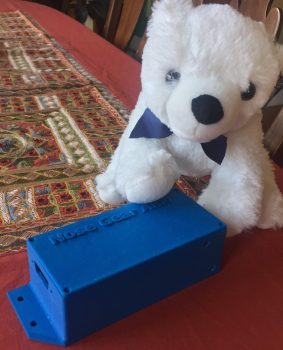
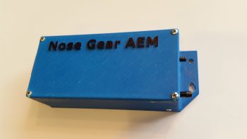
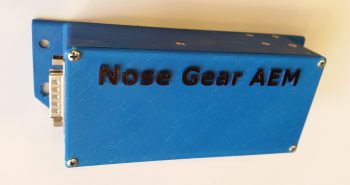
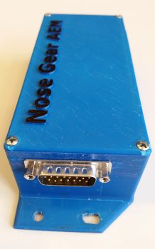
4 April 2017 — I got this pic from Marco showing my finished Nose Gear AEM box and a United Airlines bear he picked up for my little 7 year old buddy (a friend’s daughter) who loves flying.
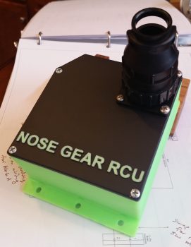
Also, the box Marco 3D printed for me for the Nose Gear RCU had a slight blemish on the lid, so I’ll hope he’ll forgive me for me filling it in a bit and painting the lid black. Here’s the finished Nose Gear RCU box ready for mounting into the aircraft. I will of course have to terminate the wires on the “B” side of the connector.
•••
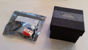
8 April 2017 — Today I got a nice little surprise in the mail. I opened up the box to find a very nicely packaged couple of items . . . hmmm?
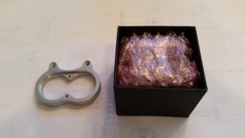
The plastic bag seemed to contain something akin to “aluminum knuckles” while the box had something wrapped in bubble wrap . . . what could it be?
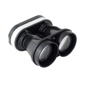
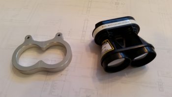
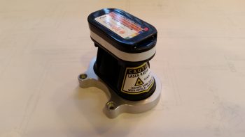
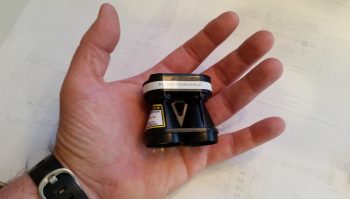
Ahhh, it’s the Laserware SF11/C Laser Altimeter & bracket that I ordered as the final crowning piece to implement Marc Zeitlin’s new nose gear wiring circuit! As with many actual Long-EZ parts I’ve received over the years, it’s much smaller & lighter than I expected, almost toy like (which of course it most certainly ain’t!). But then again, it does typically get mounted on a drone.
I did a quick test fit of the laser altimeter inside the unique bracket that is sold by Acroname, the place I purchased the laser altimeter.
Here’s a shot to help show the laser altimeter’s quite diminutive size.
I then proceeded to thread Clickbonds into the mounting holes on the AEM box and I took it down to the shop to test fit it. I’ve been thinking about a potential mounting issue in that by virtue of being mounted with Clickbonds to the face of F22, it will be difficult to get the box in & out and off those Clickbonds with the way it’s configured sitting down in that NG30 cover notch. You see, the original AEX box didn’t have mounting tabs so I actually glassed in a couple of hard points into the top face of the NG30 cover notch to mount the AEX box to the NG30 cover, vs. the F22 bulkhead.
My thinking is that I’ll elongate the bottom holes to allow for a front to aft twisting action as the box gets installed (technically not supposed to cut into 3D printed constructed stuff as I’ve learned since it’s not solid plastic, but rather matrixed plastic . . . but this was an oversight on my part in designing the box, although I did push both mounting holes up on the tabs significantly to allow for easier mounting in the NG30 cover notch… just didn’t do enough of what I had intended for getting this thing mounted). In addition, I’ll shorten the threaded Clickbond studs to the shortest they can possibly be while still gripping a mounting nut.
•••
10 April 2017 — Today I finished installing the Nose Gear AEM box to the forward face of F22. First, I cleaned up the 5-min glue that oozed out & dried around each Clickbond. I also sanded down the area around the Clickbonds for a layup of 2 plies of BID around each set.
Apparently Marco had told me that I needed to prep the lid-mounting holes in the AEM box –which of course I promptly forgot– so the there was a bit of separation between the box layers (slight splitting) at each corner from me installing screws into the screw posts. Thus, when I laid up my 2 plies of BID around each set of Clickbonds, I then mounted the box, applied wet epoxy to each corner, and then clamped the box on each side to compress the corners to remove the minor splitting.
Here’s another shot of the AEM box with the clamps applied.
When I laid up the 2 plies of BID over the Clickbonds, I of course peel plied the glass for a smooth transition. Also, I laid up the BID earlier in the day, so by late night the layups were cured and ready to be cleaned up. The pic below is from late evening.
•••
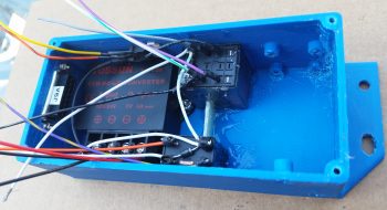
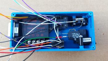
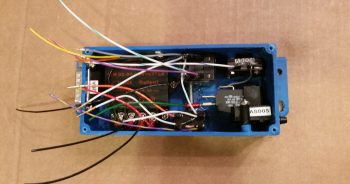
11 April 2017 — Today I finished mounting all the individual AEM box components and getting it wired up. I was ONE 4-40 screw short to mount the 12V-5V converter in place, so I had to get some hardware at my local hardware store (they have virtually everything!).
Before I left I gooped up both relays with E6000 glue and set them in their respective places inside the box. I then cut a piece of G10 Garolite as a spacer to just fit with very slight pressure against each relay and then slopped on some E6000 all around it as well. With the relays glued to the AEM box on two sides, and a spacer/support installed to keep the bigger relay (note that it’s mounted on the top inside of the box) from vibrating loose and causing issues, I think my non-screw-mounted components will be nice and secure.
BTW, if you’ve never used E6000 adhesive, you’ll understand why I wanted to apply it–out on my deck– and then leave for a few hours…. this stuff STINKS!!!! [You may also note by all the chicken scratches inside the upper right corner that I trimmed the standoffs on the top side down by about 0.050″ to get the top airspeed switch pitot tube barb centered in the sidewall hole].
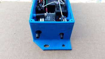
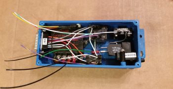
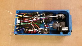
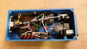
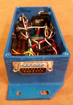
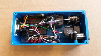
Upon returning from my hardware supply run, and still out on my deck for fresh air, I mounted the 2 airspeed switches into the AEM box. The top airspeed switch (AS004) mounts with 4x 3-48 CS screws while the bottom (AS005) mounts with a 2x 4-40 CS screws.
Below is a look at the airspeed switch pitot tube barbs sticking through their respective access holes on the left side of the AEM box. It doesn’t take a lot of pressure to align these barbs, so I tweaked the one on the left a bit after this pic was snapped.
Later in the evening, after a good amount of curing for the E6000 glue (read: way less stink!) I got around to cutting, stripping & terminating the wires with D-Sub pins. For some reason I had my wiring diagram D-Sub numbers inverted from top to bottom, so I spent a good 15 minutes straightening that out. I then started on the wires that terminated into the aft row of the 15-pin D-Sub connector (deeper into the box).
After I performed continuity checks on all my freshly terminated wires, I then mounted them into the appropriate positions on the D-Sub connector.
I then repeated the process by cutting and terminating those wires that are positioned on the forward side of the D-Sub connector (closest to the lid) with D-Sub pins.
I mounted the last/forward row of terminated wires into the D-Sub connector, and then zip tied the wires to secure them from any vibration damage, wearing or other issues.
Here’s a shot of the right side D-Sub connector end showing all the installed wires with terminated D-Sub pins.
Luckily it was a nice warm evening, because I then once again took the AEM box out onto the deck to goop up a few of the more sensitive connections with E6000, basically using it as potting material.
While the E6000 was curing I took the lid and colored the raised lettering with a very high tech coloring system…. sometimes known as a “Sharpie!” ha!
A few hours later I collected up the box and removed some the ‘spider webs’ that are typically when using this type of glue. I then mounted the lid with 4x #4 CS screws.
Here’s a clear shot of each end of the box: the J9 15-pin D-Sub connector on the right side, and the 2 pitot barbs poking out of their respective holes for the airspeed switches on the left side.
Barring any issues that may arise when I perform my ops function checks, this completes the construction of the Nose Gear AEM box.
•••
12 April 2017 — Today I started building the wiring harness for the AEM box. My first task was to configure the wiring connector that came with the laser altimeter. There are a lot of extra wires that come on this connector harness, so I cut those to a usable length in case I need them later, then wrapped them up and heat shrunk wrapped it to the cable harness. I then terminated the 3 wires I’m using with mini-Molex sockets and mounted them into the mini-Molex connector.
I then spent a couple of hours building the wiring harness for the AEM box.
I measured out the required wiring lengths for most of the wires, and estimated the lengths on a few of the wire runs to the panel. I performed a continuity check on each wire as I terminated the D-Sub socket on it.
Here’s a closeup shot of the AEM box D-Sub 15-pin connector with all the terminated wires installed.
•••
12 April 2017 — Today I laid up the final carbon fiber ply on the right side of the taxi light cover. It took some tricky machinations to get it lined up at the CF intersections, but it all seemed to work out. To be clear, I did use a “trash” piece of CF here for this final ply.
I checked it a bit later while the epoxy was still just a bit tacky, so I was able to mash down the edges/intersections CF.
After the carbon fiber layup cured, I did a knife trim and quick cleanup.
Here’s a shot of the left side. I need to still sand it down and hit it with one more application of epoxy. It’s still not going to win any beauty contests, but it looks a ton better than it did obviously when I first glassed it!
•••
13 April 2017 — Today I decided to pull all the existing nose gear wiring out of the nose to allow me to reconfigure the P1 and P2 connectors with the new Marc Zeitlin designed (along with my re-added backup battery) nose gear wiring scheme.
Specifically, I pulled all the existing nose gear wiring & connectors off of the NG30 cover to allow me to re-use the P1 & P2 connectors for the new nose gear wiring system. In addition, before I build & glass the top of the nose, I want to finish & paint both NG30 covers.
Here’s a shot of the bare NG30 cover from the right side.
My last official act of the evening (no pics… yet) was I spent a good hour sorting, selecting, and terminating wires to finish the initial P1 connector wiring for the new nose gear wiring.
•••
24 April 2017 — Today I set my sights back on my new nose gear wiring since the diagram was full of chicken scratches, notes, marker highlights, etc. One task that really needed to get completed was the deconfliction of P1 connector pinouts. You see, when I rewickered Jack’s original Molex connector and rewired the nose gear system through an AMP CPC connector for P1, I changed the pinout numbers. When Marc Zeitlin released his wiring diagram, he logically used Jack’s original pinout numbers. When I redrew the new wiring diagram, and merged Jack’s and Marc’s systems, I used the original connector pinout numbers instead of mine. This required me to go back tonight and re-label the P1 connector on the diagram with my pinout numbers vs Jacks, since I’m not going to pull the gear actuator side (B side) of the P1 connector apart to re-terminate it. It also required me to pull and re-pin the P1 connector (A side) terminals using the correct numbers.
However, I did build and add a jumper wire to pins 2 & 8 to allow me to use the P1 connector for routing of a ground wire coming out of the RCU. Doing this simply cleaned up the wire bundle and actually streamlined the wire routing.
I then soldered two 22AWG wires close to the terminal pin on each of the actuator motor power wires on the P1-A connector for the gear up & down transit LED indicators. After I soldered the wires in place I heat shrank the soldered joints to secure the wires & junction. I then finalized the A side of the P1 AMP CPC connector, covered the wires that traverse to the RCU’s P0 connector with a mesh cover, cut the remaining wires that will terminate into the P2 connector (upper left in pic below) to length and then snapped a shot of it all.
Along with the main nose gear wiring diagram, I also updated the P0, P1 and J9 connector pinout diagram pages.
•••
25 April 2017 — Today I focused on working to finish up the new nose gear system wiring.
I continued from where I left off last night and started by tying in the P2 connector to the mix. The P2 connector resides at the right midpoint mounting bracket on the NG30 cover, and was the original connect point of Jack W’s AEX unit. Now it has zero connections for the AEX function and is merely a break point for the wiring harness for making the removal of the NG30 cover EZ with just P2’s removal, and P0 on the RCU box. Besides an E-Bus fed power wire to the up/down limit switches, and an RCU box ground, the remainder of the P2 wires all deal with either LED indication of gear up/down transit, or AG6 warning annunciation for gear up and down.
I started by terminating the wires coming out of P1 into P2, installed the wires and closed up the A-side of the P2 connector with a cable clamp. I then selected and terminated all the wires to the B-side P2 connector, and installed the cable clamp (center top of pic).
Also, as you can see I (prematurely) mounted the AEM D-Sub 15-pin back shell (chrome silver-looking connector).
I moved the pic below up for comparison to the one above. As per Marc Z’s plan, I needed to solder a 560 Ohm resistor in series for the Laser Altimeter but forgot while I was building the aft side wiring harness for it. No big issue, sez me, I’ll just solder it in so it’s nice and tucked away inside the AEM 15-pin D-sub back shell (ID: Connector J9). Well, you got it… I forgot again! So I disassembled the back shell and spent a good half hour soldering one tiny 560 Ohm resistor in place. I insured I had heat shrink on the wire before I did my final solder, so was able to get a nice solid heat shrink piece in place over the soldered-in-place resistor & junctions. I stuffed all the wires back into the AEM D-Sub back shell, closed ‘er up and was back on track.
In addition to soldering the resistor into place on the AEM J9 side B connector, I also terminated every wire that came out of this connector. Six of 15 wires out of this D-Sub connector go to the RCU P0 connector, so I terminated those and plugged them into P0.
I also added another connector player into the mix at this point since this whole system is obviously controlled by the throttle mounted gear up/down switch. This meant running, terminating and mounting the gear up/down switch wires into the Throttle handle P4 connector (black & white twisted pair to upper left corner in pic below).
I also made the subsequent & requisite diagram updates,
•••
26 April 2017 — I did a bit more adminstrivia to verify the info I have on hand for my nose gear interfaces & integration with the electrical system. With minor mods an inherent part of the process, it pays to take a half hour or so to make sure all my diagrams have been updated.
I then proceeded to finalize the wiring on the nose gear RCU P0 connector. I then went the next step and prepped the main nose gear system power for connection to the E-Bus via a 10 Amp panel-mounted circuit breaker.
I then wired up the Emergency Gear Extend Switch that will be used in conjunction with the 1.2 Amp backup battery to get the gear down in case of an electrical system failure.
After finishing the actions above on the new nose gear system wiring, I took it down to the shop and installed the wiring harness, connectors, AEM box and RCU box into the plane. After double-checking (re-checking!) all the connections and pinouts, I fired up the new nose gear switch. The gear actuator sprang alive and carried the gear to its fullest down (nose up) travel. I then moved the gear switch to the up position (nose down) and I was met with only an audible click of the relay in the AEM box. Hmmm . . .
So, I rechecked all my connections again. Somehow I missed that I had inserted the big actuator power wires in the P0 connector in reverse… so I promptly fixed that issue. I reran the gear to see if that fixed the issue and it did not, although it did give me another data point since my new issue was simply now reversed: I could get the gear to go up, but not down. In addition, I was still met with just the audible click of a relay in the AEM box. I then removed the AEM box and the RCU box, took them upstairs and checked all the connections and circuit routes with a fine-tooth comb. Nothing.
Thus, I end this evening in perplexed fashion trying to brainstorm on exactly what the issue could be. Besides the reversed actuator wires that I quickly remedied, I can find nothing askew with the system…. so far.
•••
28 April 2017 — I’m happy to report I was able to troubleshoot the issue with the nose gear system wiring. It turned out to be an intermittent connection on a wire that goes to the down travel limit switch, causing the whole system to lock up in one direction.
Here’s a video showing the gear system tests. I did the first test solo, then a few hours later I did another one with Marco, who happened to be visiting.
I’m super pleased with how the new nose gear system turned out, and obviously relieved as well that it works!
•••
29 April 2017 — Today I annotated the wiring label IDs on the new nose gear diagram for the Nose Gear Up Transit and Nose Gear Down Transit LED indicators. I quickly printed out some labels for those wires, grabbed my stuff and took it all down to the shop to label and terminate these 4 wires.
After I cut these wires (that come out of the P2 connector) to a more workable length, I then labeled each one with the appropriate label [these were peel & stick labels since I’m currently out of the heat shrink labels]. I then terminated a socket onto the end of each wire and mounted them into their respective mini connectors.
I then tested out the gear up transit and gear down transit LED indicator lights as you can see in the very short video below (sorry, I didn’t get a shot of the LED indicator mini terminals).
•••
2 May 2017 — An issue that I discussed with Marco while he was here, is the fine splitting that is going on with the 3D-printed AEM box. Since Acetone melts –and thus “glues”– 3D printed material together, I clamped up the AEM box on the corners to close up the fine gaps & splits going on, particularly at the corners. I then wiped down the surface with Acetone. I waited about 6 hours and did it again, then left the clamps in place overnight to let it really set in.
I always believe things happen for a reason, and one really good thing to come out of my intermittent brown wire goose chase on the new nose gear wiring was that I found a loose terminal on the micro lever switch (sw088) that is 1 of 2 micro lever switches that drives the gear/canopy warning module. I reterminated that switch (the red FASTON visible in the middle of the pack) and re-secured the wires on that gear actuator motor flange with a zip tie.
•••
9 January 2018 — My first order of the day when I went upstairs to work on some even more tweaking of electrical diagrams was to hook up my nose gear auto extension system’s laser altimeter to my PC via the included USB cable to finally configure the settings.
After I downloaded and installed the Lightware terminal program, I then proceeded to set all the operating parameters for the laser altimeter. Of course that meant going paragraph by paragraph through the manual to make sure I didn’t screw anything up!
•••

