
Ok sports fans, the “big” reveal is here… my project for the last week in organizing, planning, and implementing is functionally complete.
Let’s get into it. First, the issue I had was simply not enough space to add more indicator lights to the top row above the HXr EFIS.
As I was finalizing my AG6 programming I pulled the “Fuel Pump” indicator off the row of lights and replaced it with the “Autopilot Servos Off/Pilot Controlled Steering On” indicator light (truncated of course). After my discussions with Rich regarding the AG6 annunciations, specifically on the Fuel Pump and Starter On annunciations, and how I wanted to manipulate those —but can’t given the inherent operational limitations of the AG6… just more detailed programming I wanted than available— I assessed what I deemed as my requirements for the indicator lights in conjunction with the AG6 alarms.
The AG6 Fuel Pump alarm I wanted was a flashing red light AFTER about 6 minutes had passed to notify me that I had forgotten to turn my fuel pump off. Since I’ll be routinely switching tanks now (vs my extensive high wing “Both Tanks” history) I figured that would be good to have. However, that would negate the simple “Fuel Pump On” notification via the AG6 since it won’t do both functions.
Before I get into more notifications and annunciations, lets get into my solution: converting a couple of my single indicator lights into 2-row indicator lights, with one component per each row, to give me more component indicator lights on the entire complement immediately above the HXr EFIS.
Here is the evolution of that in one pic:
From the top middle we have the initial blue 3D printed prototype that I drew up in CAD and tweaked a few times over to allow for 2 each 3mm (vs 5 or 8mm) LED lights per row. The top right is the standard PCB connector on the stock indicator lights. Below that, lower right corner is with PCB/LED lights removed. The bottom middle is after I got the hole sizes dialed in for a tight fit for the 3mm LED lights, where I then switched to black filament. The two left side light cases are where I worked on getting the height of the center horizontal divider where I needed to minimize light seepage from top or bottom being lit while the other side indicator is off.
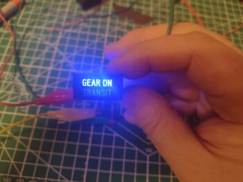
 My first test with an old indicator label installed on a new 3D printed case was without any resistor installed (pic 1). I then added a 470 Ohm resistor for the pair of blue LEDs, where you can see it not glowing quite as bright (pic 2).

The weekend was fairly slow build-wise given Valentine’s Day and some house work I had to get done. Over a couple of days I really focused on nailing down the circuitry of my top row indicator lights, and what/how I would meld the new 2-row indicator lights into that… here is the initial wiring plan for all that. A reminder that these lights are also all hooked into the push-to-test circuit and ran through their own dimmer switch.
 Here we have a new 3D printed indicator light case, or shell, on the left, compared to a stock one I received from the vendor on the right.
 And here we have a new 3D printed light case test installed into the top row light spaces on the panel along with an old stock light case. Can you tell the difference? (3D printed is on the right).
 With my wiring diagram in hand, test and checks completed, I then started installing the LED lights into the 3D printed cases. At this point I only have two of the 2-row indicator lights in the mix (with an option for a third if I need more component annunciations), with this being the second of the two that I installed the lights into.
For ease of assembly and soldering, I added the resistors onto the negative legs of the LEDs. Here are 820 Ohm resistors for each pair of lights, while on the first light assembly I made up I had separate 470 Ohm resistors for each LED light.
 I put an order in for new LED indicator lights, which on these pair of “double-stack” lights I really only need the front label pieces to pop into my light assemblies. Clearly why my test front label pieces don’t match the actual components these assemblies will annunciate.
And again, I’ll note that what I see in person is vastly different than the washed out colors my camera captures. The green on the top row here is much richer and deeper in person. This is for the FUEL PUMP (on) indication (pic 1), which just lets me know that the fuel pump is on. This then allows me to program the AG6 to alarm after 6 minutes if the fuel pump is left on (and I clearly am not noticing this indicator light… it happens).
The bottom white indicator (pic 2) is the closest pictorial representation of color and intensity of all these shots. This will be for the TAXI LT (on) indicator. Note the minimal bleed over from top light to bottom and vice versa… very acceptable.


The other double-stacked 2-row light assembly has blue on top for the STARLINK (on) indicator (pic 1) and the orange/amber (VERY washed out compared to viewing it in person) for the CABIN HT (“HEAT” on) indicator (pic 2). I’ll note that these represent the output of Relay 21 so these indicators will never be on at the same time, it’s either one or the other illuminated… with CABIN HT only on if I actually have the heat system powered on.


And a quick shot of my final wiring diagram/task list completed in getting all these indicators and alarms configured and finalized.
 Time to do a few final preps in the aircraft (now that the weather temps are just a bit less COLD!) before installing the Tri-Paragon and getting the instrument panel installed.
Pressing forward!