
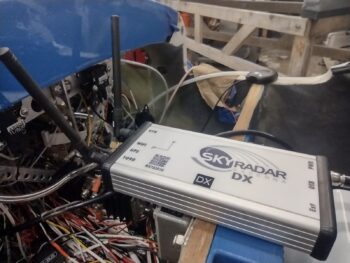
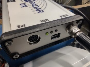
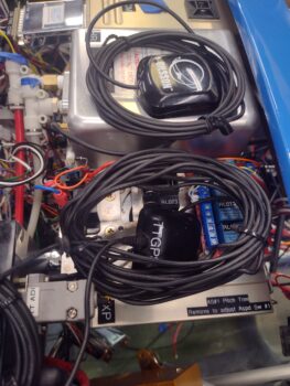
I started off today testing another component in my IBBS-powered suite of stuff: the Radenna SkyRadar ADS-B IN receiver, that I plan on mounting on the top centerline of the canard (pic 1). As you can see, the green power light shows that it is getting juice (pic 2). Initial power-up test good.
I also received more 1/4″ tubing push-to-connect fittings today which allowed me to finish configuring the Mini-X EFIS for its pitot & static connections. The incoming pitot & static feeds from the GRT AHRS will connect to the center/sides of the “T” connectors, while the open (forward) end of the pitot “T” connector connects to the TruTrak ADI. The ADI requires no static feed, so the end of the static “T” connector is plugged for future use.
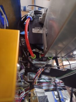
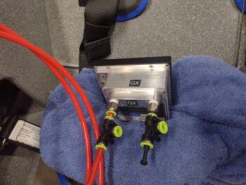 I then did the final official install of the Mini-X, 4 screws and all, and connected up the ADI’s pitot input (pic 1) as well as Mini-X’s pitot & static feeds to/from the AHRS (pic 2) [note the GPS pucks cable loops and initial positioning of those… assessing mounting]
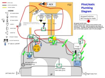
And here is my updated pitot/static diagram… besides the right side static port connection, the right side of the panel is complete. I’ll note that my configuration is a bit like a triangle, with the right side pretty much done, the left side (base) still needs plumbing, as does the forward (top) side with the 5 airspeed switches (AEX has 2) in and around the F22 and F28 bulkheads.
I’ll further note (if you read my annotations on the diagram) that I’m following Joe Gore’s lead (he’s helped me considerably on electrical stuff via the Aeroelectric Connection forum) in NOT plumbing the Airspeed Switches’ static ports since a good number of them have a tendency to leak (remember, Jack Wilhelmson didn’t utilize the static port on his original AEX unit). Thus, I’m “going ugly early” on this implementation.
 In the nose I terminated all but a few ground wires onto the G0 Ground Bus. The 3 ground wires that I didn’t finish yet is because I want to ensure/confirm their length and routing around the battery to allow me to secure them in a nice tidy bundle along with the other ground wires. That will come the next time I remove the battery. In addition, I purchased some hardware for the battery post connections that I’ll add into the mix the next battery removal/install.
 I threw a fuse into the Battery Bus fuse panel to allow me to test the circuitry on the Landing Brake. Now, although it lowered and retracted as per the labels on my throttle handle switch, the AG6 annunciation was backwards and the WOT=Landing Brake retraction feature didn’t work… after some thought I’m pretty sure I know exactly what’s going on with that and will fix it tomorrow.
 Not shown is the nose gear test. I have an issue there too with the gear retracting up fine, but the when I flip the switch for the gear to deploy (down) it’s currently dead… a no-go. I have zero thoughts on what is causing this issue, but the one positive and unexpected discovery that I made out of this is that tiny little nose gear back-up battery is not only strong enough to put the gear down, but that little sucker can lift the entire nose off the ground (and that’s without the counter-balancing engine installed). Impressive!
Yet another small but notable discovery I made was when I powered up the bird with the Master Switch. I initially thought I might have an issue with the pair of AG6 Warning Annunciators since they were colorless.
 It turns out (duh!) that when they are connected to the dimmer, and the dimmer is turned off, then it stands to reason they have no color (good to know… I’ll assess further).
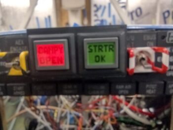
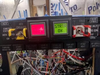
You may not be able to tell in the pics, but pic 1 is with the dimmer as low as it will go with the dimmer on. Pic 2 is with the dimmer turned all the way bright (again, the red looks washed out on camera, but the lettering is actually a very visible black).
Issue #3 deals with the top row indicator lights, where I ran through a few different blown fuses before I realized there is an issue with the Indicator Push-to-Test circuit where it’s shorting out somehow. Another troubleshooting task on my list to work tomorrow.
That being said, one of my parameter checks was to avoid using the PTT button to see if individual component indicators were working. Here I tested the parking brake handle indicator light, which clearly is working. That again points more to the PTT circuit as being the antagonist.
 It also probably goes without saying, but note that in every shot of the panel the left AG6 screen is constantly red with a “CANOPY OPEN” warning. This starts off flashing until I push to acknowledge that yes, the canopy is open. The red canopy warning will continue to flash (if I don’t acknowledge) and permanently stays red until the canopy is closed and the handle locking lever flipped back.
Finally, as you can see here I’m clearly working my way from the right side of the panel with the avionics mounted on that side. I’m working through powering up and testing every component I am able to (e.g. landing brake, nose gear, indicator lights) to work through every electrical and configuration issue while I still have free and open access to the wiring to troubleshoot what I need to.
Pressing forward!