
This blog post covers the past 2 days.
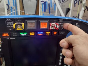
Of which, I spent multiple hours over the past couple of days slowly figuring out the issue with my Push-To-Test feature on my panel indicator lights. One issue was I had accidentally snipped a ground wire to the PARKING BRAKE ON indicator while wrangling all the wire together. The wire was (or appeared) intact as I just cut 3/4″ of the way through enough to cut all the wires inside, but not snip the wire in two. I cut and respliced that wire which solved the issue on my parking brake.
But why was I popping fuses? I checked EVERY indicator light wire for a short and found NONE. However, I noted as I pushed the PTT button in the millisecond before I saw the lights flash on and heard the pop of the fuse, I also heard a CLICKING sound. Like a relay.
I put in a 5 amp fuse at which point it was robust enough to not pop the fuse. But a row of LED lights should not require that strong of a fuse. I narrowed the clicking down to relay #11 in the nose, for the taxi light actuator. I ascertained the issue was the separate power circuit going into the lights for testing was going back through the power wire of the taxi light relay and triggering the relay. Not sure how, as I tried to ensure no wires were touching, but as one of the two taxi light indicator white LED lights is currently dead, and the taxi light is inop for the foreseeable future (a rebuilding of that light on the future to-do list), I simply threw a diode on the offending wire and called it a day.
I then installed a 3 amp fuse and called it a day [this issue came about AFTER my work on the taxi light circuit final wiring and pivot arm testing]. Problem solved.
 I then populated the GNS480 GPS mounting tube business end with its DSub connectors and 90° antenna connectors before mounting the tube into place.
I installed the front 8x #6 CS screws (4 each side) into the internal edge of the panel using Loctite as this is the final install.
I the wrangled and secured the wires on the GNS480 mounting tube before mounting the vertical securing arm into place.
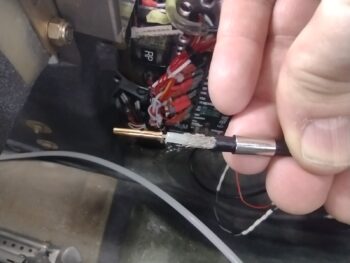
 With the GNS480 mounting tube wires and antenna cables in place, I was then able to determine the correct length required for the GPS antenna RG58 cable pigtail that connects the actual 90° antenna to the GPS antenna’s RG400 cable.
I cut the outer sheathing off as needed to then crimp on the center pin.
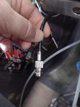
 I then snapped on the BNC barrel and crimped the sleeve into place to secure it. This is officially the last one of my antenna connector BNC connector installs on this bird! (barring any issues of course…)
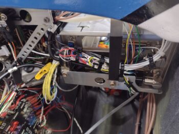
 I then spent well over another hour securing all the remaining stray wires on the left hand side of the Tri-paragon and avionics bay.
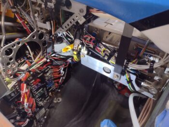 Here we have a long shot of the left side leg transit channel through the left side avionics area wiring that has been subdued… with prejudice!
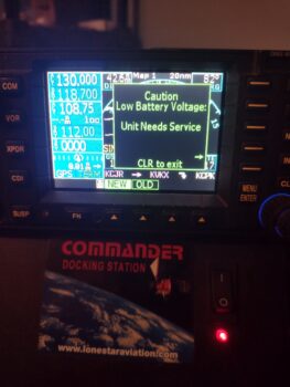
 Admittedly, I spent another good hour plus trying to get my GNS480 unit to seat inside the tube. I need to keep working to find the interference issue. But to eliminate unnecessary removal of the GNS480 GPS from its mounting tube —before I solve the clearance issue mystery— tomorrow I plan on installing a new internal battery inside the case to avoid it dying on me with the GPS installed in the bird… due to this caution message that’s popped up a couple of times.
 I know, classic problem avoidance… ha!
Moving forward.