
This post covers the last day and a half, as Jess and I returned back home from Charleston late afternoon yesterday.
After getting settled back in and unpacked, I went out to the shop to pull the peel ply from the rudder cable conduit sidewall internal conical layups before razor trimming the overhanging glass. After a bit more cleanup, I then snagged these shots of my completed task of rudder cable conduit sidewall exit moved aft by 5″ (yes, conduit will be trimmed much shorter to allow spring installation).


Having just installed the TCW Technologies Integrated Backup Battery System (IBBS) some questions arose on the circuitry. I had discussed it all in the past with Bob at TCW Tech, but in my attempt to contact him a few weeks back I couldn’t get ahold of him (I have since learned via the VAF forum that he sold the company). Regardless, I spent a good hour doing some initial research on that.
Back in the shop, with my mess making over with —at least for the time being— I pulled all the plastic sheeting out of the bird to get to work on the final hardware install for the pilot control stick (aft stick upcoming). To get the right armrest out, I pulled the seat cores and then spent about 10 minutes cleaning up some irregularly attached Velcro from when I unceremoniously plunked the seat cores into place. All is good now.
Part of the task to get the pilot control stick final hardware installed was to also install the elevator control tube. However, before that happened I needed to do the final routing of the control stick cable through the bottom access hole on the right side of the instrument panel bulkhead… BUT, since there is no space to get the bulky P5 connector plug through the populated bottom access hole in the bulkhead, the connector had to come off (note the color marks on the white wires).
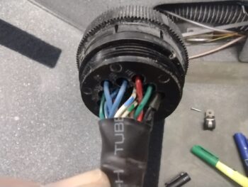
I got about halfway through removing the socket-terminated wires from the P5 connector when my already struggling (literally held together with tape) pin/socket removal tool gave up the ghost. I did a bit more cleanup and organized some stuff, but this task was kaput until I could get a functional removal tool.
Later in the evening after dinner, I spent 30 minutes online before finally finding a removal tool that could arrive in less than a week (off eBay of course). I also did another hour of research on my IBBS circuitry questions.
Today being the first Saturday of the month meant that we had our monthly EAA breakfast. I queried a couple of people at my end of the table to see if they might have the rare tool I needed, but none of them did. Ahhh, but my real mark was Joe at the other end of the table, who just recently completed a stunning RV-10. If anybody had an AMP CPC pin/socket removal tool, it would be him… and he did.
So I’ll state it again: Better to be Lucky than Good! ha
With my borrowed removal tool in hand (after another hour’s worth of research in the house) I got busy removing the remaining half of the sockets from the control stick cable’s P5 connector. I then routed the cable through the bottom right side opening in the instrument panel bulkhead. And after giving the plug components a good cleaning, started repopulating the terminated wires.
One short-term issue I ran into, which ironically was caused by the same underlying long-term issue, was that the final 4 wires I had to install were all white! Now, just as I noted in the pic of the P5 connector a little above, I had marked the white wires, and multiples of other colors, with permanent markers. But after all the handling in trying to use my broken removal tool last night, all but one color rubbed off!
Now, it just so happens that me in my brilliance decided 7 years ago to not “waste” my white wires with colored stripes on such mundane wiring as this, so I used colored Sharpies to create the stripes on the wires to color code them. Well, surprisingly (not!) the colors wore off… yes, from both 7 years ago and last night.
Thus I spent a good hour mapping out and toning out my wires to ensure that these white wires inside the P5 connector matched the white wires inside the externally pigtailed J5 jack for the Ray Allen roll trim servo. Yes, it took a bit but I got ‘er, so that is two connectors (P5 and J5) that were completed tonight.

After figuring out the J5 roll trim associated wire positions, I then finished reassembling the P5 control stick connector.
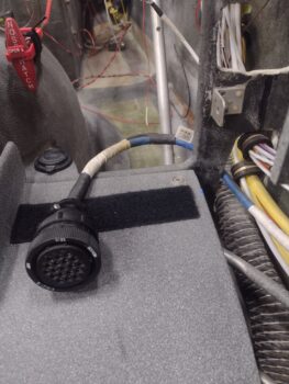
I then spent the next 45 minutes routing the control stick cable through the bottom access hole up to the P5 connector securing bracket. This took 3 iterations to complete since I needed to ensure enough slack to both secure the cable but also have freedom of movement with it attached to the control stick.
Speaking of the control stick, once I got my cable run completed I did the final install on the pilot control stick bracket hardware, to include mounting the elevator control tube, with 2 of the 3 bolts requiring castellated nuts and cotter pins.
I noticed when I grabbed the pic above, that I forgot to swap the bolt out at the base of the control stick and secure it with an aircraft grade nut, which I did next.

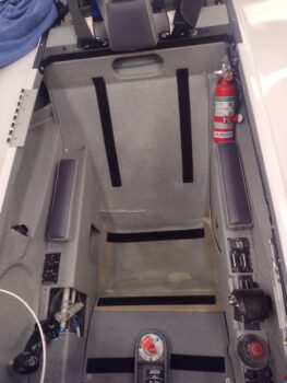
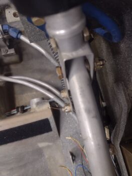
And here we have the elevator control tube installed. Yes, it looks a bit constrained here by all the wiring, which will be secured and routed just adjacent to the panel leg hole opening. Also note that in the “corner” of where the wire bundle crosses over the elevator control tube, if you look in the background you can see the Adel clamp that secures the control stick wiring cable (that’s the P5 connector upper right of pic).
Of course the rodends and jam nuts on each of the elevator control tube will be dialed in for final adjustment once the canard and elevators are installed.

Another quick back story is that when I made the corner bracket to install the pilot cigarette lighter charger I had not yet added and glassed the insulation on the nose wheel cover. Fast forward to this evening, and it was quite the challenge (with clearance being the usual enemy) to get the charger re-installed… but a good 30 minutes of finagling (and some choice verbiage) and I finally got it installed without having to cut anything.

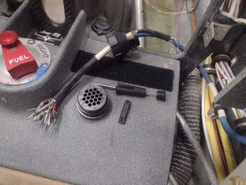
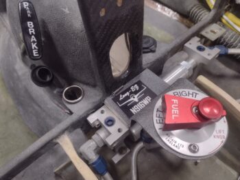
Here we have a shot from the aft side of the installed pilot seat cigarette charger, as well as the final control stick hardware installed (pic 1). And with the cigarette lighter charger cap open, ready for charging (pic 2).

And with my myriad of tasks completed, I called it a night. More to follow tomorrow.
Happy New Year!