
Today was supposed to be the first of a 3 day blitz where all focus would be on wiring up the bird, with small sideline tasks here or there. As you read below you’ll discover, as I did, that a major portion of my time today was spent with ‘Fein’ saw and Dremel tool in hand making a lot of dust as I cut out stuff to allow the ELT to both install in place and the clasps to work as designed. So my 5-10 minute “minor” task of installing the ELT mounting tray literally turned into a nearly 3 hour task… but it’s in!
Read on Dear Reader…
I started off today installing my padded carbon fiber wire-flattening plate and zip-tying that into place, before determining that I needed a -11 Adel clamp up higher. Again, this wire bundle is all the wires coming from the aft of the aircraft —that I had originally planned to run up the edge of the right outboard leghole edge— and it needs to be secured to the sidewall as flat as possible to keep out of the way of the elevator control tube.
After determining the best spot for the Adel clamp to secure the wire bundle, I then drilled a hole, prepped a RivNut and then floxed it into the sidewall.
 To keep the floxed in RivNut pressed against the sidewall nice and tight I used one of my clamps as a spreader for a few hours while the flox (MGS 335 with fast hardener) cured.
 My planned “sideline” (read: non-electrical related) task for the day was removing the GIB seat cores, straightening out the Velcro attach strips, which included trimming the Velcro and cutting it at the seams of the back seat hole covers and around the thigh support sump tank covers.
 With the GIB seat cores out of the bird, I then finalized the hardware install on the GIB control stick, with the top castellated nut requiring a cotter pin.
My next “quick kill” was to be a 10 minute install of the ELT mounting tray. I have to say this went south from the get-go, since after finally finding the right length #6 screws I promptly installed the tray with the securing straps in place… only to find that I missed the stamped “FRONT” and “BATTERY” markings on the straps. Of course, I had them reversed. Another 5 minutes to fix those. Not bad… done, right?!
 Yeah, until I actually mounted the ELT into the tray.
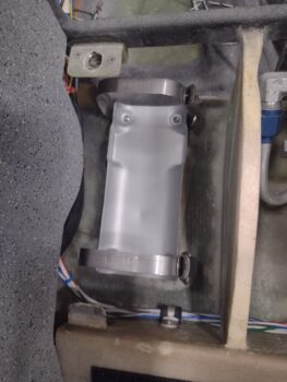
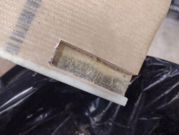
I quickly found that the aft/battery end of the ELT couldn’t seat due to the pilot thigh support tab being too wide front to aft. So I marked that for trim (pic 1) and trimmed ‘er up. After 2 rounds of trimming and vacuuming up the mess, the ELT actually fit and seated into place. Success! . . . right?!
Uh, no.
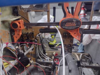
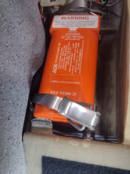
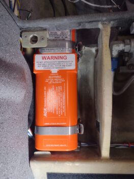
I then found that the vertical support rib for the pilot thigh support (to ELT’s right) was not allowing the ELT strap clasp handles to flip downward to allow engaging the tang on the clasp (pic 2).
Also, with the ELT seated fully down in its tray, it still wasn’t allowing the thigh support cover to seat into place. Clearly some relief was needed, so I quickly marked a strip on the aft corner underside of the thigh support plate for cutting…
 Which I did next. After checking its fit, I’ll glass it later.
 I then spent the next hour using my Fein saw and Dremel tool to cut a notch on the forward end of the thigh support rib and a channel on the aft side, all to simply allow flipping the ELT strap clasp handles up and down enough for the loop to engage the tang on the tray. This involved iterations of tray and ELT in, then out for cutting, as well as constantly reorienting the blade on the Fein saw to get the proper angle… and not inadvertently cut anything that didn’t require it!
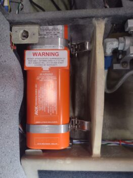
 My perseverance won out and I finally got the darn ELT installed (without connections of course)… Voila! While it put up a valiant fight, I won the battle!
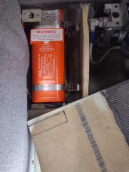
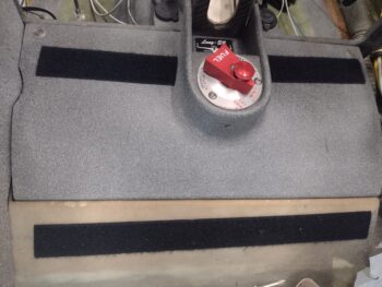
 The cherry on top was that the pilot thigh support cover fit back into place nicely after the aft corner notch was created… again, I’ll glass that later.
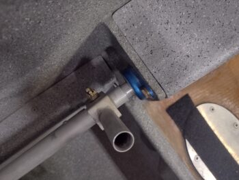
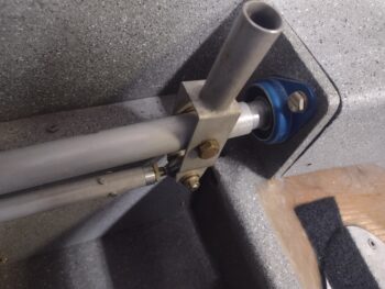
 After all that unexpected time spent on the ELT install, the right sidewall installed RivNut flox had cured, and I took the spreader clamp out and removed the washer. Here it is after a quick cleanup. I’ll let it cure overnight before installing the Adel clamp.
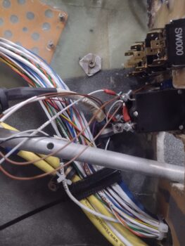
 I spent the next hour disassembling the P1 connector (lower right corner) and the P2 connector (upper left corner) to remove 2 unneeded wires in my quest to replace the “Gear UP transit” and “Gear DN transit” indicator lights with just one “Gear IN Transit” light.
I cut the 2 remaining wires that connect to the gear motor positive and negative leads to the indicator light and soldered in a diode on each wire. I then combined the diode leads along with one of the pair of wire leads going into the P2 connector, and soldered those up (black heat shrink in middle of pic). At the indicator light, the other lead will now go straight to ground. This allowed me to remove the pin and lead of the remaining wire of this pair since it is now no longer needed.
 Clearly, this means a total of 3 pins/wires were removed from the P2 connector. I do have some loose wires that I will terminate and install into those 3 positions to help clean up the wiring in the nose/NG30 area. Since my stock of AMP CPC pins were in the house, I’ll do that task tomorrow.
My last task of the evening was installing the 10 amp circuit breaker (CB001) for the nose gear power. The hardest part of that was weaving the CB with its attached wires in tow through all the myriad of loose wires inside the front of the bird. But it’s in.


Tomorrow I plan on getting the “ALT FIELD” CB installed, which will leave one left (which is currently attached to the TriParagon, still installed in the mockup panel).
Again, I still plan on focusing primarily on wiring and avionics for the next few days before I break back out onto other tasks.