
Today was all about finalizing the testing and configuration of both AG6 warning annunciation units.
After my discussion with Rich, the creator of the AG6 unit, I committed to pair down each AG6 to 5 vs 6 inputs to allow me to use input #6 as an audio out connection (technically through pin 7, which negates using Input 6) to the 10-channel AMX-2A audio mixer amplifier. Rich noted that hearing an audio warning while an alarm flashes increases your chances of noticing it exponentially. This exact dynamic has been stated by my buddy Marco (he’s even pointed out this phenomenon in some of his avionics videos during flights in his Long-EZ) and I totally concur… thus my emphasis on adding audio.
Before I get into the particulars of today’s task, here is the final (at least at this point in time) depiction of the AG6-A (aka #1) and AG6-B (aka #2) units. Since I only had 1 of the 5 “Ok” screens for AG6-B, I simply left them off. But as you’ll see below, they do exist.
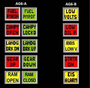 The above depiction shows 5 alarm inputs on each AG6, versus a week ago when there was 6 per AG6. Again, I combined (AG6-A) the 2 separate Gear UP/DOWN inputs into one to free up Input 6. On AG6-B I deleted the “Slow Speed” Input 4 and swapped it out with the Starter ON alarm from Input 6.
That all being said, I started off on AG6-A by swapping out the previous Carbon Monoxide alarm (that also feeds into the EFIS for an onscreen warning) for the Fuel Pump ON/OFF on Input 1.


I then spent nearly 2 hours working the parameters to get all the AG6-A alarms working. Again, I also combined the Gear UP alarm on Input 4 with the Gear DN/Locked alarm on Input 5. If you saw my blog post from yesterday, this eliminated the non-colored “ghost screens” that I was getting.
Finally, I configured AG6-A to output warning audio on Output 7.
I then focused on AG6-B, and started testing all the alarm screens.
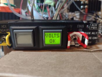
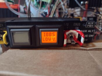
Input 1 on AG6-B is the Low Volts Alarm from the B&C voltage regulator. I’ll note that the alarm condition for all the amber or red alarm screens flash until I press the acknowledge button (screen).

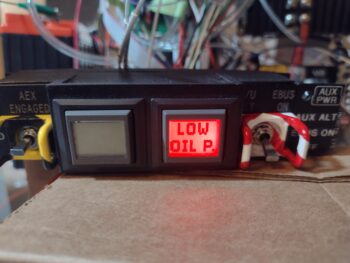
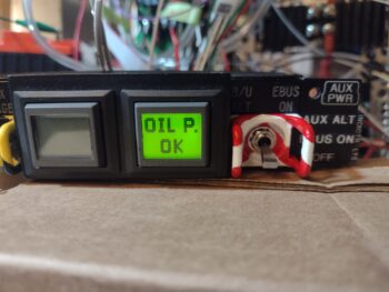
AG6-B Input 2 is the backup external oil pressure alarm (separate from the GRT EIS) that gets its signal from the Hobbs meter/backup oil pressure switch.
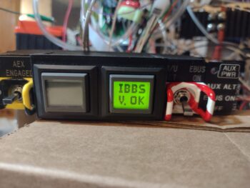
Input 3 on AG6-B is the low voltage warning light output from the IBBS.
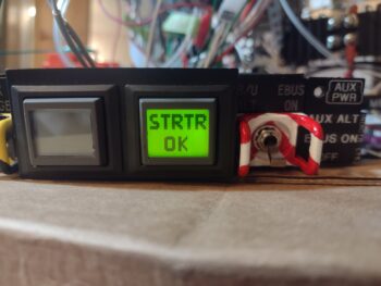
Ok, so Input 4 was the Low Speed alarm that I swapped out for what was on Input 6, the Starter ON alarm. The reason I pulled the plug on the Low Speed input was that originally I had it hooked up to an airspeed switch that was set at 70 knots. But as requirements for various components hooked up to it changed, I changed the airspeed switch setting to 90 knots, so off it came from the AG6-B . . .
and in its place is the Starter ON alarm. This is to monitor the starter in case it hangs up and doesn’t disengage. As I’m sure you all know, this is a very dangerous situation in that it will fry the battery if that circuit stays open too long. It’s the very event that burnt down Brian DeFord’s fairly new Cozy in a matter of minutes on the ramp.

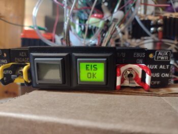
On Input 5 I have the GRT Engine Information System (EIS) external alarm. This obviously is a warning to scrutinize all the engine gauges to ensure all parameters are in spec and operating correctly.

And as with the AG6-A unit, I then programmed Output 7 on AG6-B to send the alarm-out audio to the audio mixer amplifier.
Tomorrow, with a little less snow, I plan on taking an even bigger bite out of my electrical to-do tasks to get the electrical system complete and the panel installed in this bird.