I have been working on my Electrical System since September of 2012. More recently, over the last 6 months, I’ve been trying to get it as close to finalized as possible before I head back to the States… and commence to start building in earnest. One goal that I had while being separated from snorting epoxy fumes and getting touchy-feely with itchy fiberglass for the past year of this build was to complete my electrical system wiring book. I want a solid plan to follow once I get to the point of wiring up this bird, and I don’t want to be in a position of trying to design my wiring system as I install it, or worse, take precious time away from actually wiring the plane to research out what I’m supposed to do, or how to do it. Of course, my overall goal is to have a very optimized, efficient and as Bob Nuckolls would put it, “elegant” electrical system (all that equaling ‘safe’ too!).
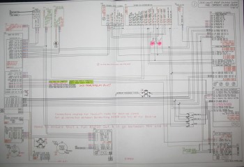
Pic below shows Switch page (L side) and Z13-8 Main Electrical System diagram (Lower L) along with five other electrical subsystem diagrams.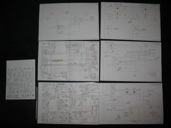
Of course another reason for me to document my electrical system & wiring, and the foundational research that goes into all that, is to have reference documents to go back to in case something just ain’t working right!
So a couple of months ago I felt my electrical system was to the point where I should start diagraming out the electrical subsystems. Thus, over the past couple of months I’ve started in on the individual pages–one for each subsystem–of the Wiring Book. Below is the ever-expanding and ever-morphing list of subsystem diagram pages for the Wiring Book (Green denotes completed or mature, yellow is currently being worked):
Z. Z-13/8 Electrical System
– Switch Configuration
1. Panel Components
2. Radio & audio system
3. Main Bus
4. Batt Bus
5. E-Bus
6. Nose Gear
7. Pitch & Roll Trim Systems
8. Lights: LDG, TAXI, NAV, STROBE
9. Engine Info Management
10. Fuel System
11. Cockpit Lighting
12. Landing Brake
13. Throttle Switches
14. Control Stick Wiring
15. Integrated Back-up Battery System
16. Alarm & Warning Systems
17. Charging & Starting Systems
18. Heater System
19. Electronic Ignition
20. P-Mag Ignition
The wiring pages for the individual busses (#s 3-5) will be created last after all the minutia is flushed out and sorted through for each subsystem. It’s amazing the amount of research, emails, and phone calls, etc. that goes into creating each subsystem diagram. Of course, it’s an understandable dynamic that more companies producing components for homebuilts gear them towards the RV crowd, simply because that’s arguably the most often built experimental in el mundo. Unfortunately, this can create issues for us Canardians as we fervently try to cram RV-oriented electrowhizzies into our prized EZs. Also, it’s simply a matter that a lot of these smaller companies just haven’t got around to engineering a solution between their and other products that can work in our canards.
A good example of this is when I had to contact both TCW and Trio to figure out how to get the Trio A/P AutoTrim function to work with TCW’s SafetyTrim Pitch Trim Controller. Both companies were of course fantastic, but it took a good day and a half to work out and confirm a solution. And that’s for just a few wire connections between two devices. Clearly most of us have a fair number of electrowhizzies in our birds, and luckily most of this stuff is figured out ahead of time . . . but definitely not all the time!
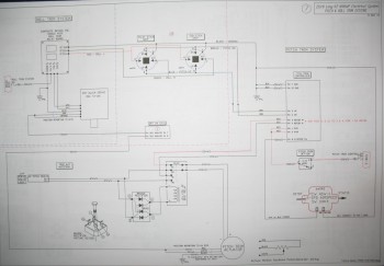
Below is a shot of my main wiring diagram for the Z-13/8 electrical system architecture that was developed by Bob Nuckolls from The AeroElectric Connection fame. I have of course taken the basic diagram and modified it countless times for my purposes. If you are building an airplane and don’t have this book, get it! I seriously don’t know how you could wire an experimental airplane without it.
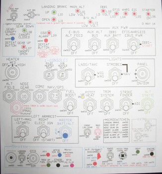
 Here below is a shot of my switches, circuit breakers, and LED lights diagram. Notice that each device is numbered with a specific code. These codes are depicted wherever the device shows up on any given wiring diagram. They’re also annotated on a spreadsheet that I keep all these device codes in, and will be incorporated into a wiring identification schema which will be labeled on each wire. Once the labels are on the wires, I’ll be able to look at any wire and its associated 12-digit code, tell exactly what device the wire is coming from and from what area (nose, engine compartment, etc) of the aircraft, what device and area it’s going to, and its function.
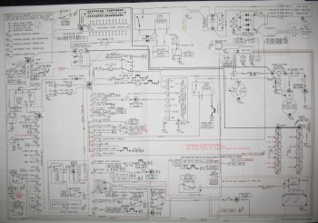
Below is a working copy of my panel wiring diagram. I spent nearly a week working off & on to upgrade the diagram so it depicted the Garmin GTN650 pinouts vs the Garmin GNS430W.
And finally, here’s a shot of the Pitch & Roll Trim Systems wiring diagram: