
Alright sports fans, a busy past few days… including a number of social engagements that knocked me a bit off my schedule. But I did get a good bit done.
I mentioned my chicken-scratched diagram to keep me organized on my wiring reconnects on the Dynon Intercom. However, toward the final wiring steps I found a wire that was not fitting into the matrix (green tape ID’d for pin 7). It was clearly part of the previous Intercom wiring (split for years between with wires coming from the front, from the GIB/aft and those on the panel mock-up), with ground pigtails coming off the shielding and a D-Sub socket crimped on the end of it. Clearly it was destined for the Intercom… I mean, what else in this specific area would it would be for?
 Well, first off, I had misread the small numbers on the face of Intercom wiring harness D-Sub connector and thought socket 7 position was open, but it wasn’t after a second look. I then accounted for every wire in the D-Sub connector, and determined I had NO open spots for a single wire. I guess I should point out that my mystery wire had no visible labels since it was encapsulated in the wire bundle.
I then connected Relay #9 to power to test it out and allow me to do a continuity check on the wires connected through it to both the COM1 (Garmin GNS-480) and COM2 (Trig TY-91) radios. I also toned out all the headphone, mic jacks and PTT wiring both front and back seats. These checks included all the shield grounds. All wires checked out and all socket connections were accounted for… the deduction in my investigation was clear: I had an extra wire in the mix!
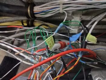
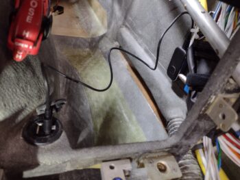
Begrudgingly, I removed zip-ties and pulled the big bundle of wires apart enough for me to find a buried wire in the mix that was labeled for “TCM001″ (pic 1). CM is the electrical component ID for the COM2 radio and 001 is the pin number. Just one big problem with this label: my COM2 radio has no required wire pinned on its connector at pin 1. I again deduced that this wire was yet another holdover from when I had wired up the panel for the Microair M760-REM remote radio, which I had planned on using for my COM2 radio but was forced to change my plans after they stopped selling them.
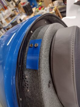
I decided that instead of pulling the wire out of the bundle to simply remove the labels and ID it as a spare wire (pic 2). Mystery solved and I pressed forward.
In related news . . .
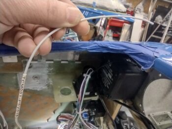
After some research I pulled the trigger on a BlueTooth module that connects via a 3.5mm jack to the 3.5mm socket assembly that I wired up to the Dynon Intercom. Here you can see both of those modules installed on the lower right sidewall, just forward of the right pilot armrest.
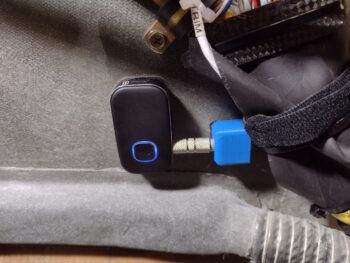 It took a little bit to figure out where I was going to mount these guys, as I originally had planned on all this being in the GIB area on the sidewall. I then figured if I was flying alone and wanted to use this Intercom function, I clearly couldn’t reach in the back seat to turn it on. Plus, the angle of the pilot’s seatback would make both installation and control manipulation a bigger pain than if I just ran it forward… EZ-PZ.
Finally, here is the recharge cord connected between the BlueTooth module and the USB charger (just forward of the pilot seat pad at the base of the center panel strut).
 In addition, over the past few days I’ve been dialing in the initial configuration test plate for the top GIB headrest mount for yet another video camera (speaking of video cameras, I have not yet addressed nor repaired the dead video camera wire in the left strake).
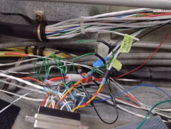
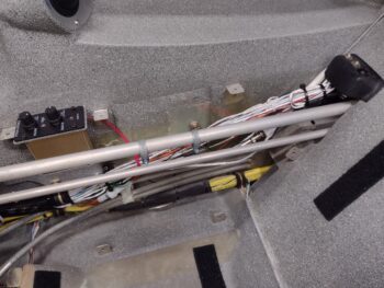
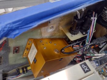
 So, after 2 days of constant machinations and concluding that whole extra wire investigation, and an hour-plus ordeal of getting that damn D-Sub connector secured to the Intercom bottom plate (I told you it was NOT going to be easy…what a PITA!), I’m officially complete with the Dynon Intercom wiring and installation (pic 1).
To be clear, I do need to install an inline fuse for the GIB Bose LEMO jack and then finish securing a few stray wires when I secure that fuse. Also, I need to finalize trimming and fitting the aft top edge of the right armrest to fit around the headphone jack bracket (pic 2).
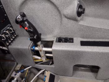
Here we have the right armrest set in place to give you an idea how the intercom will look after all bits and pieces are finally in place in this bird.
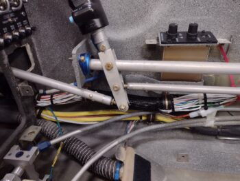
 After wrapping up the Intercom install on the morning of Day 3, I then got to work installing the Trio autopilot pitch servo on the right sidewall of the avionics bay. This install wasn’t too bad, but again it took well over an hour longer all told than what I had expected it to take.
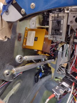 In the background, just over the pitch servo, is the P3 CPC connector for the pitch servo. This was the biggest pain and most time consuming to install due to the tight space required, and I still need to finish installing all the screws to secure it.
Again, a top down look at the just installed Trio autopilot pitch servo with the P3 plug connected (pic 1).
I then did the initial install of the GRT Mini-X EFIS into the panel… note that I still need to connect up its GPS antenna along with the pitot and static connections (pic 2).
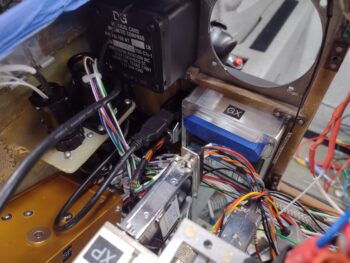
Thus, to allow me to pull it out of the panel for the pitot/static port connections I only secured it to the panel with one screw at this point.
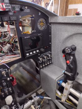 Yes, that Dynon Intercom wiring and install —as I suspected— was quite the ordeal. But given that I tested every connection, as well as the relay-driven COM1⇔COM2 swap via the top inboard switch on the control stick, I’m very happy with the install
—whew!
Pressing forward!