
Again, before I dove into troubleshooting the nose gear not-going-down issue, I wanted to knock out some low hanging fruit.
My first task was fusing the TCW Tech SmartStart unit before pressing a couple of buttons <secret?> to arm the starter for engine start. Obviously this arming step, and ensuring the indicator light lit up, were the only test on this system at this point.
 I also fused the StarLink/Cabin heat relay circuit (StarLink may get swapped for WXWorx Satellite WX depending on StarLink’s pricing and plans available) to test out the circuits. Upon flipping the StarLink switch on, the circuit looks good (a bit more on this below)….
 I then got to work on the nose gear down issue.
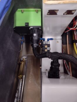
I checked the 2 suspect wires on the external P0 connector and they both were secure and looked good. But sure enough when I cracked open the Relay Control Unit (RCU) I saw the brown wire socket looking like it wasn’t in the socket hole deep enough… and I was right.
The wire just pulled out of the RCU-side P0 connector socket hole when I checked to see if it was secure. I’m guessing iterations of disconnecting the connector and reconnecting it challenged a weak-seated socket. I flared the little catch tabs on the side of the socket out a bit and then inserted it back into the socket hole… which was a bit challenging given the space to do it.
 And Voila! The nose gear functioned perfectly up and down with this socket back in the game.
I then put everything back together, put some flexible conduit over the wire cabling, and then did another test of the nose gear system to ensure it was working. All still good!
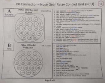
 I’m going to put a quick plug in here for both my wiring diagrams and the connector pin-out diagrams (below) that made this nose gear troubleshooting much easier. Although not perfect, I’m glad I took the time over these past years to keep them mostly updated!
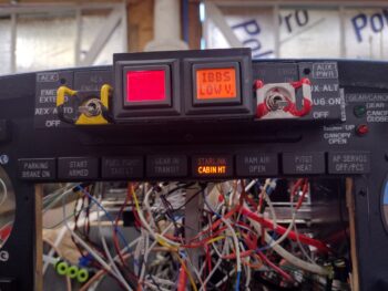
 Now, when I fused the StarLink/Cabin Heat power relay system, the CABIN HT light was not illuminating when I flipped off the StarLink switch. Although StarLink has priority and will cut off power to the cabin heating system, with the StarLink switch off the CABIN HT light should come on when the Oil Heat System is turned on. But it wasn’t (clearly this pic was after I fixed it…)
 I’m not overly surprised, as the access to the wiring for the heating system (both oil heat and seat warmers) is virtually non-existent. The wire I could get access to (barely) was one that I hoped would power this light, but upon closer inspection it wasn’t the right one. Moreover, if I tie into the power wire than the CABIN HT light will simply stay on all the time… a bit silly in my book.
So to get the Oil Heat side of the system to power the light, after multiple crazy attempts over 15 frustrating minutes, I punted and decided to join the ranks of hacks and cheaters. And although I’m not proud, I am happy this task is complete.
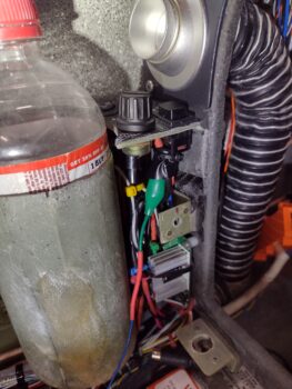
I’ll start by noting that this is not a safety-of-flight indicator, just a “nice to know” one. So I used the end of the same alligator clip I used to find the good terminal off the switch, cut it and spliced it to the blue 22 AWG light wire, wrapped the clip with electrical tape and then zip-tied it to secure it. Janky! But task complete.
I also did a function and fit test of the original design prototype for my Dual GPS puck mounting bracket that I designed up in CAD. After the initial check, I tweaked the dimensions a good bit before 3D printing this one out in ABS for actual install.

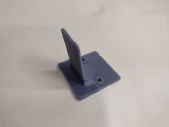
How does it work you ask? Well, I just discovered after all these years that the bottom plate of the Dual GPS puck has a slot to allow attaching it to a band. The thickness of the slot is 0.09″. The tab on this mount is the same thickness, so the puck firmly slides onto the tab to securely mount it into place.


And this is where I plan to put it, so I can simply pop the nose hatch to turn it on & off.
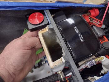 The one downside is that the screw holes that I need to drill to secure it to the aft side of the Napster bulkhead are lower than the IBBS unit on the front side… so that will have to come off for a bit after I remove the battery again to complete this install.
 My priority tomorrow will to get the panel indicator lights Push-to-Test function online and to stop popping fuses! Then I’ll get back to work getting these panel components and circuits tested out so I can finish up installing the remaining avionics in the panel!