
I had to stop by the airport to pay my hangar lease, so I figured I would hop by the hangar to “feel my space” and brainstorm about future tasks.
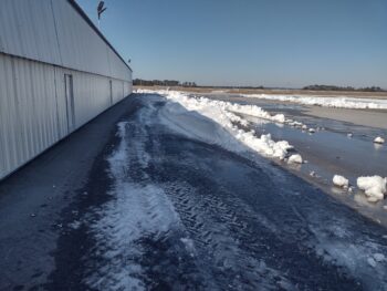
While nearly the entire rest of the area is back to business after this quite heavy snow storm, apparently the airport needs some remedial training in snow removal. Of course the bigger hangars were all cleared of snow, but us little guys still had piles of over a foot of snow just outside our hangar doors… I’ll just leave this right here.
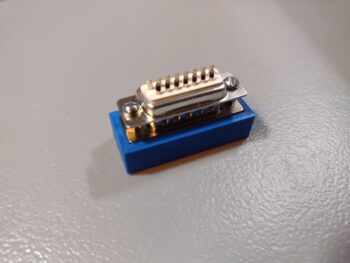
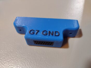
 I stopped off at the “Aviation Department” of my local True Value Hardware store to pick up some 1/2″ long 4-40 screws for my new G7 D-Sub + bracket ground bus… the new screws worked a treat!
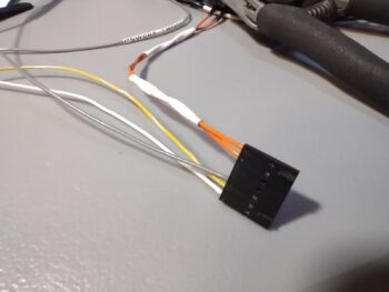
 I then got busy selecting wires (white, gray and yellow) and terminating them with tiny sockets, then inserting the wires into the JB Wilco Canopy & Gear warning system’s J2 connector . . .
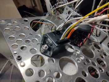
 Yes! Even though the darned thing is this small, it has TWO (2) connectors on it. Of course after digging in the manual I realized the 3-socket power connector was wired backwards (yes, even I do dumb things!)… so I swapped the two end wires, since thankfully the middle wire was correct! I was 33% correct! ha
The two wires left to terminate in the J2 connector will come from the nose gear actuator microswitches [Note the mojamma piezo buzzer behind it, which is part of this warning setup].
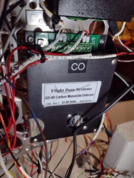
 I then spent the next 45 minutes wiring up the GD-40 CO Detector. Here you can see from left-to-right are the two RX-232 wires that feed the HXr warning/alarm data, the audio wire to the audio mixer, and on the far right end are ground and power. EZ-PZ!
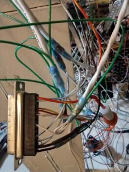
I’ll note that cable-management has not commenced in earnest yet on the Tri-Paragon, thus why the rats’ nest look continues at this point.
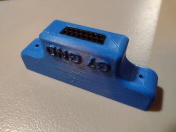
 Shortly after I tested the 1/2″ 4-40 screws, I got into CAD for about 10 minutes and finished the “initial final” design of the G7 Ground Bus mounting bracket. I threw some raised letters on it for some fun bling (pic 1) and also made an angled notch for the exit of the two thicker wires that will tie this ground bus into the main panel G4 Ground Bus (pic 2). I then kicked off the 3D print.
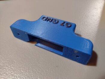
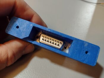
Another shot of the D-Sub face (pic 1), and the inside face of its paired male DB15 connector that will get two 12-14 ga wires soldered to all the solder points (pic 2).
I received my order from Stein Air that included a fair number of connectors, including this mini-Molex connector for the two wires exiting out of the Warning Annunciator Sub-panel for the Indicator Lights’ Push-to-Test (PTT) button circuit. It was a fairly quick kill, so I knocked it off of my to-do list.
Here shown with the both sides of the connector terminated, wires in place. (Yes, I have a love-hate relationship with Mini-Molex connectors… what can I say?!)
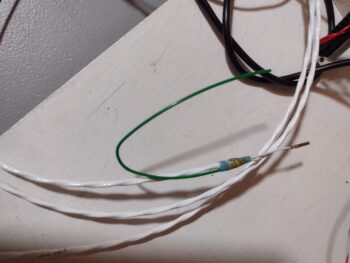
 My last task of the evening was ginning up yet another 22-AWG 2-wire shielded cable with ground pigtail for the Dynon Intercom to Trig TY-91 COM2 radio connection. While there will be a BUNCH of work to finalize the intercom install, this completes the wiring out required before the intercom wiring (attached to the Tri-Paragon) is linked up with what is currently in the aircraft.
 Here’s a shot of that COM2 cable (lower left to upper right of pic) installed into the Dynon Intercom D-Sub connector.
 Notice I didn’t mention any wiring labels: as I’m in an exponential downward curve of needing those (at least for now) as I applied those fairly heavily during my initial forays into the Tri-Paragon… now I’ve had the same single lone label waiting on the “to-be-printed” list for over a day for some new additions (I normally print in batches of 6-7 to maximize the heat shrink material in the cartridges).
Finally, I’ll note that I had some good comms with both Eric Page re. the video cameras’ wiring and Rich on some issues I need to clear up on the AG6s.
Rockin’ and Rollin’!