
Although I got a good bit of stuff knocked out today, I spent a good portion of the morning reacquainting myself with terminating coax cable connectors and installing the pitot/static system. As Abraham Lincoln reportedly said: if he had 7 hours to chop down a tree, he would spend 6 hours sharpening his axe. Thus, my day started out with some mental “axe-sharpening.”
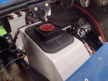
Let’s start off with the low hanging fruit… a question I’ve had for a while was where to put the Dual BlueTooth GPS puck that my iPad requires for GPS when using my FlyQ EFB app. I decided to simply slap it on top of the NG30 cover: making the turning on and off of it a simple opening of the nose hatch and pushing the on/off button, then closing the hatch. EZ-PZ. Task complete.
 In addition, I stopped by the Aviation Parts Store (True Value Hardware) to pick up a 1/4-amp glass fuse for the GIB Bose LEMO jack’s power feed that ties into the Dynon Intercom’s power wire. Both pilot and GIB Bose LEMO jacks tie to the main power wire via inline fuses.
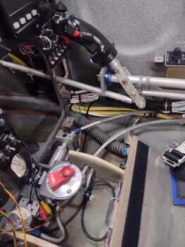
So I installed the fuse and then finalized wrangling all the added Intercom wires, which including swapping out the Adel clamp for a larger size, midpoint between the intercom unit and the pilot headset/headphone jack block (as I did with the Adel clamp between the control stick and panel yesterday). I then secured the bundle of wires as can be seen with the black zip ties.
 Although not very easy to see, I also terminated and routed the ELT antenna cable onto the antenna base (midway vertically between seatbelt clasp and aft armrest mounting tab).
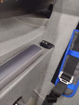
Speaking of seatbelt, clearly it’s visible in the pic above as it is now installed.
The reason for all these final right side pilot seat area tasks is that once I trim the aft upper edge of the armrest and it fits in place, the armrest will be screwed into place with no immediate plan to remove it.
Here’s another shot of the ELT antenna cable routed and secured under the pilot thigh support, where it terminates into the ELT on the left side.
 After a few iterations of notching, trimming, and sanding the aft top edge of the right pilot armrest to fit around the pilot headset/headphone jack block, I then installed and secured the armrest with a couple screws on the aft end… out of the half dozen screws that will get installed later.
 Here’s a closer shot of the pilot’s aft right armrest with the headphone & headset jack block mounted in place.
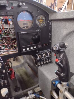
 Back to my “axe-sharpening,” where I found my PowerPoint notes regarding the pitot/static system, with pertinent links to VAF forum posts from Paul Dye’s system that he redid under the guidance and tutelage of Stein. Part of my evaluation was to go ahead and install the TruTrak ADI on the upper right side of the panel . . . and
 part of that install was to assess the placement and real estate required for both the Mini-X and ADI respective GPS pucks, that always come with the requisite bundle of wires that MUST NOT BE TRIMMED to a workable length… the ultimate prank that instrument manufacturers play on us peasants!
 Pitot/static tube line and GPS puck placement assessments aside, the more pressing reason for installing the ADI at this point was to ensure clearance between it and the Trig transponder unit, given that when I designed the panel I FAILED to take into account the length/depth of the Trig transponder’s D-Sub adapter that allows it to be controlled via the HXr EFIS.
My Frankenstein plan is to create a D-Sub pigtail between the adapter and the Trig transponder to provide the clearance required between these two components. I’ll be calling GRT tomorrow to grovel for authorization to engage in such heretical shenanigans.
 And with that folks… pressing forward!