
Today I received my latest order from Mouser, which included my 3K Ohm 3 watt resistor required for the SD-8 Bridge Rectifier ground lead. With my almost last component for the SD-8 on hand (now I need to order a DPDT relay . . . more on that below), I got to work installing it.
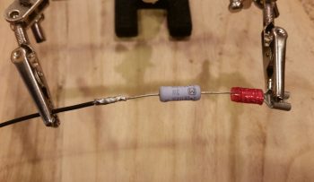
The first task was to simply crimp a red PIDG Fast-ON terminal to the end of the resistor.
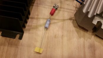
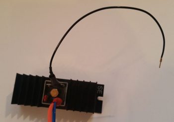
I then soldered my 20 AWG ground wire to the remaining resistor leg.
And then covered all that with some heat shrink. And then terminated the other end with a D-Sub pin to enable connection to the new D-Deck G6 ground bus.
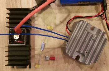
I then connected my latest wiring “feat” to the appropriate tab on the Bridge Rectifier.
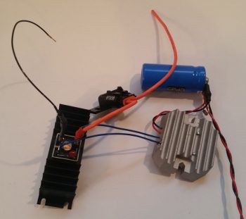
Here’s another shot of the completed SD-8 Bridge Rectifier ground wire (this allows for self excitation of the SD-8 system . . . meaning that it can turn on without having to see voltage from the battery. And not anything else. . . sheesh!).
Over the past few days I’ve been pondering the solution to my IBBS charge lead disconnect during SD-8 only operations, and I finally came to a decision: I will bite the bullet and acquire a DPDT relay to replace the current SD-8’s S704-1 SPDT relay. I then will use the extra position on the new DPDT relay to drive activating current to a small relay in the nose to then disconnect the IBBS charging circuit automatically (as in unseen by me & no additional action required by me). This control relay activation will of course happen any time the SD-8 is turned on.
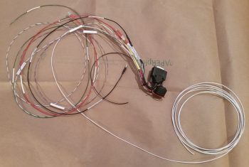
Now, I had ordered some 4-pin SPST relays for another project I’m working on and planned on using one of them possibly for this configuration, but I apparently ordered them in haste and jacked up the actual type: they turned out to be NO relays so I had to find another source. I then dug through my scrap box and ran across the old wiring harness from Jack Wilhelmson’s EZNoseLift nose gear that was on there before I modified the system with Marc Zeitlin’s new AEX system.
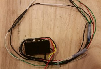
I isolated the best looking relay on the old nose gear wiring harness and then trimmed all the excess wires off the top of it. I then quickly tested out my circuit, and the relay, by hooking up a red LED and 9V battery to the NC side of the relay. Then with the LED in a steady state on, I activated the relay with yet another 9V battery and it opened the switch, thus opening the circuit and turning off the LED. With both my proposed circuit and the relay testing out good, I then proceeded to solder my planned wires to the relay.
I resoldered all new wires to the relay except for one (which was a red power wire… a point of note: I forgot about my service loop to keep the stress off the solder joint so I should have gone with a longer wire and not left the shorter one in place).
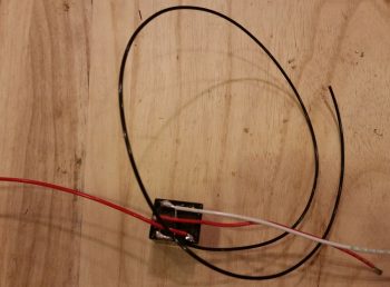
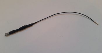
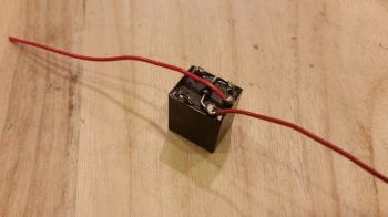
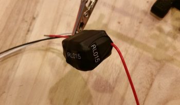
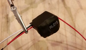
Here’s a shot of the relay with all the wires soldered in place, ready to go…
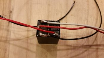 I then wire lace tied the wires to the relay body.
And then added a couple of pieces of larger heat shrink to secure the wires in place to the relay body.
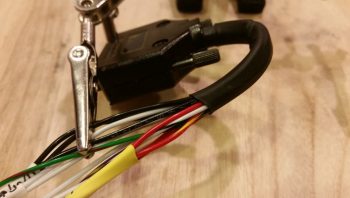
I then grabbed the wiring harness for the IBBS. I found and then isolated the red wire with yellow stripe that is the IBBS recharging wire.
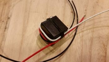
I then cut the IBBS recharging wire lead and soldered in the red power leads from the control relay that I just wired up. After soldering the respective wires to each other, I then hit the pre-added heat shrink with the heat gun to cover the solder splices.
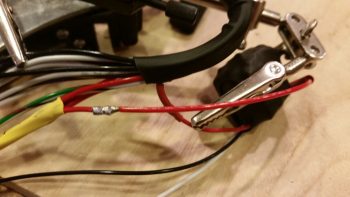
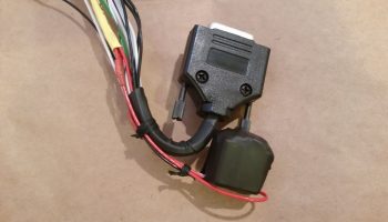
I then wire laced the wires in a couple spots to help secure the new added relay. I did want the relay as close in as I could get it to the IBBS connector, but I would have preferred even a half inch more wiggle room than I got by keeping that original short wire on the relay … but I think all should fit fine once the IBBS is installed.
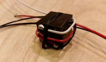
Here’s a closer shot of the new IBBS charging circuit control relay (RL015). You can also better see the wire laced spots in this pic that help to secure the new relay.
One final point of note. Over the past week I have been slowly, bit-by-bit, converting the master Z-13/8 electrical system diagram over to my new isolated starter and B lead circuit architecture, which includes of course having the starter contactor and ANL 40A fuse link up in the nose. Well, after a good hour tonight I was finally able to get my master system architecture updated. With that, I truly hope that I have no major changes left to do on this system!
As a reminder, I’ll be heading to NC tomorrow and will be out of pocket for about a week. Hopefully the weather will get warmer by the time I return so I can actually get some shop work done.