
First off, this blog post covers the past few days… which were a bit busy. Jess and I spent later afternoon into Saturday evening prepping for, and then attending, the EAA holiday party/potluck, which was a good time had by all.
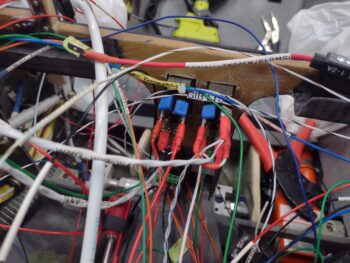
I was able to get most of the landing and wig-wag light switch wired up in the couple hours I had available to work on the plane, finishing it entirely the next day. I then wired up the Nav/Strobe light switch to finish off the switch side wiring for these 2 light switches (the power and ground connections still need terminated into the appropriate busses).
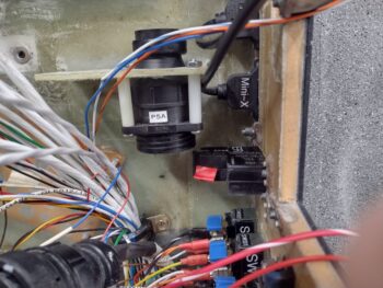
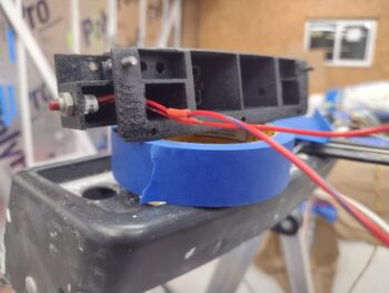
I installed the P5A connector below its bracket (vs on top) with 1″ spacers to assess providing a bit of slack to the control stick cable. It looked fine until I received the battery for the ELT remote switch, and installed both the battery and the switch (temporarily… not screwed) into place.
As you can see, the ELT remote switch intrudes into the space of the P5 connectors —not enough clearance— so I need to go back to the drawing board and consider one of my other options.
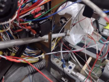
I also hooked up the Landing Brake ground wire (middle of pic – vertical) and the control wire (labeled) that is terminated into the P4 connector (throttle switches’ wire cable). Both these wires tie into a pair of wires that can be seen just above the top outboard corner of the ELT, and together make up one half of the circuit to the Landing Brake switch on the throttle.

I’ve been having an issue with my soldering iron tip giving me grief during splices, etc, so I did a multi-day, multi-hour deep dive on that to order the correct tips and hone my soldering Kung-Fu skills moving forward.
Day 3 I received my order from Steinair, including a new 5A circuit breaker to replace the one that I destroyed with such manly power installing the screw on the wire tab (ha!).
As you can see the new one is in and wired up, with no issues thus far.
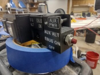
A couple nights ago I copied the wiring circuits from the wiring diagrams and verified the circuits for the Auto Gear Extension system and SD-8 Backup Alternator and E-Bus only switches that both reside in the Warning Annunciator Sub-panel.
In prepping to wire up those switches (thus my critical emphasis on a well-working soldering iron) I drilled/bored out the holes a little on the right side to install the Push-to-Test button for the row of On/Off LED indicators just above the center EFIS. It took a little persuasion, but for the most part the push-button switch cooperated and went into place (pic 1). I then solder-spliced (after cleaning the solder tip with a new compound) wire extensions onto the switch leads to allow the wires to be run through the instrument panel fairly easily (pic 2).
After hauling all the tools into the house for a few rounds of soldering to finalize as much possible on the Warning Annunciator Sub-panel and right (which I’ll work tomorrow), I called it a night.