
I’m not going to lie, looking at the massive amount of wires hanging out of the bird from last night was a bit daunting and overwhelming. I mean, where to start?
Well, luckily I had been building my to-do list so I just started on my post-Triparagon install section of it. That list is a living document and changes day-by-day, and bumped up to the top of the list was both the P4 CPC plug, and more specifically the wiring for the Landing Brake out of the P4 plug.
Starting out late this afternoon (I got a late start), I terminated all but one wire (that goes to the AG6 warning annunciator) from the P4 plug/relays to the landing brake actuator and throttle quadrant micro switch, in that order.
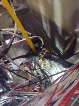
Here we have the 2 white wires to microswitch SW082 on the throttle quadrant which closes a circuit when the throttle is wide open. This in turn closes the landing brake in case it’s open either during a take-off roll or during a go-around.
 I then attached the ground cable from the main battery to the G4 “Forest-of-Tabs” primary avionics bay ground buss (bottom end of yellow pointer)… note the white-labeled wires behind the yellow pointer are the G5 ground buss connector wires, while the wires immediately to the left of the G4 stud are the G7 ground buss connector wires. Note that the upper right half of the pic is the aft side of the F22 bulkhead.
 Here’s that ground cable on the battery end inside the nose battery compartment, awaiting to be terminated with a ring connector.
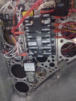
 I then reinstalled the TCW Safety-Trim box onto the Tri-Paragon lower right side, just aft of the center F22 bulkhead and below the G4 Ground Buss discussed above.
 The top aft screw that secures the Safety-Trim box above is also the forward securing screw for the TCW SmartStart unit that I re-secured on the left side as well. I then installed the D-Sub connectors for both the SmartUnit and the Safety-Trim box (which you can just make out through the circular opening above / left of the Smart-Start unit).
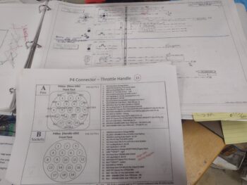
 After nearly an hour of wrangling and organizing the wiring inside the avionics bay, I started to work on the remaining wires that feed into the P4 connector. After hunting down a few wires, I realized something wasn’t right in Denmark… the component wires were just NOT matching what I had on my P4 connector pinout sheet.
I had used the pinout sheet to inventory the P4 connector just a couple of days ago, but now realized it was out of date as compared to the actual wiring diagram. A perfect example of what happens when the paperwork is not updated!
So I took almost another hour (with coffee!) to compare the wiring diagram vs the pinout sheet, confirm the existing wiring inside the bird, and then update my P4 pinout sheet.
 By this point it was getting later into the evening and I was ready to have dinner with my wife, so I called the workday done.
There are still a ton of wires to sort through and connect up, and I expect this to take at least another day or three, but I can already see good progress.
With that, I’ll add: Get ‘er done!