
This is another 2-day blog post.
Starting off, I removed the HXr from the panel to give me better clearance to install the GNS-480 mounting tube into place (without screws) to then ensure there was enough clearance for the attached SkyRadar ADS-B IN receiver… and there was.
 I then checked spacing for the 2 ADS-B IN antennas, and just after confirming they would fit under the right armrest storage bin, I removed the storage bin to allow for mounting the antennas and ground plane. I also confirmed cable lengths of 48″ and 54″, respectively, for the 2 antenna cables. I’ll order those Monday.
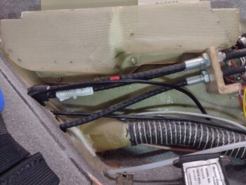 In the nose I removed the tool box, battery, pitot tube and IBBS unit. After removing the IBBS unit I hooked it up to the removed battery, via a separate wiring harness, to charge it.
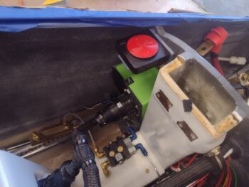
With the nose stuff cleared out, I then set, drilled, countersunk and mounted the Dual GPS antenna puck mounting sleeve on the aft left side of Napster bulkhead, as high up as I could place it.
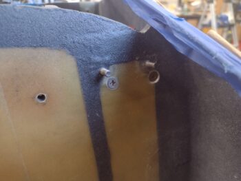
Here we have the front side of the Napster bulkhead with the front of the Dual GPS antenna puck bracket CS screw heads showing (pic 1). These counter sinks, especially the outboard one, were a bit tricky given the internal curvature of the nose. They were also a bit closer to the IBBS upper Clickbonds than I had expected, but again, I wanted the Dual GPS puck as high up as I could mount it.
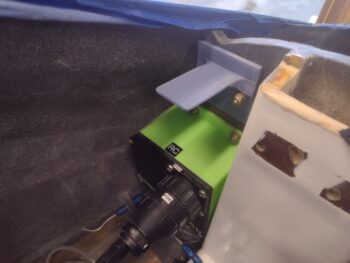
And here is a shot of the Dual GPS puck mounting bracket without the GPS puck in place (pic 2).
Here we have the Dual GPS puck mounted in place and ready for action!
 And a shot of the lower side of the Dual GPS puck mount to show the bottom side of the mount. I knocked the mount just a hair off level as I was drilling the second hole, but this dog will certainly hunt!
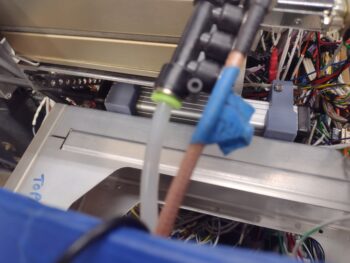
 As my timeline went, I was actually working on the nose taxi light’s internal open/close pivot arm that I designed in CAD and fired off the first 3D print last night for configuration testing today.
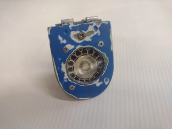
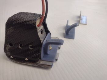
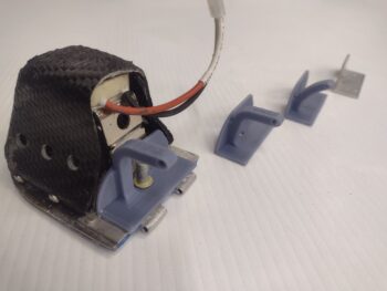
Here’s the front face of the sanded (and soon to be repainted) drop-down taxi light assembly.
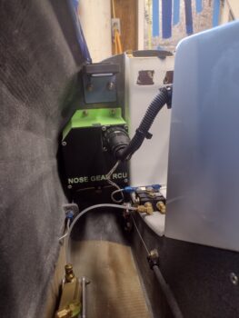
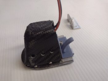
 And the same light assembly, turned face down, with the initial iteration of the open/close pivot arm (pic 1), and then version #2 of the pivot arm after I temporarily installed it in the nose (pic 2)… after each redesign and during each subsequent 3D printing is when I worked on installing the GPS puck mount above [out of curiosity I weighed this part, which came in at 1/3 lb = 5 oz].
Not surprisingly, pivot arm #3 is the most promising yet, and is one that I can actually live test with the taxi light deployment/retraction actuator. Thus, in prep for the taxi light unit open/close test tomorrow, I finished wiring up the taxi light relay (#11) for the test (no pic).
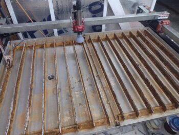
 Yesterday I spent about 45 minutes starting on the initial cleaning of my plasma cutting table water tray. Tonight I spent nearly 2 hours finishing that task (a complete cleaning will involve actually removing all the slats) to allow me to add water —without it turning instantly dirty brown— to get the GPS puck mounting plate and ADS-B IN antenna ground plane/mounting tabs plasma cut.
 I’ll note that I’m working the taxi light final install, along with all the other nose components, so that the next time the battery, etc. is installed the nose compartment will all be squared away to allow me install the nose hatch door…. inching closer!