With pieces parts on order for the canopy latch handle, I figured I would knock out some canopy latch+ related ancillary tasks. To really get the canopy latch completed I will need both the 3D printer and the milling machine online and operational, in that order.
Of course I worked on the milling machine install first because it involved using my hammer drill to make holes in the shop floor for the mill base’s securing bolts. My neighbors aren’t that close, but that thing is still loud!
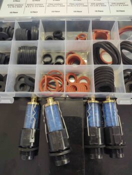
First up however was a trip downtown to Harbor Freight to pick up some ring gasket/seals (or flat O-rings) for the engine desiccant plugs. These desiccant plugs are great for soaking up the moisture in the cylinders, but their design –especially for their price– leaves a little to be desired. To keep the moisture out of the cylinder, as denoted by how long the desiccant stays blue, you need a fairly tight seal on the rubber ring gasket. The problem is a decently firm torque deforms these rubber seals out of shape in too short of time [torque too much and you’ll bust one of these off in your spark plug hole… don’t ask me how I know!].
With new seals in hand I went back home and flipped the engine back upright. I put the refreshed desiccant plugs back in the upper spark plug holes and hooked up the desiccant air dryer to the engine. Task #1 complete.
I then got to work on the mill base, first cutting the strips of very thick hard rubber that I’ll employ for vibration dampening for the mill.
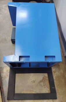
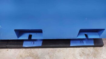
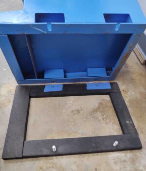
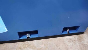
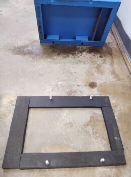
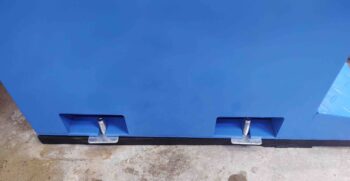
Here’s how the rubber base for the mill base looked on each side. I added blue tape below each bolt attach point to mark the hole drill spots.
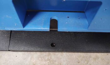
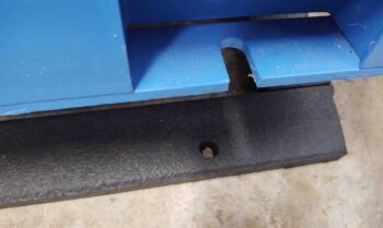
As you can see here.
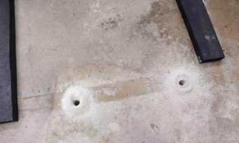
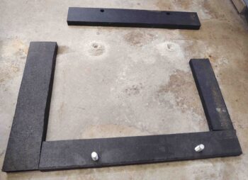
Here are the 2 holes drilled out on the right side.
I then drilled nearly 3″ down into the concrete to create the holes for the threaded mounting studs.
Which I then pounded into place.
A shot of them, one with nut & washer and the other bare.
I then (remarked) and drilled the other side.
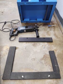
I included a shot of my old, gritty and raw hammer drill. That thing will eat through anything! As you can see I mounted the left side studs and the rubber base padding.
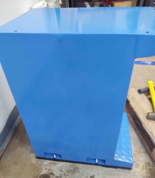
With the mill base in place, I then needed to level it.
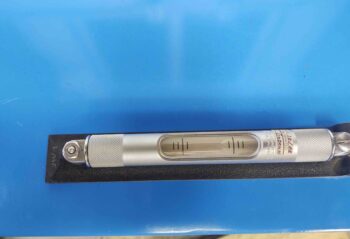
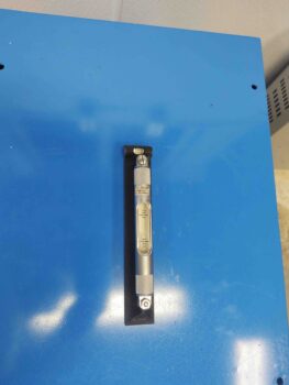
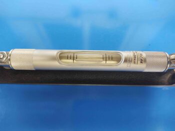
The first pic is the right-to-left level, way off. I then put one metal coupon (leaning against level) on each left side mounting stud to get this result.
Metal coupons added to left side.
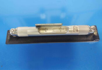
The front-to-back initial level was awful as well (my shop floor is really uneven!).
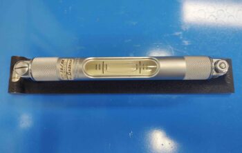
I went to grab some dinner, and these were the results I had for left-to-right and front-to-back levels before I took off. Not bad, but I have two corners floating in midair that need a decent number of shims themselves… which I don’t have on hand. I’ll buy some more tomorrow and continue on.
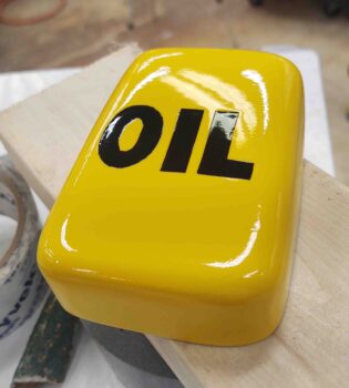
So, I told a bit of a fib just earlier. I actually started off after the engine flip by quickly sanding the nose oil box that’s been sitting on my shop desktop for a good month now. I then hit it with 3 coats of clear total, at differently intervals as I was cutting the rubber strips to mount under the mill base.
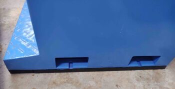
Here’s the clear coated nose oil box lid. The box is no beauty queen, but it’s bright and eye-catching and will do the job.
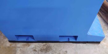
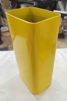
Here’s the actual box here. Also with 3 coats of clear. The coats aren’t as thick on the vertical base just because I didn’t want to risk runs. I’ll wet sand this and buff it out a bit.
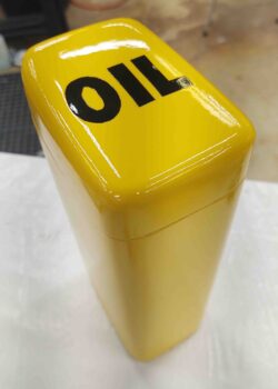
Here it is all together. This oil box will hold a 1-quart bottle of oil nice and tightly with a little room at the top for a couple paper funnels and a rag or two. I plan on mounting it about midway between the Napster bulkhead and the right rudder pedal.
After I returned from dinner I got to work on my plasma cutter.
Last night on my first few cuts after a long time off using the plasma cutting table, the gremlins of it stopping mid-cut and losing plasma arc that I had fixed just after shortly getting it up and running had apparently returned. And believe me, I was not happy. The first run went fine, but the second and third tries had the job stopping at about mid-point.
Now, I did upgrade the firmware, so that might have been the cause… although of course it shouldn’t have been. Frustrated, I hit the forum last night and realized they had finally provided a factory fix for this issue that has afflicted a significant number of new Crossfire Pro plasma cutting table owners.
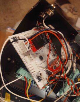
The fix required removing the main control circuit board.
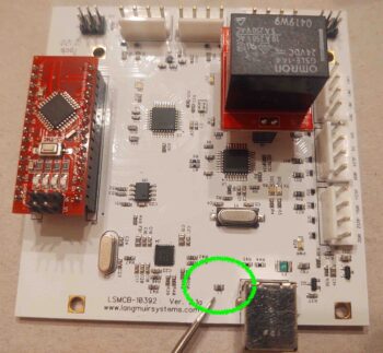
And then locating the tiny L1 Inductor. Ironically, this little guy was supposed to mitigate the noise but apparently turned into quite the antenna, sucking all the noise in and wreaking havoc on the system (again, causing the plasma cutter to stop midway through a job).
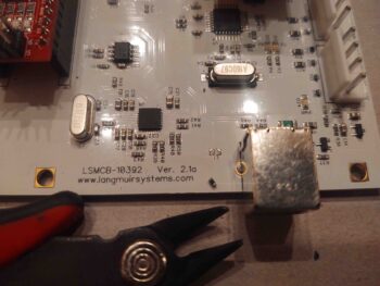
Then removing the offending L1 inductor off the PCB.
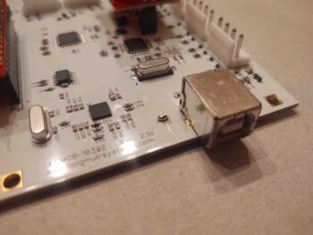
And creating a solder bridge by soldering the remaining nubs together with a very precise blob of solder! (FYI – For the the owners that aren’t comfortable doing this they can send their board into Langmuir Systems and they’ll do it free of charge… also, the units currently shipping have been modified and have L1 removed).
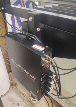
I then reassembled the control box, took it back out to the shop and remounted it.
I’ll test it tomorrow by cutting another test LC-1 Canopy Safety Catch out of mild steel… before then cutting it from stainless steel stock.
And with that, I called it a night.
Now, I will be working on this ancillary stuff until I get my required bits for the canopy latch. It’s a good time to get the 3D printer back online, the plasma cutting table tweaked and the mill on its way to operational status.

