
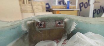
I started off today laying up a ply of BID on each side of the nose hatch hinge bracket mount in the hinge channels. I sanded the channels down first, then dug out some of the blue foam on the sides to then add micro and flox for essentially a flox corner. The ply of BID basically covered the channel outboard walls, the front (bulkhead) part of the channel, the top (nose underside), and then overlapped onto the inboard side of the channel (the protruding hinge bracket mount).
I then did a number of shop tasks not really worth mentioning, before I was then able to work on the instrument panel. I also did a myriad of measuring, fitting and planning for installing the nose hatch door latch and latch hook.
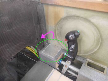
In contrast, a very worthy point of note on the instrument panel is my command decision to move the planned location of the Master switch, Ignition #1 (ElectroAir) and Ignition #2 (P-Mag) from a plate that would have been just forward of the control stick, onto the lower right corner of the panel. After thinking about it for a few days, I just decided that a switch plate forward of the control stick on the side console would just be too much hassle. The more I thought about it the more I liked the idea of having these switches on the panel: they seem to flow better and the fit is more natural.
A number of hours later, after working on a bunch of other panel tasks, I finally got around to marking up the panel in ‘ol skool fashion for the Master and ignition switches.
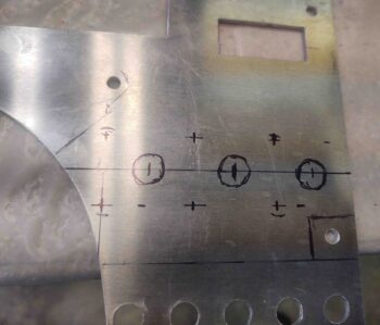
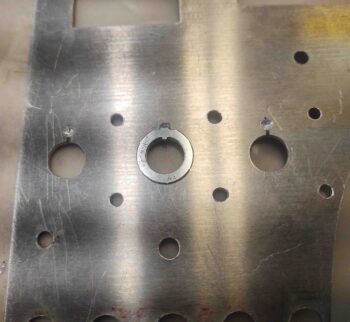
After drilling the master and ignition switch holes, I then used my 3D printed large switch template for drilling keyways on the back side of the panel. I actually drilled the keyways for every large switch on my panel (6 total).
Here I’ve marked the keyway location . . .
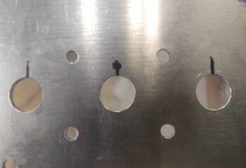
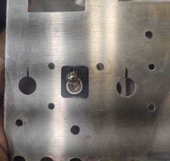
And then carefully drilled it out. You want to get deep enough (around ~1/16″) so that the keyway will sit flat on the panel with the key in the hole, but obviously NOT drill all the way through the panel and have a nice hole where you don’t need one.
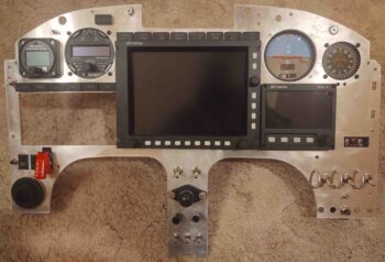
I then reassembled the panel…. this is post welding, so there are a number of areas that I tweaked and repaired by welding the holes in (as in the upper right CAMLOC) or just making them smaller.
Note the 2 holes below the vertical card compass that provide access to the adjustment screws. Also note the 2 dimmer switches on the center strut are installed.
About the only tasks left to do on the panel, besides actually installing it, are fitting the Garmin GNS-480 GPS and drilling the keyways for the small switches.
Pressing on!