
Today involved hopefully making the last dusty mess I will make inside the aircraft that I will ever make from here on out!
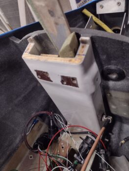
It involved 3 dust-producing tasks, with the first one being to notch the top aft side of the NG-30 upright channel to allow the future StarLink antenna (for inflight realtime Internet/WiFi capability… tested by my R&D guy, Marco! haha) to fit about an inch forward in the nose and better mount onto the top of the NG-30. I taped off and marked the aft side of the NG-30 upright with a slight angle down going aft, to match the bottom of the antenna. And then about an inch forward from the aft wall for the antenna “shelf.”
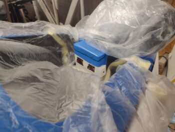
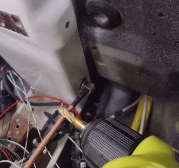
As you can see, I put plastic all around to help mitigate the copious amounts of dust that would be produced from this cut, which I made next.
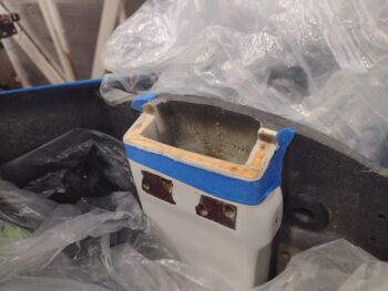
My estimation of how far forward the antenna would nestle into the nose at the outboard corners was off a bit, as the antenna didn’t drop the extra 0.3″ I had planned on… I could have made another cut, but I called this good and will deal with the minor notches forward of the antenna later. This definitely created a good fit for the antenna and I’m calling the op a success.
Dust-creating task #2 was “drilling” a 9/16″ (approx.) hole into the lower right side of the NG-30 upright for the L2 transponder antenna cable connector access.
As with so many jobs on this bird, this task was made quite challenging since I had so little clearance to get a drill/bit into that space to create the hole. I started with quite a small drill bit on the right angle drill just to get the center position of the hole dialed in, but then needed something robust enough to make the hole. Unfortunately any drill bits of decent diameters were simply too long to get anywhere near a straight drilling angle.
My answer? End mills. Yep, short and robust. And since the fiberglass over foam is soft enough to do a plunge cut with an end mill, I just started with a 1/4″ diameter and moved up to a 3/8″ to mill out the material so that this side hole was the proper diameter.
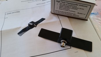
Next up was installing the nearly decade-old bought L-2 transponder antenna (a Christmas gift actually). Note the installation instructions that I poured through to assess if there would be any issues between this antenna and the StarLink Internet/WiFi antenna. The optimized mounting position for the L-2 is vertical, which places the transmission pattern beaming out in all directions horizontally. Mounted vertically, anything above or below the antenna has virtually no effect on its operation.
Obviously I’m not sure how the StarLink antenna will react to this L-2 transponder antenna in operation, and that will be discovered during functional testing. But knowing that this L-2 guy won’t be bothered with the StarLink antenna, I pressed forward with my plan.
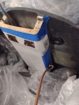
Here’s the L-2 inside the NG-30 upright channel pocket, snugged up to the inside right wall (nose is left side of pic).
Since I needed the L-2 to sit flat against the inside aft wall of the NG-30 upright channel to allow for securing via RTV AND positioned correctly to allow a proper interface with the cable connector, I had to do some checking and minor tweaking of the hole position with my aforementioned “mobile milling machine” (ha!).
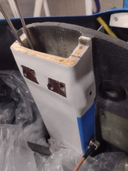
Once the position and angles were all good, I cleaned the mating side of the antennal and inside aft wall of the NG-30 upright channel with acetone before slathering up both sides with the black Toyota RTV goop that I used for my internal carbon fiber baffles on the engine.
I then used foam and wood wedges to press the antenna into place, WHILE it was connected to the antenna cable and snugged up internally to the right sidewall as well… to ensure the cable connector had clearance if I want to remove it while installing all the nose components and wiring them up.
Dust-producing task #3 was simply a 3/8″ hole in the right upper corner of the panel, under the right longeron. This will be for wire transiting from forward to aft of the instrument panel (no pic).
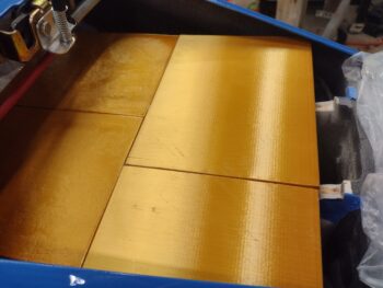
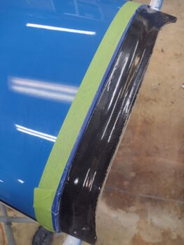
After about an hour of online research my last task of the evening was to sand the quite thick epoxy wipe that I did on the glare shield, a good week or so back (pic 1).
As I believe I mentioned before, as a GLARE shield I want the surface to be dull and non-reflective of sunlight. But I also want the carbon fiber weave to be visible, uniform and look halfway decent.
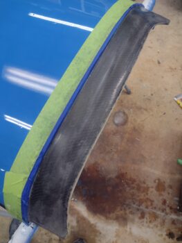
After my research, my conclusion is that I will need to clearcoat (matte) the glare shield to bring out the weave to make it visible, and hide the sanding imperfections. That being said, I wet sanded the epoxy wiped glare shield starting off with a couple rounds of 320 grit to block down the thickness of the epoxy a good bit, and then stepped through successive rounds of 800 → 1500 → 2000 → 2500 → 3000 grit before calling it good (pic 2).
Besides there being virtually no bright shiny spots remaining (all leveled), the surface is, not surprisingly, exceptionally smooth. I’m very happy with how this turned out, and I’m hoping that after 2-3 rounds of clearcoat, the carbon fiber weave will be visible and surface looking uniform.
Now that I’ve got some of these mess-producing tasks knocked out, and the bird’s insides cleaned up again, I can press onward in getting electrical components installed and wired up.